 Open Access Article
Creative Commons Attribution 3.0 Unported Licence
In situ nano-sized ZrC/ZrSi composite powder fabricated by a one-pot electrochemical process in molten salts
Hongxia Liu ab,
Yanqing Caic,
Qian Xu*d,
Huijun Liue,
Qiushi Songa and
Yang Qia
aSchool of Materials Science and Metallurgy, Northeastern University, Shenyang 110819, PR China
bSchool of Materials Science and Engineering, Inner Mongolia University of Technology, Hohhot 010051, PR China
cCollege of Material Science and Engineering, North China University of Science and Technology, Tangshan 063009, China
dState Key Laboratory of Advanced Special Steel, Shanghai University, Shanghai 200072, PR China. E-mail: qianxu@shu.edu.cn
eLaboratory for Corrosion and Protection, Institute of Metal Research, Chinese Academy of Science, Shenyang 110016, PR China
First published on 12th January 2017
Abstract
ZrC/ZrSi nanocomposite powders are in situ synthesized from ZrSiO4 and carbon through a one-pot electrochemical process. The pathway from the precursor of ZrSiO4/carbon to ZrC/ZrSi composites is investigated by time-dependent electrochemical reduction experiments. The results show that the composite powder involving nano-sized ZrC particles dispersed inside the ZrSi matrix is fabricated through an electrochemical route. The ratio of ceramic phases to metallic phases in the final products can be controlled by adjusting the amount of carbon in the original materials. The electrochemical route in molten salt provides a feasible method for in situ preparation of nano-sized ZrC/ZrSi composite powders at relatively lower temperature.
Introduction
Zirconium carbide (ZrC) is an Ultra-High Temperature Ceramic (UHTC). It has a very high melting point, hardness, and Young modulus because of the strong covalent Zr–C bond. ZrC also has high thermal conductivity and electrical conductivity, both of which are similar to that of zirconium metal.1,2 In particular, ZrC has a lower density (6.73 g cm−3) compared to some other carbides. Therefore, ceramics and composites based on ZrC have been attracting a lot of attention as ultra-high temperature structural materials for potential applications in re-entry vehicles, rocket jet engines or supersonic vehicles under extreme-environments.3,4 In addition, ZrC is a good candidate as an inert matrix material and refractory fuel coating material for high-temperature gas-cooled reactors (HTGR) due to its low neutron absorption cross-section and weak damage sensitivity under irradiation.5,6 However, the poor solid-state sinterability and oxidation resistance of ZrC make it very challenging to be widely applied. One way to overcome these obstacles is to make composites, adding for example silicides, refractory metal or their alloys.3,7–9 Among these, ZrSi, as an intermetallic compound, possesses many desirable properties, such as good oxidation resistance at high temperature, excellent acid resistance including aqua regia, high thermal shock resistance, high thermal and electrical conductivity. However, the expensive pure Zr and Si are typically used as raw materials in most of the methods for preparing ZrSi.10,11 Besides, in order to simultaneously improve the strength and ductility of the carbide–metal composites, the sizes of the carbide particles should be decreased from micrometer to nanometer.12–14Actually, several methods have been used to prepare ultrafine or nano-sized cermets,14–16 and the methods can be divided into ex situ and in situ processing routes. The ex situ processing approach is a conventional method, in which the nano-sized carbide particles are synthesized separately and then incorporated into the metallic matrix. There are some disadvantages for the ex situ method, such as low bonding strength or wettability between carbide particles and the metallic matrix due to the interfacial contamination. On the other side, the carbide particles can form in the metallic matrix by the in situ processing approach and the clear reinforcement–matrix interfaces which are free from contamination can be formed. Self-propagating high-temperature synthesis (SHS), known as combustion synthesis (CS), is a normal in situ method to fabricate carbide particle–reinforced metal matrix composites. Although this method exhibits some advantages, such as high purity of products, low energy requirements and relative simplicity of the process, the exothermic heat generated during SHS reactions can increase the temperature of the adiabatic system up to ∼1800 K, under which the carbide particles become much coarsening. Therefore, it is highly desired to develop an alternative method to produce ultra-fine powders of zirconium-based composites at moderate temperature. Fortunately, it is reported that the alloys, metal carbides or metal–carbide composites can be successfully obtained by electro-deoxidation of the mixed metal oxides or metal oxides/carbon precursors in molten salt, such as TiZr,17 TbNi5,18 TiMo,19 Nb3Sn,20 Ti5Si3,21 HfC,22 TiC23 and Fe–TiC24 composites. Usually, the electrochemical synthesis in molten salt can be carried out at 800–900 °C, much lower than that of SHS. Therefore, nanosized ZrC/ZrSi composites may be in situ produced by direct electrochemical reduction of zirconium silicate (ZrSiO4) and carbon (C).
In this work, in situ nano-sized ZrC/ZrSi composite powder was fabricated using the raw materials of zircon and carbon powders by a one-pot electrochemical process in the CaCl2–NaCl melt. The possible reaction pathway of the electrochemical process was investigated by examination of the samples after different durations of reactions, in order to reveal the relationship between the micro-structure of ZrC/ZrSi composite powders and the mechanistic of the reactions.
Experimental
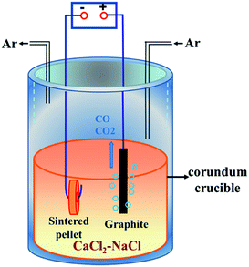
Commercial ZrSiO4 (ZrO2, 66%; Alfa Aesar) and nanoscale carbon black (analytically pure; Tianjin No. 3 Chemical Reagent Factory) powders were used as raw materials. ZrSiO4 and carbon powders were firstly ball-milled with anhydrous alcohol for 4 h. The contents of carbon black in the raw material were set to 3%, 6% and 14% in mass. Then, the ZrSiO4/C mixed powders were uniaxially pressed into cylindrical pellets (Ø 15 × 1 mm, 0.6 g) under a pressure of 8 MPa, which were finally sintered at 950 °C for 4 h in a flowing high-purity argon atmosphere (Shenyang ruike gas company). The sintered ZrSiO4/C pellet, which was connected to a Ni wire (2 mm in diameter) through the hole drilled in its center, was served as a cathode. A high-density graphite rod (Ø 10 × 60 mm) connected to a 304 stainless steel wire was used as an anode. The CaCl2–NaCl eutectic mixture (analytically pure, Tianjin Kemiou Chemical Reagent Co., Ltd.), served as the electrolyte, was firstly dried at 300 °C in air for 24 h and then put into a stainless steel reactor heated at 300 °C for 24 h in Ar atmosphere. More details of the electrolytic cell are schematically shown in Fig. 1. Prior to the electrolysis, the CaCl2–NaCl melt was pre-electrolyzed at 2.5 V for 2 h in order to remove electrochemically active impurities in the melt. For the pre-electrolysis, the graphite rod (Ø 10 × 60 mm) electrodes were used for both anode and cathode. The electrochemical reduction of ZrSiO4/C mixtures was performed under a constant voltage of 3.1 V at 850 °C. The voltage was supplied by a DC stabilized power supply (WYJ-40 A-15 V, Hangzhou apple instrument co., LTD). The incompletely and completely reduced samples were obtained by terminating the electrochemical reduction after different reaction times ranging from 10 min to 20 h.After electrolysis, the pellet was lifted out of the melt and positioned at the top of the reactor to be cool down under the continuous flow of Ar. Then, the sample was rinsed with tap water carefully to remove the adhering salts from the pellet and immersed in distilled water for 24 h, in ethanol for 12 h and finally dried in air at room temperature.
The phase composition of samples was identified by X-ray diffraction (XRD, ultima IV, Rigaku, Japan). The microstructure of the sample was characterized by scanning electron microscope equipped with an energy-dispersive X-ray spectroscopy (SEM and EDS, EVO18, Carl Zeiss, Germany) and transmission electron microscope (TEM, JEM-2100F, Japan).
Results and discussion
Synthesis of ZrSi/ZrC composites
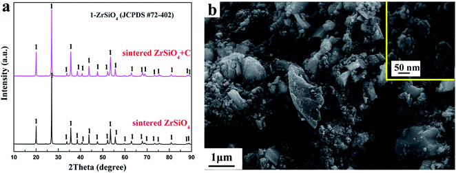
The XRD patterns of the ZrSiO4 and ZrSiO4/C mixed pellets sintered at 950 °C for 4 h are shown in Fig. 2a. It can be seen that the XRD patterns of sintered ZrSiO4/C mixtures and ZrSiO4 are almost the same. However, the weight loss of ZrSiO4/C mixed pellets is less than 1 wt% after the sintering. The typical peaks of carbon were not detected probably due to the amorphous structure of carbon black used in this study. Furthermore, the existence of a single phase of ZrSiO4 in Fig. 2a suggests few reactions between ZrSiO4 and carbon during the sintering. Therefore, the carbon black would not be used as the reducing agent but as the carbon source for the carbide formation during the electro-reduction process in molten salts at 850 °C.Fig. 2b shows the morphology of the ZrSiO4/C (3 wt% C) pellet after sintering at 950 °C for 4 h. Two types of particles can be distinguished. The bigger particles are ZrSiO4, whereas relatively fine particles among the ZrSiO4 particles should be carbon black. The carbon black is composed of particles with an average size less than 50 nm (see the insert).
Constant voltage electrolysis is applied to reduce the sintered pellet of ZrSiO4/C mixtures under 3.1 V at 850 °C in molten CaCl2–NaCl. After electrolysis for 20 h, the final product is composed of the ceramic phase ZrC and the metallic phase ZrSi, as shown in Fig. 3a. With increasing the amount of carbon added, SiC can be detected in addition to ZrC as ceramic phases, as shown in Fig. 3b and c. These indicate that upon the cathodic polarization of ZrSiO4 with the presence of carbon in molten CaCl2–NaCl, oxygen atoms in the cathode can be removed into the molten salt, meanwhile the atoms of Zr, Si and C remain in the cathode. Among them, C is more preferential to combine with Zr and form ZrC, while Si alloys with Zr, which is in good agreement with the Gibbs energy changes calculated for the corresponding reactions shown in eqn (1)–(3). Moreover, when more carbon is added, the amount of the carbide phase increases and correspondingly the amount of the metallic phase decreases. It suggests that carbon is predominantly used as the carbon source for the carbonization rather than the reducing agent for the oxygen removal. Hence, it can be conclude that the ratio of carbide phases to metallic phases in the final product can be controlled by adjusting the amount of carbon added to the ZrSiO4/C mixed precursor.
| C(s) + Zr(s) = ZrC(s), ΔGθT=1123 K = −211.53 kJ mol−1 | (1) |
| C(s) + Si(s) = SiC(s), ΔGθT=1123 K = −88.44 kJ mol−1 | (2) |
| Si(s) + Zr(s) = ZrSi(s), ΔGθT=1123 K = −152.92 kJ mol−1 | (3) |
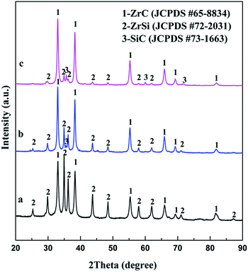 | ||
| Fig. 3 XRD patterns of products from electrolysis of ZrSiO4/C pellets with (a) 3 wt% C; (b) 6 wt% C; (c) 14 wt% C under 3.1 V at 850 °C for 20 h. | ||
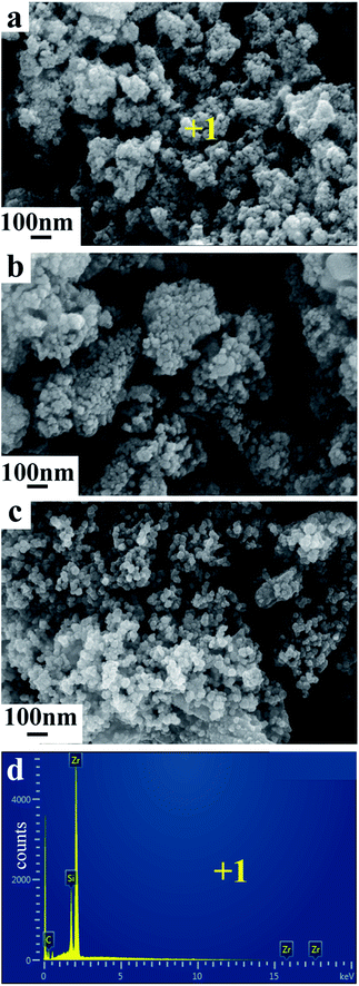
Fig. 4 show the SEM images and EDX analysis of products obtained from ZrSiO4/C mixed pellets with different carbon content. The mean diameter of the primary composite particles is around 50 nm, and these nano-sized particles are prone to form the bigger aggregates, as shown in Fig. 4a. In addition, with increasing the amount of carbon added, the composite nanoparticles are becoming less aggregative to one another, as shown in Fig. 4b and c. It should be due to the fact that the amount of metallic phase ZrSi, served as binder, decreases when the amount of carbon added increases according to the typical XRD patterns shown in Fig. 3a–c. Furthermore, the EDX analysis of point 1 labeled in Fig. 4a indicates that the composite nanoparticles consist of Zr, Si, and C, which further confirms the final product is composed of ZrC and ZrSi. This is in agreement with the XRD result.
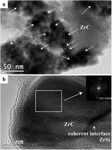
Fig. 5 shows TEM images of the product from electrolysis of pellets with 3 wt% C under 3.1 V at 850 °C for 20 h. As shown in Fig. 5a, the ZrC particles with size of 10–40 nm are dispersed within the ZrSi matrix to form a composite powder with the multicore–shell structure. The interface between the ZrC nanoparticles and the ZrSi matrix is coherent and compatible, as shown in Fig. 5b. All the ZrC nanoparticles are covered by the metallic ZrSi phase which can protect the carbide particles from oxidation and enable the densification of ZrC at lower temperatures.
The reaction pathway
To identify the mechanism of the formation of ZrC/ZrSi composites, a series of electrolysis experiments of ZrSiO4/C (3 wt% carbon) mixed pellets were carried out with different durations ranging from 10 min to 20 h.Fig. 6a displays the XRD pattern of the sample electrolyzed at 3.1 V for 1 h. The result shows that the sample is composed of residual ZrSiO4, ZrSi, CaxZr1−xO2−x (0.1 < x < 0.2, CSZ) and CaSiO3, whereas no peaks are ascribed to any carbide. The existence of CSZ and CaSiO3 indicates that ZrSiO4 is decomposed by CaO, i.e. ZrO2 and SiO2 are separated from the ZrSiO4 molecular, and combined with CaO. Silica is more affiliative to capture CaO and form CaSiO3, and this result is quite similar to that reported by Wang.25 Meanwhile, both of them can be reduced and alloyed to the ZrSi phase. Hence, in the first hour of electrolysis, decomposition reactions and oxygen removal rather than carbiding reaction occurred on the cathode. Although the formation of ZrC is much more preferential thermodynamically compared with ZrSi, the earlier occurrence of ZrSi is probably due to kinetics control. Therefore, the possible reactions occurred at the cathode for the first hour stage are described as eqn (4)–(7).
| (1 − x)ZrSiO4 + Ca2+ + O2− = CaxZr1−xO2−x + (1 − x)CaSiO3 | (4) |
| CaxZr1−xO2−x + 4(1 − x)e = (1 − x)Zr + xCaO + 2(1 − x)O2− | (5) |
| CaSiO3 + 4e = Si + CaO + 2O2− | (6) |
| Zr + Si = ZrSi | (7) |
| CaxZr1−xO2−x + 4(1 − x)e + (1 − x)C = (1 − x)ZrC + xCaO + 2(1 − x)O2− | (8) |
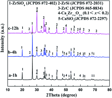 | ||
| Fig. 6 XRD patterns of the ZrSiO4/C (3 wt% carbon) mixed pellets electrolyzed under 3.1 V at 850 °C in CaCl2–NaCl melt for (a) 1 h; (b) 4 h; (c) 12 h. | ||
After the 4 h reduction, as shown in Fig. 6b and c, a new phase ZrC appears, implying that carbiding has occurred on the cathode. The electro-deoxidation and carbonization should occur synergetically on the cathode in the latter stage, and the corresponding reaction is shown in eqn (8). In addition, with the increasing of the duration, the intensities of the peaks ascribed to ZrSiO4 decrease significantly, with the rise of the peaks related to CSZ, CaSiO3, ZrSi and ZrC simultaneously. Finally, with the further electrochemical reduction and carbiding of the cathode, that is after 20 h, the ZrSiO4/C mixture changes to ZrC/ZrSi composite completely, as shown in Fig. 3a.
Fig. 7 shows the photographs of the washed pellets after electrolysis at 3.1 V during the first hour of the process. Obviously, the color of the area near to the Ni lead wire changes to black after electrolysis for 10 min. Then, the black color expands radially from the Ni lead wire during the electrolysis proceeding, indicating the area where the reactions occur. It can be deduced that the decomposition of ZrSiO4 with CaO in the melt should occur synergetically with the electro-deoxidation of the oxides. The oxygen ion in CaO mainly comes from the oxide compound on the cathode, in which the oxygen atoms are ionized and removed to the melt during the electro-deoxidation.
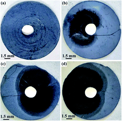 | ||
| Fig. 7 Photographs of the contacting electrodes of ZrSiO4/C (3 wt% C) mixtures after electrolysis under 3.1 V at 850 °C in CaCl2–NaCl melt for (a) 0 min; (b) 10 min; (c) 30 min; (d) 60 min. | ||
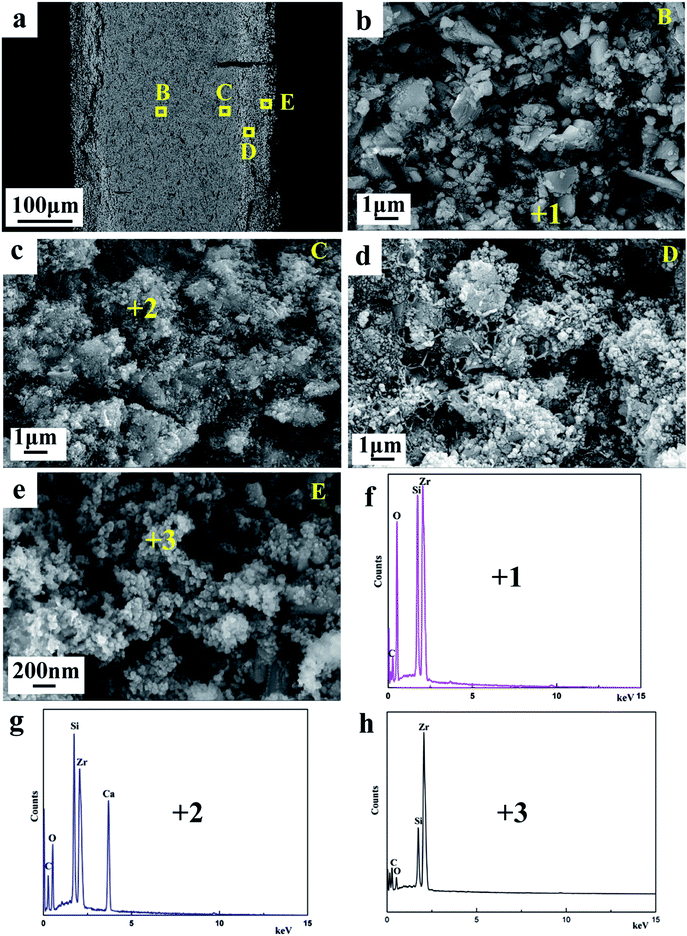
Fig. 8a displays the SEM image of the cross-section of the partially reduced sample for 4 h, which reveals the layered structure. Fig. 8b–e show the evolution of cathodic particles during the cathodic polarization. The morphology at the inner layer B of the sample shown in Fig. 8b is similar to that of the sintered ZrSiO4/C precursor (Fig. 2b), indicating that the inner portion of the pellet remains almost unreacted. According to the result of EDS (Fig. 8f) combining with the XRD result (Fig. 6b), the composition at the area B should be ZrSiO4 and carbon. The coarse and dense particles emerge at the area C of the sample, as shown in Fig. 8c. They contain some calcium-containing intermediate compounds (CSZ and CaSiO3) since calcium can be found in the EDS analysis in Fig. 8g. The area D should be the midway to the final products, where the loose and fine particles can be observed. As shown in Fig. 8e, at the area near to the surface of the pellet, the final products can be gained and they are composed of ZrSi and ZrC according to the analyses of EDS (Fig. 8h) and XRD (Fig. 6b), with the morphology of interconnected nodular particles. It can be deduced that the molten salt plays an important role for the formation of ZrSi and ZrC from the precursor of ZrSiO4/C. The permeation of molten salt to the cathode pellet along the depth direction can affect both the electrochemical reduction and decomposition of ZrSiO4 with CaO. The electrochemical reduction can achieve only when the oxygen ions on the cathode remove to the melt, while ZrSiO4 is decomposed with CaO in the molten salt, to form CSZ and CaSiO3 as the intermediate.
The pathway of preparation of ZrC/ZrSi composite from the mixture of ZrSiO4/C is schematically illustrated in Fig. 9. The main pathway begins with the electro-deoxidation of the oxide compound, so the site of the early reaction within the cathode is near to the current lead (Ni wire). The alloy of ZrSi is prepared firstly as one of the products, and serves as the metallic matrix. Then, the carbide particles can form in the metallic matrix by carbiding with carbon black in the cathode. The byway during preparation of ZrC/ZrSi composite is about the decomposition of ZrSiO4. The oxygen ion, which is from the initial melt26,27 or removed electrochemically from the cathode, combines with calcium cations and form CaO in the melt. The CaO can decompose ZrSiO4 to form CaSiO3 and CSZ, and come back to the cathode again. Furthermore, both of the oxide compounds can be electro-deoxidated, and release CaO and O2− to the melt. Thus, the byway joins to the main pathway of preparation of ZrC/ZrSi composite.
 | ||
| Fig. 9 Schematic illustration of the electrolytic synthesis of ZrSi/ZrC composites from the solid ZrSiO4/C mixture in molten CaCl2–NaCl. | ||
Conclusions
The nano-sized ZrC/ZrSi composites are successfully prepared by a one-pot electrolytic process from ZrSiO4/C mixed precursors under 3.1 V at 850 °C in eutectic CaCl2–NaCl melt. The composite powder is featured by the ZrSi matrix reinforced with the dispersed ZrC nanoparticles. It is found that the ratio of carbide phases to metallic phases in the final product can be controlled by adjusting the amount of carbon in the initial materials. The reduction pathway of ZrSiO4 and carbon to ZrC/ZrSi composite can be divided into two stages. In the first stage, ZrSi and intermediate compounds (CaSiO3 and CaxZr1−xO2−x) are formed by the electrochemical reduction and the decomposition of ZrSiO4 with CaO. In the second stage, ZrC is formed by the synergetic process of electrochemical reduction and in situ carbiding, and ZrC/ZrSi composite is obtained.Acknowledgements
The authors acknowledge the financial support of the National Natural Science Foundation of China (Grant No. 51174055).References
- M. S. Song, B. Huang, M. X. Zhang and J. G. Li, Powder Technol., 2009, 191, 34–38 CrossRef CAS.
- Y. Yan, Z. Huang, X. Liu and D. Jiang, J. Sol-Gel Sci. Technol., 2007, 44, 81–85 CrossRef CAS.
- L. Silvestroni, D. Sciti, M. Balat-Pichelin and L. Charpentier, Mater. Chem. Phys., 2013, 143, 407–415 CrossRef CAS.
- S. E. Landwehr, G. E. Hilmas, W. G. Fahrenholtz, I. G. Talmy and S. G. DiPietro, Mater. Sci. Eng., A, 2008, 497, 79–86 CrossRef.
- X.-G. Wang, J.-X. Liu, Y.-M. Kan and G.-J. Zhang, J. Eur. Ceram. Soc., 2012, 32, 1795–1802 CrossRef CAS.
- D. Gosset, M. Dollé, D. Simeone, G. Baldinozzi and L. Thomé, J. Nucl. Mater., 2008, 373, 123–129 CrossRef CAS.
- X.-G. Wang, W.-M. Guo, Y.-M. Kan, G.-J. Zhang and P.-L. Wang, J. Eur. Ceram. Soc., 2011, 31, 1103–1111 CrossRef.
- J.-H. Kim, M. Seo and S. Kang, Int. J. Refract. Met. Hard Mater., 2012, 35, 49–54 CrossRef.
- D. Sciti, S. Guicciardi and M. Nygren, Scr. Mater., 2008, 59, 638–641 CrossRef CAS.
- I.-J. Cho, K.-T. Park, S.-K. Lee, H. H. Nersisyan, Y.-S. Kim and J.-H. Lee, Chem. Eng. J., 2010, 165, 728–734 CrossRef CAS.
- A. Tkachenko and T. Y. Kosolapova, Powder Metall. Met. Ceram., 1968, 7, 178–181 CrossRef.
- W. S. Tian, D. S. Zhou, F. Qiu and Q. C. Jiang, Mater. Sci. Eng., A, 2016, 658, 409–414 CrossRef CAS.
- J. B. Ferguson, F. Sheykh-Jaberi, C.-S. Kim, P. K. Rohatgi and K. Cho, Mater. Sci. Eng., A, 2012, 558, 193–204 CrossRef CAS.
- K. B. Nie, X. J. Wang, X. S. Hu, L. Xu, K. Wu and M. Y. Zheng, Mater. Sci. Eng., A, 2011, 528, 5278–5282 CrossRef CAS.
- B. Dikici, M. Gavgali and F. Bedir, J. Compos. Mater., 2011, 45, 895–900 CrossRef CAS.
- A. Matin, F. F. Saniee and H. R. Abedi, Mater. Sci. Eng., A, 2015, 625, 81–88 CrossRef CAS.
- J. Peng, H. Chen, X. Jin, T. Wang, D. Wang and G. Z. Chen, Chem. Mater., 2009, 21, 5187–5195 CrossRef CAS.
- G. Qiu, D. Wang, X. Jin and G. Z. Chen, Electrochim. Acta, 2006, 51, 5785–5793 CrossRef CAS.
- R. Bhagat, M. Jackson, D. Inman and R. Dashwood, J. Electrochem. Soc., 2008, 155, E63–E69 CrossRef CAS.
- B. A. Glowacki, D. J. Fray, X. Y. Yan and G. Chen, Phys. C, 2003, 387, 242–246 CrossRef CAS.
- X. Zou, X. Lu, Z. Zhou, W. Xiao, Q. Zhong, C. Li and W. Ding, J. Mater. Chem. A, 2014, 2, 7421–7430 CAS.
- A. M. Abdelkader and D. J. Fray, J. Eur. Ceram. Soc., 2012, 32, 4481–4487 CrossRef CAS.
- X. Y. Yan, M. I. Pownceby, M. A. Cooksey and M. R. Lanyon, Trans. Inst. Min. Metall., Sect. C, 2009, 118, 23–34 CAS.
- S. Lin, Q. Song, Q. Xu, Z. Ning, X. Lu and D. J. Fray, New J. Chem., 2015, 39, 4391–4397 RSC.
- Z. Wang, Q. Xu, M. Xu, S. Wang and J. You, RSC Adv., 2015, 5, 11658–11666 RSC.
- C. Schwandt and D. J. Fray, Electrochim. Acta, 2005, 51, 66–76 CrossRef CAS.
- Q. Song, Q. Xu, X. Kang, D. Ji-hong and X. Zheng-ping, J. Alloys Compd., 2010, 490, 241–246 CrossRef CAS.
| This journal is © The Royal Society of Chemistry 2017 |

