DOI:
10.1039/C6RA26110H
(Paper)
RSC Adv., 2017,
7, 2943-2952
Facile synthesis of Bi2MoO6–MIL-100(Fe) metal–organic framework composites with enhanced photocatalytic performance
Received
1st November 2016
, Accepted 4th December 2016
First published on 12th January 2017
Abstract
A novel Bi2MoO6–MIL-100(Fe) heterostructure photocatalyst was synthesized by a facile solvothermal method for the first time, and characterized by X-ray diffraction, scanning electron microscopy, X-ray photoelectron spectroscopy, UV-vis diffuse reflectance spectra, transmission electron microscopy, and photoluminescence spectra. The as-prepared Bi2MoO6–MIL-100(Fe) composites exhibited excellent photocatalytic activity and stability towards the degradation of Rhodamine B (RhB) under visible light irradiation. The introduction of MIL-100(Fe) into semiconductor Bi2MoO6 improved the photocatalytic performance remarkably, and the optimal composite with 9% MIL-100(Fe) content showed the highest photocatalytic activity. According to the active radical trapping experiments, the h+ and ˙O2− radicals were the two main active species in the photocatalytic reaction. The enhanced photocatalytic performance is mainly attributed to the formation of the Bi2MoO6–MIL-100(Fe) heterostructure, which is beneficial to the transfer and separation of photo-generated electron–hole pairs. The possible mechanism of the enhanced photocatalytic performance of the Bi2MoO6–MIL-100(Fe) composites was discussed.
1. Introduction
The semiconductor photocatalysis technique has attracted extensive attention in the splitting of water and the degradation of organic pollutants using sunlight as the energy source.1 Among the various photocatalysts, TiO2 is an attractive photocatalyst, because of its low toxicity, high photocatalytic activity and long term chemical stability.2–4 However, the applications of TiO2 are severely limited, owing to it only being excited by ultraviolet (UV) light which accounts for less than 5% of the solar spectrum. Therefore, many reports are focused on developing visible light responsive photocatalytic materials to replace TiO2, such as Bi2MoO6,5 In2O3,6 Ag3PO4,7 and g-C3N4 (ref. 8) photocatalysts.
Bi2MoO6 is a typical Aurivillius oxide, exhibited excellent photocatalytic activity under the visible light irradiation.9 Compared with TiO2, Bi2MoO6 has a lower band gap (2.5–2.8 eV), which makes it utilize more sunlight and displays remarkable photocatalytic performance for organic pollutant degradation under visible light irradiation.10 However, the practical application of the pure phase Bi2MoO6 is limited by its poor quantum yield, which is caused by the rapid recombination of photoinduced charge carriers. To further improve the photocatalytic activity of Bi2MoO6, many feasible methods have been explored, including designing textural properties, doping composites11,12 and combining with other semiconductors,13–15 carbon materials16 or noble metals.17 Nevertheless, there is still plenty of space to explore unfulfilled potentials for fabricating Bi2MoO6-based photocatalysts.
Metal–organic frameworks (MOFs) are an extensive class of crystalline materials formed by the self-assembly between metal ions and organic ligands.18 Recently, they have obtained extensive attention owing to their huge potential applications in sensing,19 gas storage,20 drug delivery,21 optical properties22 and catalysis. These MOFs composites can act as catalysts, using unsaturated metal sites and catalytically active organic likers.23,24 Additionally, MOFs exhibit tunable photo-physical and photo-chemical properties, it can work well as excellent candidates for photocatalysis. For example, Dan-Hardi et al. synthesized a new photoactive crystalline titanium dicarboxylate (MIL-125(Ti)), which exhibits high photonic sensitivity under UV-visible irradiation.25 Hou Wang et al. had reported that In2S3@MIL-125(Ti) can remove the tetracycline by adsorption and photocatalysis. These reports showed that some MOFs can be applied in photocatalysis.26 Compared with traditional semiconductor photocatalysts, the superiority of MOFs is their ultrahigh surface area and narrow micropore distribution which may lead to the formation of monodisperse photoactive species supported on MOFs.27 Recently, several semiconductor@MOF heterostructures like CdS@MIL-100(Fe),28 CdS@UiO-66(NH2),18 ZnO@ZIF-8,29 and GaN@ZIF-8 (ref. 30) have been synthesized and exhibited excellent catalytic performance due to their synergistic effect. However, the photocatalytic performance of Bi2MoO6–MOF composites, to the best of our knowledge, has not been investigated.
Herein, we report a novel Bi2MoO6–MIL-100(Fe) composite that shows excellent photocatalytic activity in degradation organic pollutants. A series of Bi2MoO6–MIL-100(Fe) composites with different weight addition ratios of MIL-100(Fe) have been successfully synthesized via a facile solvothermal method. The photocatalytic performance was evaluated by the degradation of Rhodamine B under visible light irradiation. The combination of MIL-100(Fe) remarkably improved the photostability and the photocatalytic efficiency of the photocatalyst for degradation RhB. Furthermore, the possible mechanism of the enhanced photocatalytic performance of the Bi2MoO6–MIL-100(Fe) composite was discussed.
2. Experimental
2.1 Materials
Bismuth nitrate pentahydrate, sodium molybdate dehydrate were obtained from Tianjin Kemiou Chemical Reagent Co., Ltd. (Tianjin, China), benzene-1,3,5-tricarboxylic acid (H3btc) and Fe powder were purchased from Aladdin Industrial Corporation (Shanghai, China). Ethylene glycol (EG), and ethanol (EtOH) were purchased from Sinopharm Chemical Reagent Co., Ltd. (Shanghai, China). All chemicals were analytic grade and used without further purification.
2.2 Preparation of MIL-100(Fe)
According to the previous literature,31,32 MIL-100(Fe) was prepared by solvothermal method. In detail, a mixture of Fe powder with H3btc, HF, HNO3 and H2O with a molar ratio of 1![[thin space (1/6-em)]](https://www.rsc.org/images/entities/char_2009.gif) :
:![[thin space (1/6-em)]](https://www.rsc.org/images/entities/char_2009.gif) 0.67
0.67![[thin space (1/6-em)]](https://www.rsc.org/images/entities/char_2009.gif) :
:![[thin space (1/6-em)]](https://www.rsc.org/images/entities/char_2009.gif) 2
2![[thin space (1/6-em)]](https://www.rsc.org/images/entities/char_2009.gif) :
:![[thin space (1/6-em)]](https://www.rsc.org/images/entities/char_2009.gif) 0.6
0.6![[thin space (1/6-em)]](https://www.rsc.org/images/entities/char_2009.gif) :
:![[thin space (1/6-em)]](https://www.rsc.org/images/entities/char_2009.gif) 2.77 was synthesized in a Teflon-lined stainless steel autoclave at 150 °C for 24 h. Then the orange solid was centrifuged, washed with ethanol and hot water for several times, and finally dried overnight 60 °C under vacuum.
2.77 was synthesized in a Teflon-lined stainless steel autoclave at 150 °C for 24 h. Then the orange solid was centrifuged, washed with ethanol and hot water for several times, and finally dried overnight 60 °C under vacuum.
2.3 Synthesis of Bi2MoO6–MIL-100(Fe) composite
The as-prepared MIL-100(Fe) with the desired weight addition was dispersed in 10 mL ethanol by ultrasonication to gain the homogeneous MIL-100(Fe)–EtOH dispersion. Next, 2 mmol Bi(NO3)3·5H2O and 1 mmol Na2MoO4·2H2O dissolved in 20 mL ethylene glycol were dropwised into MIL-100(Fe)–EtOH dispersion. After being stirred for 30 min at room temperature, the mixed solution was transferred into a 50 mL Teflon-lined stainless steel autoclave and kept at 160 °C for 12 h. Finally, the obtain samples were collected, washed with deionized water and ethanol, dried overnight at 60 °C under vacuum. According to the method, as-synthesized composites with expected MIL-100(Fe) contents of 3, 6, 9 and 12% were synthesized and named as Bi2MoO6–MIL-100(Fe)-3, Bi2MoO6–MIL-100(Fe)-6, Bi2MoO6–MIL-100(Fe)-9 and Bi2MoO6–MIL-100(Fe)-12, respectively. For comparison, the Bi2MoO6–MIL-100(Fe) physical mixture composites were synthesized by simple mechanical mixture, and named as Bi2MoO6–MIL-100(Fe)-9(M). As a control, pure Bi2MoO6 was also prepared in ethanol under the same reaction conditions as that of Bi2MoO6–MIL-100(Fe) composites except for the addition of MIL-100(Fe).
2.4 Characterization
X-ray diffraction (XRD) patterns of all samples were carried out using an Empyrean diffractometer (PANalytical B.V., Netherlands), with Cu Kα radiation (λ = 1.54184 Å) in the 2θ range of 10–80°. The morphologies and microstructures of the products were characterized by a Merlin field emission scanning electron microscope (FE-SEM, Zeiss). Transmission electron microscopy (TEM) images and high-resolution transmission electron microscopy (HRTEM) images were obtained by FEI Tecnai G2 F20 microscope at an accelerating voltage of 200 kV. The Brunauer–Emmett–Teller (BET) surface area was examined by nitrogen adsorption–desorption isotherm at 77 K on Micromeritics Instrument 3Flex adsorption analyzer. X-ray photoelectron spectroscopy (XPS) was performed on a Thermo Escalb 250Xi spectrometer with a monochromatic Al (Kα) radiation. The UV-vis diffuse reflectance spectra (DRS) of samples were measured with Hitachi U-4100 UV-vis spectrophotometer. The photoluminescence (PL) spectra were tested with an FLS 920 FluorescencLe spectrometer at room temperature.
2.5 Photocatalytic evaluation
The photocatalytic activity of samples was evaluated by the degradation of Rhodamine B (RhB). In experiments, 0.1 g samples were added to 100 mL aqueous solution of RhB (10 mg L−1) in a BL-GHX photochemical reactor (Shanghai Bilon Instrument. ltd. China). A 500 W Xe lamp was used as the visible-light source with 420 nm cut-off filter. Before irradiation, the suspension was kept in the dark under stirring for 30 min to ensure an adsorption–desorption equilibrium. After a given irradiation, about 4 mL suspension was collected, centrifuged and analyzed immediately. The RhB concentration were analyzed by a UV-vis spectrometer (Agilent 8453, USA) at 554. The TOC concentration was analyzed by Shimadzu TOC-LCPN analyzer. The degradation efficiency (%) was calculated as follows:| |
 | (1) |
where C0 is the initial concentration of RhB, and C is the time-dependent concentration of RhB upon irradiation.
3. Results and discussion
3.1 XRD analyses
The crystal structures of the as-synthesized samples were examined by XRD patterns. Fig. 1 shows the XRD patterns of Bi2MoO6, and Bi2MoO6–MIL-100(Fe) composites with different contents of MIL-100(Fe). For comparison, the patterns of pure MIL-100(Fe), Bi2MoO6 as well as simulated MIL-100(Fe) are also shown. These distinct diffraction peaks at 2θ = 10.85, 28.2, 32.5, 46.7 and 55.5°, can be attributed to the (020), (131), (200), (062) and (133) crystal planes of pure Bi2MoO6 (JCPDS 76-2388). The diffraction peaks of pure MIL-100(Fe) sample can match with simulated MIL-100(Fe), the XRD result indicated the structure of pure MIL-100(Fe) sample is intact. For the Bi2MoO6–MIL-100(Fe) samples (Fig. 1d–g), all diffraction peaks indexed to the orthorhombic Bi2MoO6 phase are clearly observed. However, no peak in samples assigned to MIL-100(Fe) was observed, possibly due to the low content and high dispersion of MIL-100(Fe). In addition, no impurity was observed. With the increase of MIL-100(Fe) contents, the intensities of peaks for Bi2MoO6 get reduced.
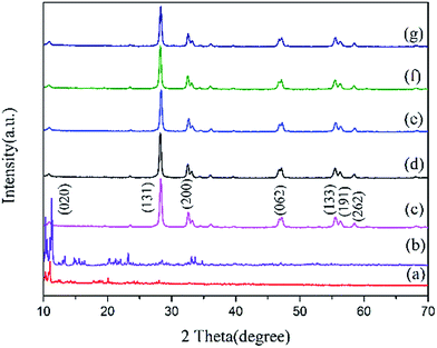 |
| | Fig. 1 XRD patterns of (a) MIL-100(Fe), (b) MIL-100(Fe)-simulated, (c) Bi2MoO6, (d) Bi2MoO6–MIL-100(Fe)-3, (e) Bi2MoO6–MIL-100(Fe)-6, (f) Bi2MoO6–MIL-100(Fe)-9, (g) Bi2MoO6–MIL-100(Fe)-12. | |
3.2 Morphology
Fig. 2 shows the SEM images of Bi2MoO6, MIL-100(Fe) and their composites Bi2MoO6–MIL-100(Fe)-9, respectively. The rough microspheres composed of nanoparticles with dozens of nanometers are observed for Bi2MoO6 (Fig. 2a). And the diameter of the microsphere is 1–3 μm. In the Fig. 2b, the pure MIL-100(Fe) exhibited regular octahedron morphology with diameter ranging from 2 to 4 μm. As for the Bi2MoO6–MIL-100(Fe)-9 composite (Fig. 2c and d), it can be observed that MIL-100(Fe) serves as a support and the nanoparticles of Bi2MoO6 grow on the surface of MIL-100(Fe). Meanwhile, there is no aggregation of Bi2MoO6 nanoparticles on MIL-100(Fe), indicating that the interaction between Bi2MoO6 and MIL-100(Fe) is strong. Besides, the regular octahedron morphology of MIL-100(Fe) was not changed in the composite, the result demonstrated the structure of MIL-100(Fe) was not destroyed in the synthesized process of Bi2MoO6–MIL-100(Fe) composite. The Energy Dispersive Spectroscopy (EDS) patterns of Bi2MoO6–MIL-100(Fe)-9 composite revealed the existence of Bi, Mo, C, O and Fe. The tight interaction between the Bi2MoO6 and MIL-100(Fe) can enhance the photocatalytic activity.
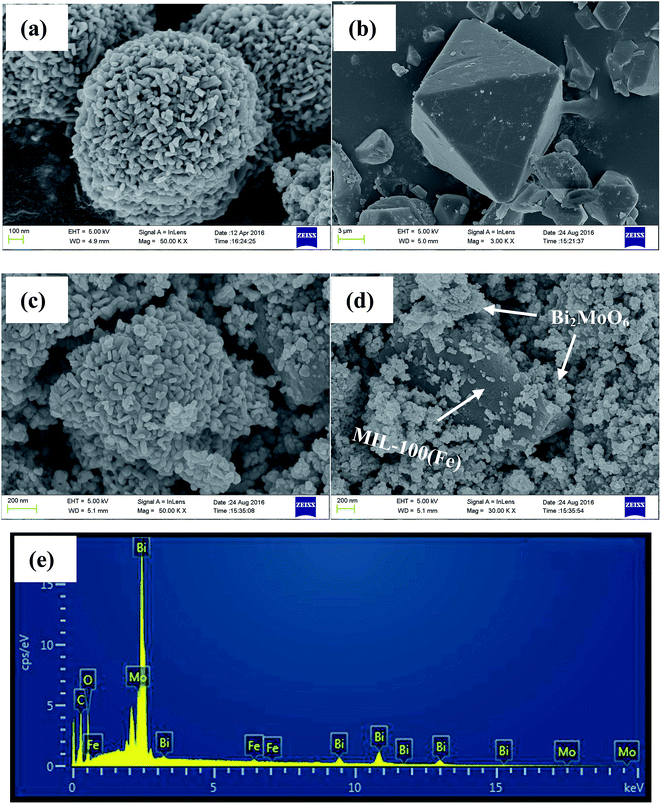 |
| | Fig. 2 SEM images of (a) pure Bi2MoO6, (b) pure MIL-100(Fe), (c) and (d) Bi2MoO6–MIL-100(Fe)-9 composites, and (e) EDS patterns of the Bi2MoO6–MIL-100(Fe)-9 composites. | |
The TEM and HRTEM images of Bi2MoO6–MIL-100(Fe)-9 sample were shown in Fig. 3a and b, respectively. The TEM image shows the Bi2MoO6 nanoparticles on the MIL-100(Fe) surface, and the microstructures of the Bi2MoO6–MIL-100(Fe)-9 sample. The HRTEM images clearly indicated the resolved lattice fringes of 0.315, 0.406 and 0.192 nm, which correspond to the (131), (040) and (062) planes of orthorhombic phase of Bi2MoO6, respectively. The results indicate that the formation of composites of Bi2MoO6 and MIL-100(Fe) can promote faster separation of photoinduced charge carriers and improve photocatalytic activities.
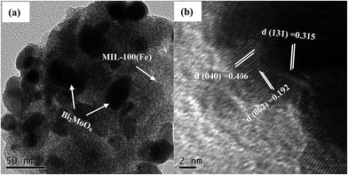 |
| | Fig. 3 (a) TEM and (b) HRTEM images of Bi2MoO6–MIL-100(Fe)-9. | |
3.3 XPS analysis
The surface chemical composition of Bi2MoO6–MIL-100(Fe)-9 was analyzed by XPS. Fig. 4 shows XPS survey spectra and high-resolution XPS spectra of the Bi 4f, Mo 3d, O 1s, Fe 2p and C 1s regions for the sample of Bi2MoO6–MIL-100(Fe)-9. The survey spectra indicated that Bi, Mo, O, Fe and C exist on the surface of Bi2MoO6–MIL-100(Fe)-9, and no impurities were detected, in accordance with EDS result. In the Bi 4f spectrum, two peaks at 159.2 eV and 164.5 eV are attributed to Bi 4f7/2 and Bi 4f5/2 of Bi3+, respectively.33 In the Mo 3d spectrum, peaks at 232.5 eV and 235.6 eV were ascribed to Mo 3d5/2 and Mo 3d3/2 of Mo6+, respectively.34 The O 1s peak of the composite at 530.1 eV is observed, which was relate to Mo–O.35 The Fe 2p peak was associated with the binding energy at 712.1 eV, which are characteristic of Fe(III) in MIL-100(Fe).31 In addition, the C 1s peaks at 288.8 and 284.7 eV arises from MIL-100(Fe) and external carbon contamination, respectively.36 In summary, the XPS spectra analysis confirms that Bi2MoO6–MIL-100(Fe) composites have been synthesized successfully.
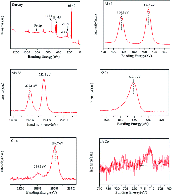 |
| | Fig. 4 XPS survey spectra of Bi2MoO6–MIL-100(Fe)-9 and high-resolution XPS spectra of the Bi 4f, Mo 3d, O 1s, Fe 2p and C 1s. | |
3.4 BET analysis
Brunauer–Emmett–Teller (BET) surface area of the as-synthesized samples were examined by nitrogen adsorption–desorption isotherms at 77 K. It can be found that the introduction of MIL-100(Fe) can significantly affect the BET surface area of samples. Compared with pure Bi2MoO6, the BET surface area (SBET) of Bi2MoO6–MIL-100(Fe) composites obviously increased, from 9.3172 m2 g−1 to 109.6347 m2 g−1. The larger surface area of photocatalysts can provide more surface active sites and promote charge carriers transport easily, contributing to an enhanced photocatalytic performance.37 Therefore, MIL-100(Fe) in synthesized composites may play the key role in enhancing the photocatalytic activity.
3.5 PL analysis
Photoluminescence (PL) spectra were used to investigate the transfer and separation efficiency of photogenerated electron–hole pairs.38 As we all known, the lower PL intensity indicated a lower recombination of photoinduced charge carriers. The PL spectra of Bi2MoO6, MIL-100(Fe) and Bi2MoO6–MIL-100(Fe)-9 for excitation wavelength 605 nm are shown in Fig. 5. The main emission peaks around 460–500 nm appear for three photocatalysts, and the emission peak of Bi2MoO6–MIL-100(Fe)-9 is lower than the Bi2MoO6 and MIL-100(Fe). The resulting of the PL spectra indicated the addition of MIL-100(Fe) into semiconductor Bi2MoO6 is contributed to the separation of photo-generated electron–hole pairs.
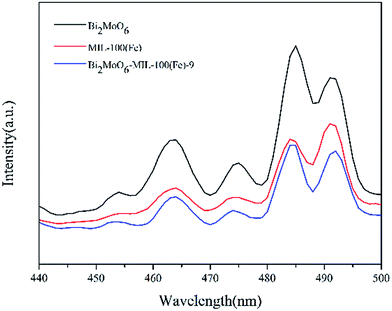 |
| | Fig. 5 PL spectra of Bi2MoO6, MIL-100(Fe) and Bi2MoO6–MIL-100(Fe)-9, recorded at an excitation wavelength of 605 nm. | |
3.6 UV-vis DRS
The UV-vis diffusive reflectance spectra (UV-vis DRS) of Bi2MoO6, MIL-100(Fe) and Bi2MoO6–MIL-100(Fe)-9 photocatalysts were shown in Fig. 6a. The adsorption of three photocatalytic samples are located in visible light region. The absorption edge of Bi2MoO6 is 485 nm, and MIL-100(Fe) exhibits absorption edge in 550 nm. As the composites of two different semiconductors, the Bi2MoO6–MIL-100(Fe)-9 exhibits absorption edges at 510 nm. Furthermore, the band gap energies of Bi2MoO6 and MIL-100(Fe) could be calculated by the following equation:39| | |
α(hv) = A(hv − Eg)1/2
| (2) |
where α, v, Eg, and A are the absorption coefficient, the light frequency, the energy band gap of semiconductor, and a constant, respectively. According to eqn (2), the band-gap of photocatalysts can be estimated from plots of (αhv)2 versus energy (hv). In the Fig. 6b, the band gaps of as-synthesized Bi2MoO6, MIL-100(Fe) and Bi2MoO6–MIL-100(Fe)-9 are estimated to be 2.58, 2.50 and 2.38 eV, respectively. The resulting confirmed that Bi2MoO6 can match up with MIL-100(Fe) perfectly, which contributes to the separation of the electron–hole pairs.
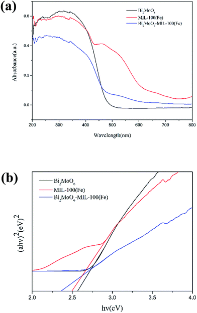 |
| | Fig. 6 (a) UV-vis diffuse reflectance spectra (DRS) of Bi2MoO6, MIL-100(Fe) and Bi2MoO6–MIL-100(Fe)-9; (b) the plots of (ahv)n/2 vs. photon energy (hv) for the band-gap energies of Bi2MoO6, MIL-100(Fe) and Bi2MoO6–MIL-100(Fe)-9. | |
3.7 Photocatalytic activity
The photocatalytic activities of as-prepared photocatalysts were evaluated by the degradation of RhB under visible light irradiation. The RhB adsorption and photodegradation process of different photocatalysts are shown in Fig. 7a. Before the visible light irradiation, the absorption–desorption balance has been reached between the catalyst and RhB for 30 min absorption process. Fig. 7a shows that RhB was hardly decomposed by photolysis without any catalysts under visible light irradiation. The adsorption rate of pure Bi2MoO6 and MIL-100(Fe) are 15.36% and 44.39% in the dark, respectively. The adsorption rate of MIL-100(Fe) is very high, but it has low photocatalytic performance for RhB under the visible-light irradiation. Meanwhile, pure Bi2MoO6 shows low photocatalytic activity for RhB degradation, the photodegradation rate is 62.56%. However, the addition of MIL-100(Fe) improved the photocatalytic activities of Bi2MoO6–MIL-100(Fe) composites significantly. The photocatalytic activities of Bi2MoO6–MIL-100(Fe) composites enhanced, with the increase of content of MIL-100(Fe). When the addition of MIL-100(Fe) reached 9%, Bi2MoO6–MIL-100(Fe) composites demonstrated greater degradation performance, up to 88.46% RhB removed in 120 min. Meanwhile, the absorption of RhB in Bi2MoO6–MIL-100(Fe)-9 increased to 22.25% compared with pure Bi2MoO6, indicating that the introduction of MIL-100(Fe) promoted the increase of adsorption ability of catalysts. Besides, the physical mixture Bi2MoO6–MIL-100(Fe)-9(M) composite exhibited lower activity than Bi2MoO6–MIL-100(Fe)-9, it may be due to the instable Bi2MoO6–MIL-100(Fe) heterojunctions. The result indicated that the presence of MIL-100(Fe) enhanced light absorption, separation of photo-generated electron–hole pairs, and increased surface area. The enhanced photocatalytic performance is contributed to the heterostructure between Bi2MoO6 and MIL-100(Fe). In addition, Fig. 7b shows the corresponding first-order kinetics plot by the equation:40where C0 and C are the RhB concentrations in solution at times 0 and t, respectively, and k is the apparent first-order rate constant. According to the equation, the rates of RhB degradation are 0.00881 min−1, 0.01248 min−1, 0.01314 min−1, 0.02174 min−1, 0.01494 min−1 and 0.01201 min−1 for pure Bi2MoO6, Bi2MoO6–MIL-100(Fe)-3, Bi2MoO6–MIL-100(Fe)-6, Bi2MoO6–MIL-100(Fe)-9, Bi2MoO6–MIL-100(Fe)-12 and Bi2MoO6–MIL-100(Fe)-9(M). The rate of RhB degradation of Bi2MoO6–MIL-100(Fe)-9 is higher than other photocatalysts. The result indicated that the interaction between Bi2MoO6 and MIL-100(Fe) can improve the photocatalytic performance, and the photocatalytic activity is significantly enhancing with the increase of the mass ratio of MIL-100(Fe). The photocatalytic activity reached the maximum value, when the mass ratio of MIL-100(Fe) is 9%.
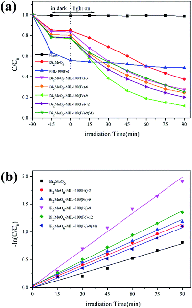 |
| | Fig. 7 (a) Photodegradation of as-prepared samples for RhB. (b) The kinetic constants (k) of photocatalytic for RhB. | |
The mineralization rate of RhB over photocatalysts was detected by Total Organic Carbon (TOC) test. The TOC results (Fig. 8) indicated that only 67.42% of RhB is mineralized over Bi2MoO6–MIL-100(Fe)-9 after 120 min and more irradiation time is needed to make the substrate completely mineralized. After 210 min, the mineralization rate of RhB over Bi2MoO6–MIL-100(Fe)-9 can only reach 87.29%. But the mineralization rate of RhB over Bi2MoO6–MIL-100(Fe)-9 is higher than that over Bi2MoO6 and Bi2MoO6–MIL-100(Fe)-9(M). The above results show that Bi2MoO6–MIL-100(Fe) composites exhibited much higher photocatalytic performance than pure Bi2MoO6 under visible light irradiation.
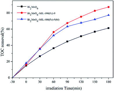 |
| | Fig. 8 TOC removal process of RhB solution. | |
3.8 The proposed photocatalytic mechanism
3.8.1 Analysis of active species. The active species including holes (h+), superoxide radical (˙O2−), and hydroxyl radicals (˙OH) are possibly impact factors for the photodegradation of organic pollutants. It is important to carry out the trapping experiments for confirming the main active species generated over Bi2MoO6–MIL-100(Fe) composites. In the detection, EDTA-2Na (ref. 33) and tert-butyl alcohol (TBA)41 are used as the scavengers of holes (h+) and hydroxyl radical (˙OH). The p-benzoquinone (BQ)42 and N2 (ref. 43) are used as the scavenger of superoxide radical (˙O2−). As shown in Fig. 9, the photocatalytic degradation of RhB over Bi2MoO6–MIL-100(Fe)-9 was slightly affected by the addition of TBA (1 mL). However, the photocatalytic activity of Bi2MoO6–MIL-100(Fe)-9 was significantly inhibited by the addition of EDTA-2Na (0.5 mmol). Similarly, the degradation rate was obviously decreased after the addition of BQ (0.5 mmol). In the word, active species including h+ and ˙O2− play the crucial roles in the photodegradation of pollutants.
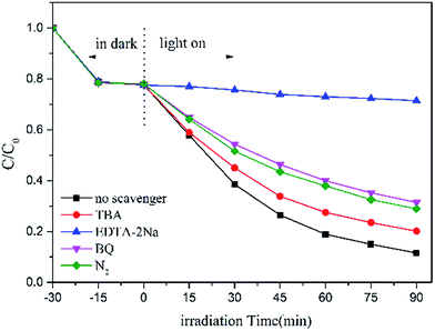 |
| | Fig. 9 Photocatalytic degradation of RhB over Bi2MoO6–MIL-100(Fe)-9 with different scavengers. | |
To test the role of dissolved O2 in the reaction process, enough nitrogen (N2) was bubbled into the suspension to ensure that the degradation system was operated under anoxic conditions. In the presence of N2, the photocatalytic activity of catalyst was inhibited under the same condition. This result means that dissolved O2 is a vital factor in RhB removal over Bi2MoO6–MIL-100(Fe) composites, which affects the formation of ˙O2− via direct reduction of O2 and the formation of ˙OH via indirect reduction of O2.44
3.8.2 The proposed photocatalytic mechanism. It is well-known that the photocatalytic performances of catalysts rely on the transfer, separation and generation of electron–hole pairs. In our study, the interaction between Bi2MoO6 and MIL-100(Fe) can promote the separation of photogenerated charge carries and improve the photodegradation rate under visible light. In order to understand the photocatalytic mechanism of the Bi2MoO6–MIL-100(Fe) composites in depth, the initial energy band structures of Bi2MoO6 and MIL-100(Fe) were estimated. The band edges of Bi2MoO6 and MIL-100(Fe) were calculated by the following empirical formulas:45where EVB is the valence band (VB) edge potential, ECB is the conduction band edge potential, Eg is the band gap energy of the semiconductor, X is the electronegativity of the semiconductor, which is the geometric mean of the electronegativity of the constituent atoms, and the X values for Bi2MoO6 and MIL-100(Fe) were calculated to be 5.55 and 5.10 eV, respectively. Ee is the energy of free electrons on the hydrogen scale (about 4.5 eV). The Eg of Bi2MoO6 and MIL-100(Fe) are estimated as 2.58 and 2.50 eV. According to above formulas, the VB and CB edge potentials of Bi2MoO6 are located at −0.24 and 2.34 eV, respectively. The VB and CB edge potentials of MIL-100(Fe) are determined to be −0.65 and 1.85 eV, respectively.On the basis of above band energy level analysis and active species trapping detection, the possible proposed mechanism was discussed as illustrated in Scheme 1. Under the visible light irradiation, both Bi2MoO6 and MIL-100(Fe) can be excited for generation of electrons (e−) and holes (h+) in their CB and VB. The photo-generated electrons in the CB of MIL-100(Fe) transfer to the CB of Bi2MoO6 via the heterojunction structure. At the same, the holes in the VB of Bi2MoO6 can migrate to the VB of MIL-100(Fe), hence promoting the separation of photoinduced electron–holes pairs. O2 molecules in solution adsorbed onto catalysts form superoxide radical (˙O2−) via electron transfer from MIL-100(Fe) to O2, since the conduction band potential of MIL-100(Fe) (−0.65 eV versus NHE) was more negative than the standard redox potentials of (E(O2/˙O2−) = −0.33 eV versus NHE). Similarly, the standard redox potentials of (E(H2O/˙OH) = +2.8 eV versus NHE) was more positive than the VB of the Bi2MoO6 (2.34 eV) and MIL-100(Fe) (1.85 eV), thus it is difficult to oxidize the adsorbed H2O into ˙OH for photo-generated. The part h+ radicals reacted with H2O molecules in solution to generate reactive hydroxyl (˙OH) and H+ ions. Moreover, the adsorbed RhB onto Bi2MoO6–MIL-100(Fe) can be excited to RhB* under visible-light irradiation.46 Then the electrons from RhB* are transformed into photocatalyst to form RhB+˙. The RhB (or RhB+˙) is finally photodegraded by the reactive species (O2, ˙OH) or h+ to generate H2O and CO2. According to above discussion, the process can be described as follows:
| | |
MIL-100(Fe) + hv → MIL-100(Fe)(e− + h+)
| (6) |
| | |
RhB + hv → RhB* → RhB+˙ + e−
| (7) |
| | |
Bi2MoO2 + e− → Bi2MoO2(e− + h+)
| (8) |
| | |
MIL-100(Fe)(e−) + O2 → ˙O2− + MIL-100(Fe)
| (9) |
| | |
˙O2− + RhB/RhB+˙ → other products → CO2 + H2O
| (10) |
| | |
˙OH + RhB/RhB+˙ → other products → CO2 + H2O
| (11) |
| | |
h+ + RhB/RhB+˙ → other products → CO2 + H2O
| (12) |
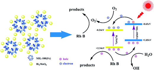 |
| | Scheme 1 Photocatalytic degradation mechanism over Bi2MoO6–MIL-100(Fe) heterostructure under visible light irradiation. | |
3.9 Regeneration and reusability
It is significant to evaluate the reusable performance and stability of photocatalysts for practical applications.47 To investigate the stability of Bi2MoO6–MIL-100(Fe)-9, we carried out 4 times recycle experiment to degrade RhB under the same conditions. After each cycle, the photocatalyst was centrifuged, filtered, washed and dried at 60 °C for 12 h. As shown in Fig. 10a, after four cycles, the degradation rate of RhB decreased from 88.46% to 84.91%, the photocatalyst removed organic pollutants with only a slight loss of activity. After being used four times, as shown in Fig. 10b, the XRD patterns of Bi2MoO6–MIL-100(Fe)-9 composite before and after catalytic reaction further demonstrated that the structure of the Bi2MoO6–MIL-100(Fe) composites remain intact. Besides, the ICP-AES analysis showed that the leaching Fe and Bi ions from the photocatalysts in the reaction solution were 0.143 mg L−1 and less than 0.01 mg L−1 after cycles reaction respectively. The leaching ions concentration is very low compared with the concentration of catalysts (1000 mg L−1), which is negligible. Therefore, the as-prepared Bi2MoO6–MIL-100(Fe)-9 composites show excellent stability and reusability in the visible light photochemical applications.
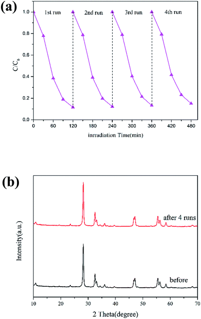 |
| | Fig. 10 (a) Cycling runs for photocatalytic degradation of RhB over Bi2MoO6–MIL-100(Fe)-9 under visible light irradiation; (b) XRD patterns of Bi2MoO6–MIL-100(Fe)-9 before and after reactions. | |
4. Conclusions
In summary, Bi2MoO6–MIL-100(Fe) photocatalysts have been successfully fabricated by facile solvothermal method in this work for the first time. The characterizations of Bi2MoO6–MIL-100(Fe) composites were confirmed by XRD, SEM/EDS, TEM, and XPS. The as-synthesized Bi2MoO6–MIL-100(Fe) photocatalyst exhibited excellent photocatalytic performance in degradation of RhB under visible light. The optimal mass ratio of MIL-100(Fe) in the composite is 9% for the excellent synergistic effect between Bi2MoO6 and MIL-100(Fe). The presence of MIL-100(Fe) in the composites enhanced light absorption, and increased surface area. The photo-generated h+ and ˙O2− in Bi2MoO6–MIL-100(Fe) composites are proved to be the main active species over the photodegradation. The enhanced photocatalytic performance is mainly attributed to perfect matched energy band of heterostructure, improved photoinduced charge carriers transfer efficiency, and inhibited photo-generated electron–hole recombination. Our study confirmed that the introduction of MIL-100(Fe) into semiconductor Bi2MoO6 can improve the photocatalytic activity and stability of Bi2MoO6-based photocatalysts, it may be a promising candidate in synthesis of novel catalysts.
Acknowledgements
This work was supported by the State Key Laboratory of Lake Science and Environment (2016SKL011).
References
- H. Li, J. Liu, W. Hou, N. Du, R. Zhang and X. Tao, Appl. Catal., B, 2014, 160–161, 89–97 CrossRef CAS.
- M. Andersson, L. Österlund, S. Ljungström and A. Palmqvist, J. Phys. Chem. B, 2002, 106, 10674–10679 CrossRef CAS.
- G. Li, X. Nie, Y. Gao and T. An, Appl. Catal., B, 2016, 180, 726–732 CrossRef CAS.
- Z. F. Yin, L. Wu, H. G. Yang and Y. H. Su, Phys. Chem. Chem. Phys., 2013, 15, 4844–4858 RSC.
- L. Zhang, T. Xu, X. Zhao and Y. Zhu, Appl. Catal., B, 2010, 98, 138–146 CrossRef CAS.
- S. Cao, X. Liu, Y. Yuan, Z. Zhang, Y. Liao, J. Fang, S. C. J. Loo, T. C. Sum and C. Xue, Appl. Catal., B, 2014, 147, 940–946 CrossRef CAS.
- Y. Xu and W. Zhang, Dalton Trans., 2013, 42, 1094–1101 RSC.
- S. Martha, A. Nashim and K. M. Parida, J. Mater. Chem. A, 2013, 1, 7816 CAS.
- M. M
![[a with combining cedilla]](https://www.rsc.org/images/entities/char_0061_0327.gif) czka, L. Macalik, K. Hermanowicz, L. Kepiński and J. Hanuza, J. Raman Spectrosc., 2010, 41, 1289–1296 CrossRef.
czka, L. Macalik, K. Hermanowicz, L. Kepiński and J. Hanuza, J. Raman Spectrosc., 2010, 41, 1289–1296 CrossRef. - K. Dai, D. Li, L. Geng, C. Liang and Q. Liu, Mater. Lett., 2015, 160, 124–127 CrossRef CAS.
- X. Lin, X. Guo, D. Liu, Q. Wang, H. Zhai and L. Chang, Mater. Res. Bull., 2015, 63, 72–79 CrossRef CAS.
- Z. Dai, F. Qin, H. Zhao, J. Ding, Y. Liu and R. Chen, ACS Catal., 2016, 6, 3180–3192 CrossRef CAS.
- Y. Feng, X. Yan, C. Liu, Y. Hong, L. Zhu, M. Zhou and W. Shi, Appl. Surf. Sci., 2015, 353, 87–94 CrossRef CAS.
- J. Lv, K. Dai, J. Zhang, L. Geng, C. Liang, Q. Liu, G. Zhu and C. Chen, Appl. Surf. Sci., 2015, 358, 377–384 CrossRef CAS.
- T. Yan, M. Sun, H. Liu, T. Wu, X. Liu, Q. Yan, W. Xu and B. Du, J. Alloys Compd., 2015, 634, 223–231 CrossRef CAS.
- P. Wang, Y. Ao, C. Wang, J. Hou and J. Qian, Carbon, 2012, 50, 5256–5264 CrossRef CAS.
- A. Phuruangrat, S. Putdum, P. Dumrongrojthanath, N. Ekthammathat, S. Thongtem and T. Thongtem, Mater. Sci. Semicond. Process., 2015, 34, 175–181 CrossRef CAS.
- L. Shen, S. Liang, W. Wu, R. Liang and L. Wu, J. Mater. Chem. A, 2013, 1, 11473 CAS.
- M. D. Allendorf, R. J. T. Houk, L. Andruszkiewicz, A. A. Talin, J. Pikarsky, A. Choudhury, K. A. Gall and P. J. Hesketh, J. Am. Chem. Soc., 2008, 130, 14404–14405 CrossRef CAS PubMed.
- R. B. Getman, Y. Bae, C. E. Wilmer and R. Q. Snurr, Chem. Rev., 2012, 112, 703–723 CrossRef CAS PubMed.
- P. Horcajada, R. Gref, T. Baati, P. K. Allan, G. Maurin, P. Couvreur, G. Férey, R. E. Morris and C. Serre, Chem. Rev., 2012, 112, 1232–1268 CrossRef CAS PubMed.
- L. Yang, P. Ravindran, P. Vajeeston and M. Tilset, Phys. Chem. Chem. Phys., 2012, 14, 4713 RSC.
- I. Luz, F. X. Llabrés I Xamena and A. Corma, J. Catal., 2010, 276, 134–140 CrossRef CAS.
- D. Jiang, T. Mallat, F. Krumeich and A. Baiker, J. Catal., 2008, 257, 390–395 CrossRef CAS.
- M. Dan-Hardi, C. Serre, T. Frot, L. Rozes, G. Maurin, C. Sanchez and G. Férey, J. Am. Chem. Soc., 2009, 131, 10857–10859 CrossRef CAS PubMed.
- H. Wang, X. Yuan, Y. Wu, G. Zeng, H. Dong, X. Chen, L. Leng, Z. Wu and L. Peng, Appl. Catal., B, 2016, 186, 19–29 CrossRef CAS.
- J. He, Z. Yan, J. Wang, J. Xie, L. Jiang, Y. Shi, F. Yuan, F. Yu and Y. Sun, Chem. Commun., 2013, 49, 6761 RSC.
- F. Ke, L. Wang and J. Zhu, Nano Res., 2015, 8, 1834–1846 CrossRef CAS.
- X. Wang, J. Liu, S. Leong, X. Lin, J. Wei, B. Kong, Y. Xu, Z. Low, J. Yao and H. Wang, ACS Appl. Mater. Interfaces, 2016, 8, 9080–9087 CAS.
- D. Esken, S. Turner, C. Wiktor, S. B. Kalidindi, G. Van Tendeloo and R. A. Fischer, J. Am. Chem. Soc., 2011, 133, 16370–16373 CrossRef CAS PubMed.
- R. Liang, S. Luo, F. Jing, L. Shen, N. Qin and L. Wu, Appl. Catal., B, 2015, 176–177, 240–248 CrossRef CAS.
- D. Kim, H. Kim and D. Cho, Catal. Commun., 2016, 73, 69–73 CrossRef CAS.
- Y. Feng, X. Yan, C. Liu, Y. Hong, L. Zhu, M. Zhou and W. Shi, Appl. Surf. Sci., 2015, 353, 87–94 CrossRef CAS.
- Z. Zhao, W. Zhang, Y. Sun, J. Yu, Y. Zhang, H. Wang, F. Dong and Z. Wu, J. Phys. Chem. C, 2016, 120, 11889–11898 CAS.
- H. Li, Q. Deng, J. Liu, W. Hou, N. Du, R. Zhang. T. Xutang, 2014.
- F. Zhang, Y. Jin, J. Shi, Y. Zhong, W. Zhu and M. S. El-Shall, Chem. Eng. J., 2015, 269, 236–244 CrossRef CAS.
- L. Shen, S. Liang, W. Wu, R. Liang and L. Wu, J. Mater. Chem. A, 2013, 1, 11473 CAS.
- D. Yue, T. Zhang, M. Kan, X. Qian and Y. Zhao, Appl. Catal., B, 2016, 183, 1–7 CrossRef CAS.
- J. Lv, K. Dai, J. Zhang, L. Geng, C. Liang, Q. Liu, G. Zhu and C. Chen, Appl. Surf. Sci., 2015, 358, 377–384 CrossRef CAS.
- S. Fang, C. Ding, Q. Liang, Z. Li, S. Xu, Y. Peng and D. Lu, J. Alloys Compd., 2016, 684, 230–236 CrossRef CAS.
- J. Cao, B. Xu, H. Lin, B. Luo and S. Chen, Dalton Trans., 2012, 41, 11482 RSC.
- X. Xiong, L. Ding, Q. Wang, Y. Li, Q. Jiang and J. Hu, Appl. Catal., B, 2016, 188, 283–291 CrossRef CAS.
- Y. Yao, J. Qin, H. Chen, F. Wei, X. Liu, J. Wang and S. Wang, J. Hazard. Mater., 2015, 291, 28–37 CrossRef CAS PubMed.
- R. Jiang, H. Y. Zhu, J. B. Li, F. Q. Fu, J. Yao, S. T. Jiang and G. M. Zeng, Appl. Surf. Sci., 2016, 364, 604–612 CrossRef CAS.
- J. Tian, P. Hao, N. Wei, H. Cui and H. Liu, ACS Catal., 2015, 5, 4530–4536 CrossRef CAS.
- X. Yuan, H. Wang, Y. Wu, G. Zeng, X. Chen, L. Leng, Z. Wu and H. Li, Appl. Organomet. Chem., 2016, 30, 289–296 CrossRef CAS.
- S. Martha, A. Nashim and K. M. Parida, J. Mater. Chem. A, 2013, 1, 7816 CAS.
|
| This journal is © The Royal Society of Chemistry 2017 |
Click here to see how this site uses Cookies. View our privacy policy here.  Open Access Article
![[thin space (1/6-em)]](https://www.rsc.org/images/entities/char_2009.gif) :
:![[thin space (1/6-em)]](https://www.rsc.org/images/entities/char_2009.gif) 0.67
0.67![[thin space (1/6-em)]](https://www.rsc.org/images/entities/char_2009.gif) :
:![[thin space (1/6-em)]](https://www.rsc.org/images/entities/char_2009.gif) 2
2![[thin space (1/6-em)]](https://www.rsc.org/images/entities/char_2009.gif) :
:![[thin space (1/6-em)]](https://www.rsc.org/images/entities/char_2009.gif) 0.6
0.6![[thin space (1/6-em)]](https://www.rsc.org/images/entities/char_2009.gif) :
:![[thin space (1/6-em)]](https://www.rsc.org/images/entities/char_2009.gif) 2.77 was synthesized in a Teflon-lined stainless steel autoclave at 150 °C for 24 h. Then the orange solid was centrifuged, washed with ethanol and hot water for several times, and finally dried overnight 60 °C under vacuum.
2.77 was synthesized in a Teflon-lined stainless steel autoclave at 150 °C for 24 h. Then the orange solid was centrifuged, washed with ethanol and hot water for several times, and finally dried overnight 60 °C under vacuum.


![[a with combining cedilla]](https://www.rsc.org/images/entities/char_0061_0327.gif) czka, L. Macalik, K. Hermanowicz, L. Kepiński and J. Hanuza, J. Raman Spectrosc., 2010, 41, 1289–1296 CrossRef.
czka, L. Macalik, K. Hermanowicz, L. Kepiński and J. Hanuza, J. Raman Spectrosc., 2010, 41, 1289–1296 CrossRef.


