 Open Access Article
Polystyrene core–silica shell composite particles: effect of mesoporous shell structures on oxide CMP and mechanical stability
Yang Chen *a,
Ailian Chenb and
Jiawei Qina
aSchool of Materials Science and Engineering, Changzhou University, Changzhou, 213164, China. E-mail: cy.jpu@126.com
bSchool of Mechanical Engineering, Changzhou University, Changzhou, 213164, China
First published on 20th January 2017
Abstract
Organic/inorganic composite particles with a core–shell structure exhibit potential applications in chemical mechanical polishing/planarization (CMP) for mechanically challenging materials (copper and low-k dielectrics etc.). In this work, the spherical composites comprised of polystyrene (PS) cores and mesoporous silica (mSiO2) shells were synthesized through a self-assembly of cetyltrimethylammonium bromide and silicate oligomers combined with a selective etching strategy. The composites with sponge-like (composites-A) or worm-like shells (composites-B) were obtained by adjusting the stirring rate in the synthesis processes. The oxide CMP performances of the composites with different shell structures were compared in terms of surface finishing and material removal rate (MRR). Polishing results showed that the particles consisted of mesoporous shells (composites-A and -B) and presented a lower surface roughness and higher MRR than those of the composites with CTAB/SiO2 nonoporous shells (composites-C), indicating that the mSiO2 shells contributed to the reduction of indentation depth (surface roughness) and improvement of MRR. The average root-mean-square (RMS) roughness and MRR for composites-A were 2.65 Å and 65 nm min−1, respectively, which were comparable to the measured values for composites-B (2.07 Å and 75 nm min−1). As confirmed by FESEM, the sponge-like shells in some of composites-A peeled off, whereas the radial mSiO2 shells for most of composites-B were not disrupted. An improved organization of mesochannels in the silica shells is beneficial to the enhanced mechanical and structural stability of PS/mSiO2 composite particles during CMP applications.
1. Introduction
Chemical mechanical polishing/planarization (CMP)1,2 has emerged as an efficient technique for achieving ultra-smooth and global planarity of wafer surfaces. It has been commonly recognized that CMP is a triboelectrochemical process dominated by mechanical and chemical-assisted wear. In a typical CMP process, a wafer is placed face-down onto a rotating carrier and pressed against a rotating polishing pad. The polishing slurry containing chemical components and abrasive particles is delivered on top of the pad. The slurry chemistry is aimed to create a soft corrosion layer, which is subsequently removed by abrasive particles.3Silica, alumina and ceria particles are the most commonly used abrasive materials for CMP applications. The major advantage of the silica particles is that they are chemically inert and can be easily modified by simple chemical reactions.4 The material removal rate (MRR), defectivity, and surface flatness and roughness are critically influenced by the structure, shape, size, hardness (H) and elastic modulus (E) of abrasive particles. For the optimization and improvement of CMP performances, many efforts have been attempted to the design and synthesis of novel abrasive particles with special mechanical and/or chemical properties, including doped abrasives, core/shell structured composites, and porous abrasives. For example, Lei and coworkers prepared Cu-,5 La-,6 and Ce-doped colloidal SiO2 particles7 for the improving CMP behaviors for sapphire substrates. X-ray photoelectron spectroscopy analysis confirmed that solid-state chemical reactions between doped particles and sapphire surfaces occurred, which was contributed to promoting the chemical effects in CMP process and resulting in an improved MRR.
Organic/inorganic composite particles with a core–shell structure exhibit potential applications in chemical mechanical polishing/planarization (CMP) for mechanically challenging materials (copper and low-k dielectrics etc.). Armini and coworkers8,9 improved the CMP behaviors for copper and SiO2 dielectric layer using the composite polymer–silica core–shell submicrometer particles. Particularly, the types of surface defects after polishing were classified and quantified by using a confocal review station. Our group focused on the synthesis of the composites containing polymer (polystyrene (PS) or polymethylmethacrylate) cores and ceria shells,10,11 and their applications in oxide-CMP. For porous abrasives, Chen and coworkers12 investigated the CMP effects of various porous abrasives such as α-alumina and alumina/ceria composites on Al-NiP hard disk substrate. In our previous work,13 the submicrometer spherical mesoporous silica abrasives with controlled sizes were synthesized and introduced into oxide-CMP applications.
In order to combine the advantages of porous abrasives and core/shell structured composites, we reported the applications of the PS/mSiO2 (ref. 14) and sSiO2/mSiO2 composite particles15 consisting PS (or solid silica) cores and mesoporous silica shells in oxide CMP process. It was confirmed that these novel abrasive particles exhibit an improved polishing behavior by comparison with conventional solid silica particles. The reduced surface roughness and enhanced MRR might result from the optimization of the physical and/or chemical environments between abrasives and substrates. More successful applications demand a detailed understanding of the relationship between meso-silica structures and CMP performances. Inspired by our previous works, the PS/mSiO2 composites with sponge-like or radial worm-like porous silica shells were prepared in the presented work. The aim of this current study is to undertake an in-depth investigation of the effect of mesoporous shell structures on oxide CMP behaviors of the PS/mSiO2 composite particles. Moreover, the mechanical stability of the composites with different shell structures was further evaluated by FESEM. This approach would provide a basis for understanding the actual role of the composite abrasives with porous shells in the material removal process during CMP.
2. Experimental section
2.1 Materials
The monomers of styrene (St) were obtained from Shanghai Chemical Reagent Co. (China), and purified by treatment with 5 wt% aqueous NaOH solutions to remove the inhibitor prior to use.Tetraethylorthosilicate (TEOS), cetyltrimethylammonium bromide (CTAB), ethanol, poly(vinylpyrrolidone) (PVP, Mw = 30![[thin space (1/6-em)]](https://www.rsc.org/images/entities/char_2009.gif) 000), ammonia aqueous solution (28 wt%), NaOH and NH4NO3 were purchased from Shanghai Chemical Reagent Co. (China). 2,2′-Azobis(2-methylpropionamidine)dihydrochloride (AIBA) was obtained from Aladdin chemical Co., Ltd. All chemicals were analytical grade and used without further purification. Deionized (DI) water was used in all experiments.
000), ammonia aqueous solution (28 wt%), NaOH and NH4NO3 were purchased from Shanghai Chemical Reagent Co. (China). 2,2′-Azobis(2-methylpropionamidine)dihydrochloride (AIBA) was obtained from Aladdin chemical Co., Ltd. All chemicals were analytical grade and used without further purification. Deionized (DI) water was used in all experiments.
2.2 Synthesis of core/shell structured PS/mSiO2 composites
The PVP-modified PS microspheres (262 ± 4 nm) were synthesized by soap-free microemulsion polymerization as described elsewhere.16 In brief, St (8.5 g), DI water (150 g) and PVP (2.0 g) were added to a four-necked flask equipped with a magnetic stirrer, a thermometer with a temperature controller, a N2 inlet and a water-cooled reflux condenser. The mixture was deoxygenated by bubbling N2 for 30 min under magnetic stirring (300 rpm) at room temperature, then heated at 70 °C, followed by addition of AIBA (0.2 g, dissolved in 15 g DI water) to initiate polymerization. Finally, the reaction was performed with vigorously stirring at 70 °C for 24 h under N2 protection.For the preparation of the PS/mSiO2 composites, the mesoporous silica layers were coated on the PS microspheres via a modified Stöber approach using CTAB as a template. The directed surface sol–gel process of TEOS on the PS cores was performed in the presence of the CTAB surfactant. In a typical procedure, 3 g of PS microemulsion were dispersed in 120 g of DI water after ultrasonic treatment for 15 min, and then added into the solution containing 47.4 g of ethanol, 0.384 g of CTAB, and 1.08 g of ammonia aqueous solution. The mixture was stirred mechanically for 30 min at room temperature to prepare a homogeneous solution, and then 1.2 g of TEOS was added dropwise. The reaction was maintained for 2 h at 30 °C with constant stirring. The products were collected by centrifugation and washed with DI water and ethanol several times. The obtained samples were dispersed in NH4NO3/ethanol solution (10 mg mL−1) and refluxed at 60 °C for 2 h, and then centrifuged and washed with ethanol and water several times, respectively. After complete removal of the CTAB surfactant, the core/shell structured PS/mSiO2 composites were obtained. In our experiments, the samples prepared with a stirring speed of 350 and 150 rpm were denoted as composites-A and -B, respectively. For comparison, the composites-B samples without removal of CTAB were also named as composites-C.
X-ray diffraction (XRD) measurement was performed with a Rigaku D/max X-ray diffractometer using Cu radiation. The particle size and morphology were determined with a field emission scanning electron microscopy (FESEM) system (SUPRA-55, ZEISS) at an acceleration voltage of 15 kV. The surfaces of the samples were coated with gold prior to the observation. The average particle sizes were calculated from the diameters of more than 50 particles in FESEM images. Transmission electron microscopy (TEM) micrographs were obtained with a JEOL-JEM2100 TEM system using an acceleration voltage of 200 kV. The STEM-EDX elemental mapping images were obtained using an FEI Talos 200S TEM system operating at 300 kV. The nitrogen adsorption–desorption isotherms were measured using a Micromeritics ASAP 2020 apparatus at 77 K. The pore diameters were calculated using the Barrett–Joyner–Halenda (BJH) method for the desorption branch. The specific surface areas were calculated using the Brunauer–Emmett–Teller (BET) plot for the adsorption branch. Thermogravimetric analyses (TGA) were performed on a NETZSCH 209 F1 apparatus from room temperature to 700 °C at 10 °C min−1 in nitrogen.
2.3 Oxide CMP experiments with composites-based slurries
Thermal oxide (ca. 1200 nm in thickness) films grown on 4 in. silicon substrates were obtained from Changzhou Huacheng Changban Microelectronics Limited Company. Each of these wafers was cut into several pieces (2.0 cm × 2.0 cm), which were then used for polishing tests.The obtained composite particles were used to prepare the polishing slurries with an appropriate pH (8) and particle concentration. All pH adjustments were performed using 0.1 M NaOH. For the preparation of slurries, a shaker was applied for 15 min and the solid content was fixed at 1 wt%. The slurries were then used to finish thermally grown silicon oxide wafers, using a Struers TegraForce-1/TrgraPol-15 rotary polisher. The rotation speeds of the head and platen were set at 120 and 90 rpm, respectively. The pressure of the carrier was 4 psi and the polishing time was 1 min. The slurry flow rate was 100 mL min−1. The selected experimental conditions were the result of a design of the experiment. The material removal rate (MRR, nm min−1) of the oxide films was measured by characterizing the thickness of the substrates before and after CMP using an ellipsometer (ELLIP-SR-II, Shanghai Bright Enterprise Development Co., Ltd.). The reported values of MRR were obtained by averaging over three runs.
The oxide surfaces were examined by using a Digital Instruments Multimode Nanoscope Atomic Force Microscope (AFM, equipped with a Dimension V controller, using Tap300Al-G silicon probes in tapping mode), which provided an overview of the topographies, residual particles, scratches and profile curves of the wafer surfaces before and after finishing. We determined the root-mean-square roughness (RMS) and average roughness (Ra) values at five randomly selected locations (from the top, bottom, left, right, and center parts of the samples) on the wafer surfaces and repeated the process on 3 different finished wafers. To explore the mechanical stability of the mSiO2 shells of the composites during CMP processes, the residual particles adhered to the substrate surfaces (before post cleaning) were also observed by FESEM.
3. Results and discussion
3.1 Characterization of composite particles
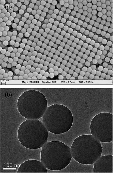
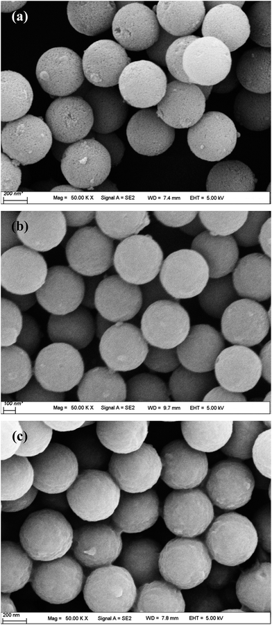
The particle size and morphology of the PVP-modified PS sphere (containing a PS core and a PVP shell) prepared by soap-free microemulsion polymerization method were examined by FESEM and TEM, as shown in Fig. 1. Obviously, the bare PVP-modified PS particles display the morphology of smooth and homogeneously distributed spheres with a particle size distribution of 262 ± 4 nm. All the microspheres are well dispersed without agglomeration, revealing that PVP is an excellent dispersion stabilizer agent.16 As reported by Graf and coworkers,17 the adsorbed PVP (as a coupling agent) was contributed to the formation of silica shells on the surfaces of PS particles.Fig. 2 demonstrates the FESEM morphologies of the composites-A, -B and -C. After coating mSiO2 or SiO2/CTAB layers, these composites also present uniform spherical in shape and the outer surfaces of composites become relative rough. Separate particles can hardly be observed in these SEM images, suggesting that the coverage was uniformly formed on the PS cores. As shown in Fig. 2a, many pores and cave-ins can be clearly observed in the mSiO2 shells, indicating that the composites-A exhibits a relatively loosened appearance by comparison with composites-B (Fig. 2b) and -C (Fig. 2c). As estimated by FESEM, the particle size of composites-A is 411 ± 7 nm, which is comparable to the composites-B (408 ± 6 nm). Compared with uncoated PS cores (around 262 nm), the thickness of mSiO2 shells can be estimated to be around 75 nm. However, the composites-C exhibits a slightly large particle size of 440 ± 5 nm, which may be attributed to the residual untreated CTAB micelles in the shells or the shrinkage of porous silica shells during the treatment with NH4NO3/ethanol solution.
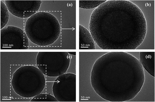
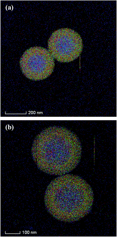
The silica shell structures of the obtained composite particles were further analyzed by TEM. The low-magnification TEM images of composites-A (Fig. 3a) and -B (Fig. 3c) exhibit uniform spherical morphology without aggregation and the electron contrast between the cores and the shells confirms the formation of a distinct core–shell structure. In addition, the STEM-EDX elemental mapping analyses (Fig. 4) clearly differentiate the core–shell structures of the as-prepared composites. The porous silica shells are about 72 ± 4 (composites-A) and 68 ± 3 nm (composites-B) in thickness estimated from the TEM images by comparing the PS core size before and after silica coating. As confirmed by high-magnification TEM images, the composites-A (Fig. 3b) presents a sponge-like mesopores and lack of organized structures, while the silica shells of composites-B (Fig. 3d) are consisted of radial worm-like mesopore channels. In our experiments, a relatively low stirring speed (150 rpm) is contributed to the formation of the radial mesoporous silica shells on the PS microspheres through the co-assembly of CTAB and silicate oligomers derivated from the hydrolysis of TEOS in the basic solution and the subsequent removal of CTAB templates. As reported by Yue and coworkers,18 the increase of stirring rate (shearing force) helped to expand the mesopores size, but too fast stirring could cause an inhomogeneous pore expansion. In our experiments, a relatively high-speed stirring also resulted in an enhanced dynamic shearing force, which might cause a relatively poor organization of mesochannels with a larger pore size and a broad pore size distribution.
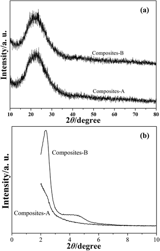
The XRD patterns of composites-A and -B are presented in Fig. 5. A halo of peak at around 2θ = 23° can be observed in the wide-angle XRD patterns (Fig. 5a), indicating the existence of amorphous PS and silica. The low-angle XRD pattern (Fig. 5b) of the composites-B shows a sharp peak in the diffractogram in around 2θ = 2–3° and a weak intensity peak in 2θ = 4–5°, which indicates that these samples exhibit a typical feature of radial mesoporous structures.19 In the case of composites-A, the distinct diffraction peaks cannot be found in Fig. 5b, while the major peak is shifted to a low angle and the peak relative intensity is significantly reduced. The intensity decrease indicates a loss of long range order of mesoporous channels for the mSiO2 shells,20 which can also reflect in XRD intensities. The TEM observations and XRD results reveal that the obtained composites-B present an improved organization of mesochannels in silica shells by comparison with the composites-A samples.
Nitrogen adsorption–desorption measurements for composites-A and -B samples were performed in order to investigate the detailed information about the mesoporous shell structures. The isotherms of the composites-B present two well-defined adsorption steps (Fig. 6a). The first step at an intermediate relative pressure (P/P0 = 0.2–0.4) reveals the features of typical type IV isotherms with H2 hysteresis and is related to capillary condensation of nitrogen inside the intra-mesopores.21 The second and small step at a high relative pressure (P/P0 = 0.9–1.0) corresponds to the filling of the large pores among the composites-A microspheres and is associated to a small proportion of textural porosity. The absence of a hysteresis loop within a relative pressure of 0.2–0.4 and the narrow BJH pore distribution curve (Fig. 6b) suggest a cylindrical uniformity of the intra-mesopores. The structural characteristics of the as-synthesized composites-A and -B particles are summarized in Table 1. As calculated from the BJH model on the adsorption branch, the mesopore size and pore volume is found to be around 2.7 nm and 0.57 cm3 g−1, respectively. In addition, the BET specific surface area is determined to be 876.9 m2 g−1. For the composites-A samples, the first adsorption step shifts toward a higher relative pressure (Fig. 5c), and the isotherms correspond to the type IV hysteresis with a distinct H3 hysteresis loop,22 indicating that composites-A microspheres have ink-bottle-type pores in which large cavities are connected by narrow windows. As shown in Fig. 5d, the broad pore size distribution can be observed by comparison with composites-B. These nitrogen adsorption–desorption results are consistent with the information extracted from TEM and XRD.
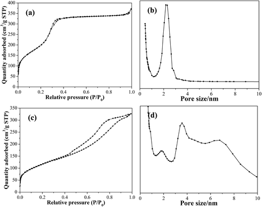 | ||
| Fig. 6 Nitrogen adsorption–desorption isotherms and pore size distribution curves of composite-B (a, b) and -A (c, d). | ||
| Samples | Shell thickness (nm) | BET surface area (m2 g−1) | Pore volume (cm3 g−1) | Pore size (nm) |
|---|---|---|---|---|
| Composites-A | 72 ± 4 | 422.0 | 0.51 | 5.1 |
| Composites-B | 68 ± 3 | 876.9 | 0.57 | 2.7 |
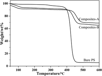
Fig. 7 presents the TGA curves of the bare PVP-modified PS spheres and composite particles. Three weight-losses below 250 °C, 250–450 °C and 450–600 °C correspond to the evaporation of physically adsorbed water and residual solvent, the decomposition of the polymeric PVP-modified PS spheres, and the decomposition of the silica-bonded groups, respectively. In addition, no signal corresponding to the decomposition of CTAB in the range of 220–230 °C (ref. 14) is observed, confirming that CTAB is completely removed by washing with NH4NO3/ethanol solution. Compared to the original PVP-modified PS spheres, the TGA curves of composites-A and -B particles slightly moved toward a higher temperature, implying that the strong interaction between PS cores with silica shells.23 Therefore, the silica coating resulted in an improved thermal stability of the materials.
3.2 Topography analysis of substrates
The surface morphologies of the wafers were analyzed by tapping mode AFM. The scale of AFM height images was fixed at 2 nm in order to emerge clearly the scratches and residual particles of substrate surfaces. The corresponding line scans obtained from the AFM images more clearly illustrate that CMP changes the surface topographies. One diagonal in the two-dimensional (2D) AFM images was selected in the measurements in order to facilitate the subsequent comparison and analysis. The average MRR and surface roughness values of the substrates before and after polishing are listed in Table 2.| Samples | Roughness (Å) | MRR (nm min−1) | |
|---|---|---|---|
| Ra | RMS | ||
| Before CMP | 6.70 | 8.47 | — |
| After CMP with composites-A | 1.93 | 2.65 | 65 |
| After CMP with composites-B | 1.62 | 2.07 | 75 |
| After CMP with composites-C | 2.05 | 3.16 | 47 |
As shown in Fig. 8a, the typical 2D AFM image of original substrate shows a rough surface with an average RMS roughness of 8.47 Å over a 25 μm2 area. In AFM height images, the dark areas show the low points, while bright areas represent the high points. Therefore, a uniform color in AFM images suggests a better surface planarization. The corresponding profile curve (Fig. 8b) reveals that the topographical variation is in a range of −1.6 nm to +1.7 nm.
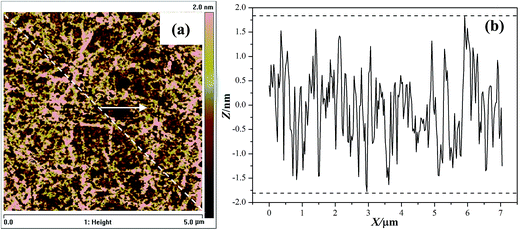 | ||
| Fig. 8 Two-dimensional AFM image (a) and corresponding line scan profile (b) of the original wafer surface. | ||
After CMP with composite particles, flat and smooth surfaces without distinct scratches are achieved (Fig. 9a1–a3). The composites-A and -B exhibit the comparable average RMS surface roughness values of 2.65 and 2.07 Å, respectively, determined within a 5 μm × 5 μm area. In addition, an average MRR of 65 (composites-A) and 75 nm min−1 (composites-B) was achieved, as shown in Table 2. The average RMS roughness and MRR data confirm that there was no statistically significant difference between the composites-A and -B. RMS roughness is a commonly used statistical measure for comparison of surface. However, RMS roughness values may be misleading because they do not describe the horizontal spatial distribution of surface features.24 For example, surfaces with a wide, hilly topography can have an RMS roughness identical to a surface with narrower and sharper peaks as long as the hills or peaks deviate from the mean plane by the same amount on average. The profile curves show that the topographical variation of the substrates after finishing with the composites-A and -B reduce to a range of ±0.60 nm (Fig. 9b1) and ±0.45 nm (Fig. 9b2), respectively. A lower topographical variation suggests a better surface planarization degree. Although both surfaces are described as ultrasmooth according to the roughness measurements, they also differ in the topographical variation and planarization. Fig. 8 shows the corresponding three-dimensional (3D) AFM images of the substrate surfaces before and after CMP. It can be clearly observed that many nano-sized asperity peaks exist in the initial wafer (Fig. 10a). After CMP with composites-A (Fig. 10b) and -B (Fig. 10c), the height of the nano-sized asperity peaks is evidently reduced, indicating an improved surface quality and planarization.
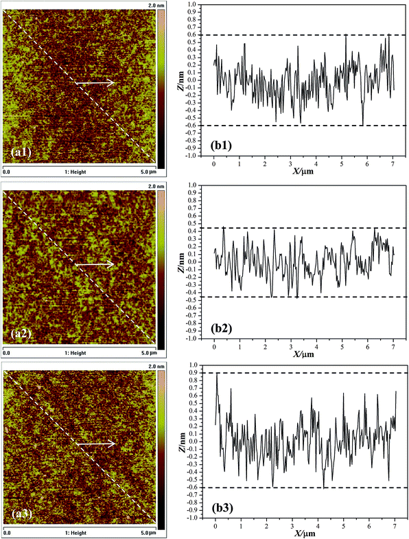 | ||
| Fig. 9 Two-dimensional AFM images and corresponding line scan profiles of the substrates after finishing with composites-A (a1, b1), -B (a2, b2) and -C (a3, b3). | ||
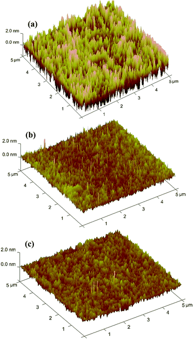 | ||
| Fig. 10 Three-dimensional AFM images of the substrates (a) before and after finishing with (b) composites-A and (c) -B. | ||
The substrate surface after finishing with composites-C reveals an average RMS roughness of 3.26 Å, which is higher than composites-B (2.07 Å). In addition, the composites-C also produces a lower average MRR (47 nm min−1) and larger topographical variation of −0.60 to +0.90 nm (Fig. 9b3) than composites-A (75 nm min−1, ±0.45 nm) under the same CMP conditions. For the preparation of composites-C, the CTAB surfactants were not treated and removed with NH4NO3/ethanol mixture. As a result, the shells of composites-C are consisted of both CTAB micelles and silica oligomers, while the shells of composites-C are composed of porous silica with radial mesochannels. It is commonly recognized that the porous materials exhibit a much lower elastic modulus (E) and surface hardness (H), and much higher specific areas than solid materials.25–27 As reported in literature,28 the E value of the ordered mesoporous silica films (∼4 nm in pore size) was found to be around 11.4 GPa, which was much lower than solid silica (around 76 GPa (ref. 29)). Meanwhile, the H value of the core/shell structured ZIF-8@mSiO2 (∼75 nm in shell thickness) composite particles was measured by nanoindentation and estimated to be around 1.2 GPa,30 which was also much lower than solid silica. Therefore, the porous shells may be contributed to the reduction of E and H values for the core–shell structured hybrids with a fixed polymer core. Correspondingly, the composites-C with nonporous shell may also exhibit a relatively high E and H values than those of composites-A and -B with porous shells.
As proposed by Armini and coworkers,31 the abrasive particles with relatively low E and H values may deform elastically during CMP processes, which is be beneficial to the decrease of the contact stress between a particle and a wafer. Chen and coworkers32 developed a novel mathematical CMP model, in which the deformation of an abrasive particle was taken into consideration. It was found that the particle deformation was beneficial to the reduction of the indentation depth of an abrasive onto a substrate surface, resulting in a reduced surface roughness. As a result, the substrate polished with composites-C demonstrates a larger surface roughness and topographical variation than those of composites-B.
In a typical oxide-CMP process, it is commonly recognized that a chemically reacted soft layer on the substrate surface is formed by the chemical effects of the basic slurry and then removed mechanically by abrasive particles.3,33,34 An enhanced chemical action is help of promoting the formation of the modified layer, which is also contributed to the improvement of MRR in oxide CMP processes. It has been confirmed that mesoporous materials with abundant pore structures and high surface areas show the remarkable adsorption properties in aqueous solution.35,36 Therefore, the composites-B consisted of mesoporous silica shells with a high specific area may adsorb more active components in polishing slurry, which is beneficial to enhancing the interfacial reaction activity and chemical corrosion action.13,14 As a result, the composite-B presents an improved MRR by comparison with composite-C.
3.3 Mechanical stability of composite particles
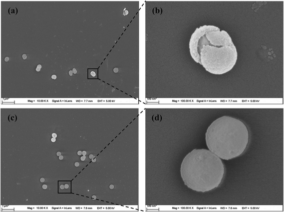
The material removal during a CMP process is a mechanical friction and wear action incorporated with a chemical corrosion action. For achieving the damage-free finished surfaces with high efficiency, it is important and critical to control and understand the interfacial contact and abrasion behavior between abrasive particles and substrate surfaces.37 The observations for used abrasive particles may provide more related information, and is in favor of revealing the actual material removal mechanism in CMP. In our previous work,38 the structural stability of the core/shell PS/SiO2 composites with different shell morphology during CMP was investigated by AFM. The composites with smooth shells composed of amorphous silica network exhibited an enhanced structural stability by compared to the composites with rough shells consisted of separate SiO2 nanoparticles. Successful applications of composite abrasives in CMP applications require a more comprehensive evaluation. Therefore, the influence of mesoporous shell structures of the composite-A and -B particles on their mechanical stability was further evaluated by FESEM observations.Fig. 11 shows the FESEM images of the substrate surfaces after CMP with composites-A and -B prior to post-cleaning. From the low-magnification FESEM images (Fig. 11a and c), it can be clearly observed that some residual particles adhere to the uncleaned surfaces. The high-magnification image (Fig. 11b) reveals that some of composites-A particles are broken, and the silica shells peel off while the internal cores are exposed. However, the adhered composites-B particles (Fig. 11d) maintain a well-defined core–shell structure. As revealed by FESEM observation of the composite particles, for the most of the composites-B, the mesoporous silica shells are not disrupted by the shear forces and chemistry during the CMP process.
To our knowledge, there are few reports about the mechanical property measurements for the spherical meso-silica particles or the composites with meso-silica shells. The mechanical property and stability of mesoporous silica film or bulk materials have been extensively investigated in the past decade. For example, the E values of disordered (sponge-like) and ordered (honeycomb-like, ∼3 nm in pore size) mesoporous silica films were measured Williford and coworkers39 using a Hysitron Picoindenter mounted on an AFM with a standard Berkowitz diamond indenter tip. The E of the disordered porous film was determined to be around 3.2 GPa, which was comparable to the ordered film (around 3.5 GPa). In addition, the E data was much lower than the solid silica film (around 26.5 GPa). Furthermore, Jauffrès and coworkers28 investigated the fracture characteristics of thin silica films containing different types of porosity (ordered meso, random macro and hierarchical) by AFM nano-indentation. The mechanical behavior of the films was further analyzed by AFM imaging of the residual indent marks. It was found that the mesoporous silica films exhibit a classical elasto-plastic behavior and a significant elastic recovery. However, the macroporous and hierarchically porous silica films presented a very short elastic deformation followed by the brittle collapse of the macropores. These results also suggested that an enhanced organization of mesoporous films was contributed the improvement of their mechanical and structural stability. In this work, compared to the composites-A with sponge-like mesopores, the composites-B with radial worm-like mesochannels exhibits an improved structural stability during contact processes among wafers, abrasives and pads.
4. Conclusions
In summary, we have prepared the core/shell structured PS/mSiO2 composites with different mesoporous shell structures by adjusting the stirring rate in synthesis processes. As confirmed by TEM and XRD, the silica shells for composites-A were consisted of sponge-like mesopores and lack of organized structures, while the shells for composites-B exhibited radial worm-like mesochannels. The particle size of PS cores was 262 ± 4 nm, and the mesoporous shell thickness is 72 ± 4 (composites-A) and 68 ± 3 nm (composites-B). Nitrogen adsorption–desorption measurements show that the BET specific surface area for composites-A and -B were 422.0 and 876.9 m2 g−1, respectively. As calculated by BJH model, the composites-B demonstrated a narrow pore size distribution with an average pore diameter of 2.7 nm. Oxide-CMP results indicated that the mesoporous silica shells were contributed to an improved surface quality and an enhanced MRR. The average RMS roughness and MRR of composites-A are 2.65 Å and 65 nm min−1, respectively, which were comparable to those of composites-B (2.07 Å and 75 nm min−1). As revealed by FESEM observation of the residual particles adhered to substrate surfaces after CMP, the composites-B with ordered meso-silica shells presented an improved mechanical and structural stability than the composites-A with disordered mesoporous shells. Further work on determination of mechanical properties and chemical adsorption properties is ongoing in our group.Acknowledgements
The work was supported financially by the National Natural Science Foundation of China (51205032, 51405038, 51575058), and the Priority Academic Program Development of Jiangsu Higher Education Institutions (PAPD).References
- H. K. Sung, C. Wang and N. Y. Kim, Mater. Sci. Semicond. Process., 2015, 40, 516–522 CrossRef CAS.
- N. Tatsumi, K. Harano, T. Ito and H. Sumiya, Diamond Relat. Mater., 2016, 63, 80–85 CrossRef CAS.
- Y. G. Wang, Y. Chen, F. Qi, D. Zhao and W. W. Liu, Tribol. Int., 2016, 93, 11–16 CrossRef CAS.
- L. Zhang, M. D'Acunzi, M. Kappl, G. Auernhammer and D. Vollmer, Langmuir, 2009, 25, 2711–2717 CrossRef CAS PubMed.
- H. Lei and Q. Gu, J. Mater. Sci.: Mater. Electron., 2015, 26, 10194–10200 CrossRef CAS.
- H. Lei and K. Tong, Precis. Eng., 2016, 44, 124–130 CrossRef.
- H. Lei, K. Tong and Z. Wang, Mater. Chem. Phys., 2016, 172, 26–31 CrossRef CAS.
- S. Armini, C. M. Whelan, M. Moinpour and K. Maex, J. Electrochem. Soc., 2008, 155, H401–H406 CrossRef CAS.
- S. Armini, C. M. Whelan, M. Moinpour and K. Maex, J. Electrochem. Soc., 2009, 156, H18–H26 CrossRef CAS.
- Y. Chen, Z. Li and N. Miao, Tribol. Int., 2015, 82, 211–217 CrossRef CAS.
- A. L. Chen, Z. F. Zhang, X. L. Li and Y. Chen, J. Mater. Sci.: Mater. Electron., 2016, 27, 2919–2925 CrossRef CAS.
- S. Chen, H. Lei and R. Chen, J. Vac. Sci. Technol., B: Nanotechnol. Microelectron.: Mater., Process., Meas., Phenom., 2014, 31, 021804 Search PubMed.
- Y. Chen, Z. F. Li, J. W. Qin and A. L. Chen, J. Mater. Sci., 2016, 51, 5811–5822 CrossRef CAS.
- Y. Chen, J. W. Qin, Y. Y. Wang and Z. F. Li, J. Nanopart. Res., 2015, 17, 363 CrossRef.
- A. L. Chen, Y. Chen, Y. Y. Wang and J. W. Qin, J. Alloys Compd., 2016, 663, 60–67 CrossRef CAS.
- K. Shibuya, D. Nagao, H. Ishii and M. Konno, Polymer, 2014, 55, 535–539 CrossRef CAS.
- C. Graf, D. L. J. Vossen, A. Imhof and A. van Blaaderen, Langmuir, 2003, 19, 6693–6700 CrossRef CAS.
- Q. Yue, J. Li, W. Luo, Y. Zhang, A. A. Elzatahry, X. Wang, C. Wang, W. Li, X. Cheng, A. Alghamdi, A. M. Abdullah, Y. Deng and D. Zhao, J. Am. Chem. Soc., 2015, 137, 13282–13289 CrossRef CAS PubMed.
- N. Varga, M. Benkő, D. Sebők, G. Bohus, L. Janovák and I. Dékány, Microporous Mesoporous Mater., 2015, 213, 134–141 CrossRef CAS.
- S. Liu, H. Zhang, X. Meng, Y. Zhang, L. Ren, F. Nawaz, J. Liu, Z. Li and F. S. Xiao, Microporous Mesoporous Mater., 2010, 136, 126–131 CrossRef CAS.
- E. Yu, I. Galiana, R. Martínez-Máñez, P. Stroeve, M. D. Marcos, E. Aznar, F. Sancenón, J. R. Murguía and P. Amorós, Colloids Surf., B, 2015, 135, 652–660 CrossRef CAS PubMed.
- X. N. Wei, H. L. Wang, Z. D. Li, Z. Q. Huang, H. P. Qi and W. F. Jiang, Appl. Surf. Sci., 2016, 372, 108–115 CrossRef CAS.
- M. Chen, S. Zhou, L. Wu, S. Xie and Y. Chen, Macromol. Chem. Phys., 2005, 206, 1896–1902 CrossRef CAS.
- M. S. Miller, M. Ferrato, A. Niec, M. C. Biesinger and T. B. Carmichael, Langmuir, 2014, 30, 14171–14178 CrossRef CAS PubMed.
- Y. Jing, Z. Jing and E. H. Ishida, Ind. Eng. Chem. Res., 2013, 52, 17865–17870 CrossRef CAS.
- Y. Hiratan, T. Shimonosono, T. Sameshima and S. Sameshima, Ceram. Int., 2014, 40, 2315–2322 CrossRef.
- Z. Chen, X. Wang, F. Giuliani and A. Atkinson, Acta Mater., 2015, 89, 268–277 CrossRef CAS.
- D. Jauffrès, C. Yacou, M. Verdier, R. Dendievel and A. Ayral, Microporous Mesoporous Mater., 2011, 140, 120–129 CrossRef.
- S. Romeis, J. Paul, P. Herre, D. Ligny, J. Schmidt and W. Peukert, Scr. Mater., 2015, 108, 84–87 CrossRef CAS.
- Z. Li and H. C. Zeng, J. Am. Chem. Soc., 2014, 136, 5631–5639 CrossRef CAS PubMed.
- S. Armini, I. U. Vakarelski, C. M. Whelan, K. Maex and K. Higashitani, Langmuir, 2007, 23, 2007–2014 CrossRef CAS PubMed.
- X. Chen, Y. Zhao and Y. Wang, Appl. Surf. Sci., 2012, 258, 8469–8474 CrossRef CAS.
- K. Qin, B. Moudgil and C. W. Park, Thin Solid Films, 2004, 446, 277–286 CrossRef CAS.
- C. C. Wei, J. H. Horng, A. C. Lee and J. F. Lin, Wear, 2011, 270, 172–180 CrossRef CAS.
- J. B. Joo, J. Park and J. Yi, J. Hazard. Mater., 2009, 168, 102–107 CrossRef CAS PubMed.
- F. de Clippel, A. Harkiolakis, T. Vosch, X. Ked, L. Giebeler, S. Oswald, K. Houthoofd, J. Jammaer, G. Van Tendeloo, J. A. Martens, P. A. Jacobs, G. V. Baron, B. F. Sels and J. F. M. Denayer, Microporous Mesoporous Mater., 2011, 144, 120–133 CrossRef CAS.
- D. Guo, G. Xie and J. Luo, J. Phys. D: Appl. Phys., 2014, 47, 013001–013025 CrossRef.
- A. L. Chen, W. B. Mu and Y. Chen, Appl. Surf. Sci., 2014, 290, 433–439 CrossRef CAS.
- R. E. Williford, X. S. Li, R. S. Addleman, G. E. Fryxell, S. Baskaran, J. C. Birnbaum, C. Coyle, T. S. Zemanian, C. Wang and A. R. Courtney, Microporous Mesoporous Mater., 2005, 85, 260–266 CrossRef CAS.
| This journal is © The Royal Society of Chemistry 2017 |

