 Open Access Article
Creative Commons Attribution 3.0 Unported Licence
Rapid electrochemical synthesis of HKUST-1 on indium tin oxide
Li-Long Jiangb,
Xiangzhou Zenga,
Mengkai Lia,
Man-Qing Wanga,
Tong-Yu Sua,
Xiao-Chun Tianc and
Jing Tang*a
aKey Laboratory of Analysis and Detection Technology for Food Safety, Ministry of Education, College of Chemistry and Chemical Engineering, Fuzhou University, Fuzhou, 350108, Fujian Province, P. R. China. E-mail: jingtang@fzu.edu.cn; Fax: +86 59122866165; Tel: +86 59122866165
bNational Engineering Research Center for Chemical Fertilizer Catalyst at Fuzhou University College of Chemistry and Chemical Engineering, Fuzhou University, Fuzhou, 350108, Fujian Province, P. R. China
cDepartment of Chemistry, College of Chemistry and Chemical Engineering, Xiamen University, Xiamen, 361005, Fujian Province, P. R. China. E-mail: tianxiaochun@hotmail.com
First published on 30th January 2017
Abstract
We synthesized a HKUST-1 metal–organic framework (MOF) on indium tin oxide (ITO) using an electrodeposited Cu film. The electrodeposited Cu/ITO was used as a source of Cu ions, which were linked with benzene-1,3,5-tricarboxylic acid on the ITO surface to form HKUST-1. Synthesized HKUST-1/ITO was characterized by X-ray diffraction (XRD), Raman spectroscopy and scanning electron microscopy (SEM), which showed that the morphology of the HKUST-1 framework was nearly octahedral. Our results also revealed that the growth of HKUST-1 depended on the potential and synthesis time used. This method can be applied to fabricate ordered patterns of HKUST-1 on ITO substrates, offering a new way to grow MOFs on many other kinds of conductive substrates.
1. Introduction
In the last 20 years, many researchers have focused on developing metal–organic frameworks (MOFs), which are a new class of porous material that consist of 1D, 2D, or 3D networks of metal ions linked together by organic bridging ligands.1,2 HKUST-1 (CuBTC, BTC = benzene-1,3,5-tricarboxylic acid) is an interesting MOF with a 3D network containing large pores with square cross sections (9 × 9 Å), desirable for gas separation and purification.3 Studies have also been performed on its electrochemical synthesis, behavior and applications.4–6 Traditional means of synthesizing HKUST-1 include room temperature synthesis, conventional electric (CE) heating, microwave (MW) heating, electrochemistry (EC), and mechanochemistry (MC).Another interesting synthesis method is that proposed by Müller et al.: direct anodic dissolution of metal in an electrolyte containing an organic linker. Cu electrodes have been commonly used for this methods to synthetize HKUST-1.7,8 In the electrochemical synthesis process, the electrolyte composition, current density, and applied potential have been shown to influence the morphology of the resultant HKUST-1.9 However, MOF films should be able to be coated on a variety of substrates for different applications, because integrated, patterned, or sensitive devices are often not fabricated on pure Cu substrates.10
Herein, we introduce a novel process to synthesize HKUST-1 on a conductive indium tin oxide (ITO) substrate which consists two electrochemical steps. Since the Cu ions are produced near the Cu/ITO substrate, the HKUST-1 crystals can be directly formed on the ITO surface. The as synthesized HKUST-1 was characterized by X-ray diffraction (XRD), Raman spectroscopy and scanning electron microscopy (SEM). This method was applied to fabricate ordered patterns of HKUST-1 on ITO substrates and could be used as a new way to grow MOFs on various conductive substrates.
2. Experimental
We used analytical-grade reagents and ultrapure water throughout our experiments. Tetrabutyl ammonium perchlorate (TBAP) (≥99.0%) used for electrochemical analysis was purchased from Sigma-Aldrich, and BTC (98%) was obtained from Aladdin. ITO (1.1 mm thickness, resistivity < 30 Ω cm−1) obtained from Xiamen Ito Photoelectricity Ind Co., Ltd. (Xiamen, China) was used as the electrode and to support the HKUST-1.We performed all electrochemical experiments with a standard three-electrode cell on a CHI614D or a CHI842B electrochemistry workstation (Shanghai ChenhuaAppatatus Corporation, China). A saturated calomel electrode (SCE) and a Pt slice were used as the reference electrode and the auxiliary electrode, respectively. The sample solutions were purged with high-purity nitrogen for at least ten minutes to remove oxygen prior to the experiments. The ITO (working area of ∼1 × 1 cm) was ultrasonically cleaned with acetone, alcohol, and ultrapure water successively.
The process to synthesize HKUST-1 on the ITO substrate using two electrochemical steps. The first step is to electrodeposit a thin film of Cu on ITO using a solution of 5 mmol L−1 CuSO4 + 0.1 mol L−1 K2SO4 for 500 s. The second step is forming the HKUST-1 by anodically dissolving the Cu film in a 3![[thin space (1/6-em)]](https://www.rsc.org/images/entities/char_2009.gif) :
:![[thin space (1/6-em)]](https://www.rsc.org/images/entities/char_2009.gif) 1 v/v solution of EtOH and H2O containing 25 mmol L−1 BTC as a linking agent and 50 mmol L−1 TBAP as a supporting electrolyte, and the anodically dissolving time is 100 s.
1 v/v solution of EtOH and H2O containing 25 mmol L−1 BTC as a linking agent and 50 mmol L−1 TBAP as a supporting electrolyte, and the anodically dissolving time is 100 s.
The morphology and microstructure of the synthesized Cu/ITO and HKUST-1/ITO were characterized by SEM (NOVA NANO SEM 230) and Raman spectroscopy (inVia Renishaw, UK). The XRD patterns of the Cu/ITO over the range of 10–90° were obtained with a Philips X'Pert Pro MPD (Holland) powder diffraction system using Co Kα radiation with a 2θ step size of 0.02°. XRD measurements were also taken for 5–20° using a Rigaku diffractometer with an accelerating voltage of 40 kV, Cu Kα radiation, a 2θ/θ step size of 0.01°, and a step width of 0.5°.
3. Results and discussion
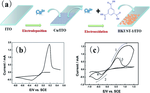
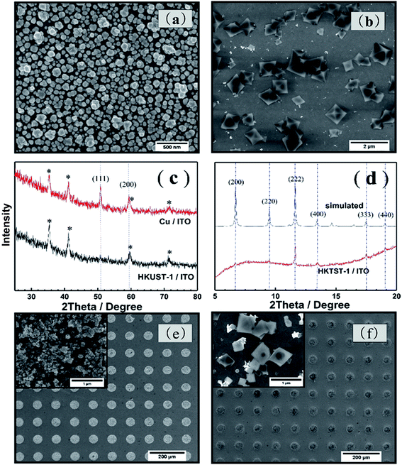
The process to synthesize HKUST-1 on the ITO substrate is using two electrochemical steps. As Fig. 1(a) shows, the first step of this method is to electrodeposit a thin film of Cu on ITO. The second step is forming the HKUST-1 by anodically dissolving the Cu film. A thin layer of Cu/ITO was synthesized by electro-deposition and used as a source for synthesizing HKUST-1/ITO. The Cu/ITO substrate was prepared by electrodepositing Cu at a constant potential of −0.8 V for 500 s. Fig. 1(b) shows the electrochemical behavior of ITO in this solution. The reduction of Cu2+ onto the ITO begins at 0 V and reaches a peak at −0.3 V, limited by diffusion. The obtained Cu/ITO was used as a substrate to synthesize HKUST-1/ITO. As Fig. 1(c) shows, when the potential scans in the positive direction relative to the open circuit potential (0.01 V), the oxidation current increases obviously and reaches a peak at 1.2 V. This behavior indicates that the electrodeposited Cu oxidizes to Cu2+ and then reacts with BTC in the electrolyte to generate HKUST-1 on the ITO surface, as shown in the first curve of Fig. 1(c). However, HKUST-1 on ITO is not electrochemically stable when the potential is scanned in the negative direction (curve 2). The current generated by the reduction of Cu2+ in HKUST-1 increases to a maximum current at −0.6 V. When the potential scans in the positive direction again (curve 3), the Cu redissolves and quickly links with the BTC to redeposit as HKUST-1. The reduction current is smaller in curve 4 than in curve 2 because of redissolved Cu2+ ions used for the HKUST-1 formation and some Cu2+ diffusing into the bulk solution till all Cu will be dissolved. It seems that the amount of HKUST-1 decreases after many potential cycles between −1.0 V and 1.5 V vs. SCE. Therefore, we chose to synthesize HKUST-1 using a fixed 1.5 V potential.Fig. 2(a) shows the morphology of the electrodeposited Cu/ITO. The Cu film consist of uniformly dispersed Cu nanoparticles, which have an average diameter of 100 nm. And Fig. 2(b) shows octahedral HKUST-1 formed on ITO after anodic dissolution of Cu/ITO at 1.5 V for 100 s. In this case, the size of a single HKUST-1 particle is ten times larger than the Cu nanoparticles. Fig. 2(c) shows an XRD pattern (2θ = 25–80°) of the Cu/ITO and HKUST-1/ITO obtained in our experiment; the peaks with asterisks are those obtained from the ITO substrate. In Fig. 2(c), the XRD diffraction patterns of Cu/ITO at 50.7° and 59.3° clearly correspond to the (111) and (200) lattice planes of Cu, respectively. After HKUST-1/ITO forms, the peaks at 50.7° and 59.3° disappear. This result indicates that almost all of Cu was electro-oxidized under our optimized experimental conditions. Fig. 2(d) shows the diffraction pattern of HKUST-1 and that simulated by Chui et al.11 Our experimental result has an extremely intense diffraction peak at 11.6°, which corresponds to the (222) lattice plane of HKUST-1, and another at 17.4°, which corresponds to the (333) lattice plane of HKUST-1. However, the other diffraction peaks of HKUST-1 at 6.7°, 13.4°, 9.5°, and 18.0° are very weak; these peaks correspond to the (200), (400), (220), (440) planes, respectively. Overall, the diffraction pattern of HKUST-1/ITO agrees well with the simulated pattern, these results confirm that we successfully synthesized HKUST-1 on ITO using an electrochemical method. Furthermore, our electrochemical method can fabricate patterned HKUST-1 on ITO substrates. We electrodeposited a circular pattern of Cu with a diameter of 50 μm on ITO using an electrochemical wet stamping technique.12 We observe HKUST-1 growth after maintaining a potential of 1.5 V vs. SCE for 100 s. The inset of Fig. 2(f) shows that the octahedral crystal of HKUST-1 replaces the original Cu nanoparticles, as shown in the inset of Fig. 2(e). Compared with other HKUST-1 patterning techniques, our method is simple, rapid, low cost, and can be used to pattern large areas.
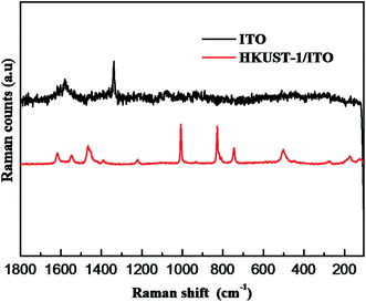
In order to further indicate the synthesis of HKUST-1, Raman spectroscopy is used to obtain structural information on HKUST-1 (Fig. 3). Comparison with ITO, the spectrum of HKUST-1 is dominated by modes associated with the organic part of the MOF framework. For example, the bands at 1610 and 1006 cm−1 are associated with ν(C![[double bond, length as m-dash]](https://www.rsc.org/images/entities/char_e001.gif) C) modes of the benzene ring; the peaks at 826 and 740 cm−1 are ascribed to out-of-plane ring (C–H) bending vibrations and to out-of-plane ring bending, respectively, while the doublet at 1550 and 1460 cm−1 is due to the νsym(C–O2) and νym(C–O2) units.13
C) modes of the benzene ring; the peaks at 826 and 740 cm−1 are ascribed to out-of-plane ring (C–H) bending vibrations and to out-of-plane ring bending, respectively, while the doublet at 1550 and 1460 cm−1 is due to the νsym(C–O2) and νym(C–O2) units.13
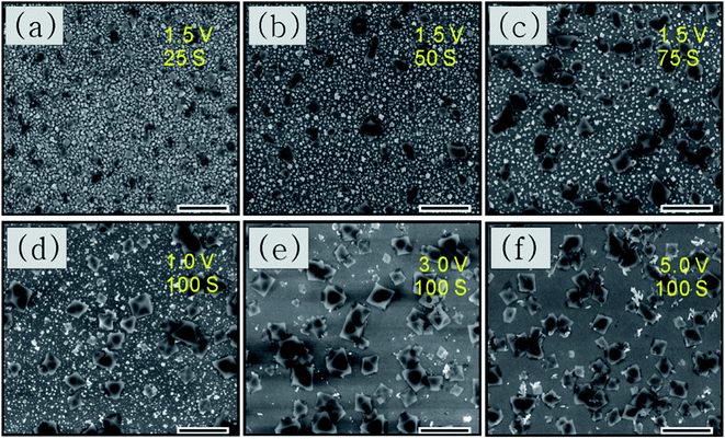
We used SEM to perform a preliminary study of the deposition time and potential used for synthesis. Fig. 4(a–c) shows the morphologies of the resultant crystals deposited with different times taken for anodic dissolution of Cu with a constant potential of 1.5 V vs. SCE. For 25 s, as shown in Fig. 4(a), very little Cu has dissolved and HKUST-1 particles sparsely cover the ITO surface. For longer anodization times such as 50 s, small HKUST-1 crystals with discernible shapes begin appearing on the ITO, increasing the distribution density of HKUST-1. After 75 s, the crystal morphology is clearly octahedral and most of the Cu film has dissolved. The potential used could also determine the final morphology of HKUST-1 on ITO; thus, it is important to study. In our method, we can control the concentration of Cu ions by monitoring the applied potential; a higher anodic potential corresponds to a higher concentration of Cu ions due to dissolution of the Cu film. Fig. 4(d–f) shows the final morphologies of samples deposited at different potentials for 100 s. As Fig. 4(d) shows, when the oxidation potential is 1 V, only a low concentration of Cu2+ is generated, and intergrowth of truncated octahedral crystals occurs. For 3 V as in Fig. 4(e), the intermediate concentration of Cu2+ leads to a well-defined octahedral HKUST-1. However, at 5 V as in Fig. 4(f), the very high concentration of Cu2+ results in more irregular crystals. Thus, formation kinetics can be tuned by adjusting the applied potential and the time of anodic dissolution of the Cu film.
4. Conclusions
We have successfully fabricated HKUST-1 on ITO using a two-step electrochemical synthesis: electro-deposition of Cu on ITO and then electro-oxidation of the Cu/ITO to HKUST-1/ITO. This method is simple, fast, mild, and environmentally friendly, and we believe that it will benefit research on electrochemical synthesis of other MOFs. More importantly, this approach allows us to coat patterned MOFs onto many other kinds of conductive substrates used in microelectronic devices.Acknowledgements
The authors are grateful for financial support from the National Science Foundation of China (21573043, 21173048, 21073038). The authors would also like to acknowledge Professor Zhao-Xiong Xie and Senior Engineer Yi-Wen Ye from Xiamen University for their help measuring the XRD spectra of HKUST-1/ITO.References
- S. L. James, Metal–organic frameworks, Chem. Soc. Rev., 2003, 32, 276–288 RSC.
- H. C. Zhou, J. R. Long and O. M. Yaghi, Introduction to metal–organic frameworks, Chem. Rev., 2012, 112, 673–674 CrossRef CAS PubMed.
- J. R. Li, J. Sculley and H. C. Zhou, Metal–organic frameworks for separations, Chem. Rev., 2012, 112, 869–932 CrossRef CAS PubMed.
- R. Senthil Kumar, S. Senthil Kumar and M. Anbu Kulandainathan, Efficient electrosynthesis of highly active Cu3(BTC)2-MOF and its catalytic application to chemical reduction, Microporous Mesoporous Mater., 2013, 168, 57–64 CrossRef CAS.
- R. Senthil Kumar, S. Senthil Kumar and M. Anbu Kulandainathan, Highly selective electrochemical reduction of carbon dioxide using Cu based metal organic framework as an electrocatalyst, Electrochem. Commun., 2012, 25, 70–73 CrossRef CAS.
- J. Mao, L. Yang, P. Yu, X. Wei and L. Mao, Electrocatalytic four-electron reduction of oxygen with copper(II)-based metal–organic frameworks, Electrochem. Commun., 2012, 19, 29–31 CrossRef CAS.
- R. Ameloot, L. Stappers, J. Fransaer, L. Alaerts, B. F. Sels and D. E. De Vos, Patterned Growth of Metal–Organic Framework Coatings by Electrochemical Synthesis, Chem. Mater., 2009, 21, 2580–2582 CrossRef CAS.
- T. R. C. Van Assche, G. Desmet, R. Ameloot, D. E. De Vos, H. Terryn and J. F. M. Denayer, Electrochemical synthesis of thin HKUST-1 layers on copper mesh, Microporous Mesoporous Mater., 2012, 158, 209–213 CrossRef CAS.
- A. Martinez Joaristi, J. Juan-Alcañiz, P. Serra-Crespo, F. Kapteijn and J. Gascon, Electrochemical Synthesis of Some Archetypical Zn2+, Cu2+, and Al3+ Metal Organic Frameworks, Cryst. Growth Des., 2012, 12, 3489–3498 CAS.
- L. E. Kreno, K. Leong, O. K. Farha, M. Allendorf, R. P. Van Duyne and J. T. Hupp, Metal–organic framework materials as chemical sensors, Chem. Rev., 2012, 112, 1105–1125 CrossRef CAS PubMed.
- S. S.-Y. Chui, S. M.-F. Lo, J. P. H. Charmant, A. G. Orpen and I. D. Williams, A Chemically Functionalizable Nanoporous Material [Cu3(TMA)2(H2O)3]n, Science, 1999, 283, 1148–1150 CrossRef CAS PubMed.
- J. Tang, J. L. Zhuang, L. Zhang, W. H. Wang and Z. W. Tian, Cu micropatterning on n-Si(111) by selective electrochemical deposition using an agarose stamp, Electrochim. Acta, 2008, 53, 5628–5631 CrossRef CAS.
- C. Prestipino, L. Regli, J. G. Vitillo, F. Bonino, A. Damin, C. Lamberti, A. Zecchina, P. L. Solari, K. O. Kongshau and S. Bordiga, Local Structure of Framework Cu(II) in HKUST-1 Metallorganic Framework Spectroscopic Characterization upon Activation and Interaction with Adsorbates, Chem. Mater., 2006, 18, 1337–1346 CrossRef CAS.
| This journal is © The Royal Society of Chemistry 2017 |


