DOI:
10.1039/C6RA26859E
(Paper)
RSC Adv., 2017,
7, 8779-8785
Electronic, optical and mechanical properties of SrSi6N8 and SrSi6N8O via first-principles
Received
15th November 2016
, Accepted 19th January 2017
First published on 27th January 2017
Abstract
The different properties of two structurally similar nitridosilicates, SrSi6N8 and SrSi6N8O, are attributed to the oxygen atom. To explore the effects of the O atom on the properties, structural, electronic, optical and mechanical properties of SrSi6N8, SrSi6N8O and O-doped SrSi6N8 have been simulated via first-principles in this work. The results indicate the Si–O–Si bond is stronger than the Si–Si bond, resulting in a more stable crystal structure of SrSi6N8O compared with SrSi6N8. The calculated bandgaps (Eg) of SrSi6N8 and SrSi6N8O are 3.10 and 3.97 eV, respectively. The lower Eg of SrSi6N8 originates from the Si–Si σ* bond, however, the Eg can be enlarged through introducing the O atom into the Si–Si bond. The optical properties illustrate that the refractive peaks are blue-shifted with O doping into the lattice of SrSi6N8. Furthermore, the elastic properties show that SrSi6N8 and SrSi6N8O are comparable to traditional mechanical ceramics such as sialons. This work not only expounds the difference between SrSi6N8 and SrSi6N8O, but also gives theoretical foundation for their potential applications as optical and mechanical materials.
1. Introduction
Nitridosilicates doped with active ions (such as Eu2+ and Ce3+) have been widely used as phosphors in phosphor-converted light emitting diodes (pc-LEDs) in consideration of their high chemical and thermal stability in combination with low thermal quenching and high conversion efficiencies.1–3 Compared to traditional phosphors such as orthosilicates (e.g. Sr2SiO4:Eu2+)4 or alkaline earth sulfides (e.g. SrCa2S4:Eu2+),5 nitridosilicates have more diversiform crystal structures owing to their more varied crosslinking patterns.6 In nitridosilicates, the N can connect up to four neighboring Si tetrahedral centers, causing a higher degree of lattice condensation to improve the chemical stability of nitride phosphors, preventing the hydrolysis reaction which often happens in phosphors with terminal or ionic O or S atoms over time.7,8
In the last few years, research into rare earth metals activating alkaline-earth-metal nitridosilicates-based phosphors has become increasingly important, such as MSi6N8 (M = Sr and Ba),9,10 MSi7N10 (M = Sr, Ba),11,12 M2Si5N8 (M = Ca, Sr and Ba),13–15 MSiN2 (M = Sr, Ba),16 and Ba5Si2N6.17 Among the available alkaline earth nitridosilicates-based phosphors, SrSi6N8 is very different from the others. For example, the oxidation states of Si are +III and +IV in SrSi6N8, and the framework contains single Si–Si bonds in N3Si–SiN3,9 as seen in Fig. 1(a). Also, SrSi6N8:Eu2+ was reported to have blue luminescent property of 450–455 nm,18,19 while most of nitridosilicates-based phosphors emitted yellow to red wavelengths. Besides, because of the structural similarity compared with MSi6N8, MSi6N8O (M = Ca and Ba) based material has also been reported to have excellent luminescent properties. Fig. 1(b) shows the crystal structure of SrSi6N8O, which can be gained by inserting one O atom into the single Si–Si bond in SrSi6N8.9 Although there is no experimental report of the preparation of pure SrSi6N8O, the compound of Sr2Si12−xAlxN16−xO2+x:Eu2+ (x ≈ 2) has been synthesized by Z Shen.20 Sr2Si12−xAlxN16−xO2+x exhibits an isotypic structure compared with SrSi6N8O, therefore the analogous silicon atoms are also bridged by oxygen atoms. Also, the photoluminescence properties of Eu activating CaSi6N8O and BaSi6N8O have been studied experimentally. The reported main photoluminescent peaks are at about 500 nm for BaSi6N8O:Eu2+,21,22 614 and 587 nm for BaSi6N8O:Eu3+,23 and 405 nm for CaSi6N8O:Eu2+.24 Furthermore, some alkaline-earth-metal nitridosilicates have been reported to have excellent mechanical properties. For instance, SrSi7N10 has a yield hardness of 16.1(5) GPa,11 and CaAlSiN3 has been considered as a relatively hard materials from first-principles simulation.25 However, even SrSi6N8 and SrSi6N8O have been investigated a lot in previous works, there is almost no paper having reported their basic characteristics such as electronic, optical and mechanical properties. In order to take full advantage of the properties of SrSi6N8 and SrSi6N8O for eventual technological applications, a better understanding of their electronic, optical and mechanical properties is required. What's more, the photoluminescence peaks of intrinsic and O-replacement defective SrSi6N8 have been reported by Wen Yeh et al. to locate at 452 and 652 nm, respectively.26 The results show that the oxygen atom has significant effect on electronic and optical properties of SrSi6N8. Actually, nitrogen-rich sialon materials, with partial substitutions of Si by Al and N by O, have attracted great interest owing to their excellent optical and mechanical performance.3 The ratio of O![[thin space (1/6-em)]](https://www.rsc.org/images/entities/char_2009.gif) :
:![[thin space (1/6-em)]](https://www.rsc.org/images/entities/char_2009.gif) N has the significant effect on the properties of sialon materials. So introducing the O atom into the lattice of SrSi6N8 may generate positive effects on electronic, optical and mechanical properties. Considering that the big difference between SrSi6N8 and SrSi6N8O is the O atom, investigating the effect of O atom on SrSi6N8 may also give some ideas to understand the difference in their properties.
N has the significant effect on the properties of sialon materials. So introducing the O atom into the lattice of SrSi6N8 may generate positive effects on electronic, optical and mechanical properties. Considering that the big difference between SrSi6N8 and SrSi6N8O is the O atom, investigating the effect of O atom on SrSi6N8 may also give some ideas to understand the difference in their properties.
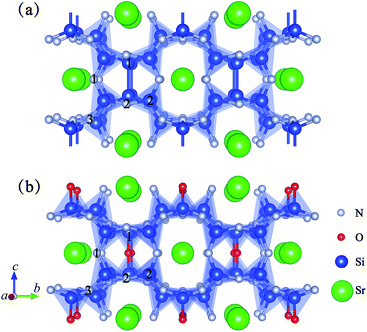 |
| | Fig. 1 Projective representation of 2 × 2 × 1 supercells of (a) SrSi6N8 and (b) SrSi6N8O. | |
Herein, in this work, first-principles calculations27–29 have been used to investigate the electronic, optical and mechanical properties of SrSi6N8, SrSi6N8O, and O-doped SrSi6N8. On the one hand, this work has given the comparison and explanation of the difference between SrSi6N8 and SrSi6N8O in electronic, optical and mechanical properties. On the other hand, the effects of O atom on SrSi6N8 have also been investigated through introducing O atoms to replace different N atoms and to insert into the single Si–Si bond. This work not only explains the difference between SrSi6N8 and SrSi6N8O, but also gives the theoretical foundation for their potential applications.
2. Theoretical and computational methods
Fig. 1 shows the crystal structures of 2 × 2 × 1 SrSi6N8 and 2 × 2 × 1 SrSi6N8O supercells. As seen in Fig. 1(a), there are two types of connectivity models of N atoms, which are bonded with two Si atoms (marked as N[2]) and three Si atoms (marked as N[3]). And the spatial locations of Si–N[3]–Si bonds are vertical and with a certain angle to the b axis.9 So, we marked the N[2] as N1, the two N atoms in the different Si–N[3]–Si bonds as N2 and N3, the Si atoms in the Si–Si bonds as Si1, and the other Si atoms as Si2, as seen in Fig. 1(a). Herein, four types of O-doped 2 × 2 × 1 SrSi6N8 supercells were considered in our work, which were Oi substituting to Ni (i = 1, 2 and 3) and O4 inserting into the Si–Si bond, and marked as Oi–SrSi6N8 (i = 1, 2, 3 and 4), respectively.
All first principle calculations were performed using Cambridge Serial Total Energy Package (CASTEP) code.29 The electronic exchange–correlation function was Perdew Burke Ernzerhof (PBE) of generalized gradient approximation (GGA).30 Ultrasoft pseudopotentials were used with 5s2 5p0, 3s2 3p2, 2s2 2p3 and 2s2 2p4 as the valence-electron configurations for Sr, Si, N and O atoms, respectively, to describe the interactions between ions and electrons.31 With convergence testing, the plane-wave cutoff energy of 400 eV and k-point meshes of 3 × 2 × 3 were used to ensure the accuracy and efficiency of calculations. The threshold for self-consistent field iterations was 5.0 × 10⁻⁷ eV per atom. The convergence tolerance parameters of optimized calculation were the energy of 1.0 × 10⁻⁵ eV per atom, the maximum force of 0.03 eV Å−1, the maximum inner stress of 0.05 GPa and the maximum displacement of 1.0 × 10⁻⁴ nm. After finishing geometry optimizations, electronic, optical and mechanical properties of all models were calculated. The lattice stabilities of all the optimized structures were evaluated by the phonon dispersions, where the imaginary frequency was the sign of lattice instability.32,33
Considering no experimental report of the preparation of pure SrSi6N8O, we used the acid–base idea as mentioned by M. Mikami34 to assume the solid-state reaction for production of SrSi6N8O. The binary oxide is generally considered as acid while binary nitride as base. So the reaction for production of SrSi6N8O should be defined as following:
| | |
SrO + 2Si3N4 → SrSi6N8O
| (1) |
The formation energy (Eform) of reaction [1] was calculated as following equation:
| | |
Eform = ESrSi6N8O − ESrO − 2ESi3N4
| (1) |
where the
ESrSi6N8O,
ESrO and
ESi3N4 were the total energies of SrSi
6N
8O, SrO and α-Si
3N
4, respectively. A negative value of formation energy indicates the reaction is exothermic and the production is stable.
The binding energy (Eb) can be used to investigate the relative stability of the model. The value of binding energies of all models were calculated by the following formula:35
| |
 | (2) |
where the
Etot was the total energy of the considered model, and the chemical potentials of Si, N and O were defined as
μSi =
μbulk−Si,
μN =
μN2/2 and
μO =
μO2/2, respectively.
36,37 The coefficients
nSi,
nN and
nO were the numbers of the Si, N and O atoms in each model. For O-doped SrSi
6N
8 models, the values of bonding energies were used to predict the preferential position for O doping in the lattice of SrSi
6N
8.
Understanding elastic properties of nitridosilicates is very important for their application and improvement. For orthorhombic crystals, it is known that the mechanical stability requires elastic constants satisfying the following conditions:38,39
| c11 + c22 + c33 + 2c12 + 2c13 + 2c23 > 0, |
The mechanical constants: bulk modulus (B), shear modulus (G), Young's modulus (E), and Poisson's ratio (ν) have been calculated using the following equations:38,39
| | |
B = (1/9)(c11 + c22 + c33 + 2c12 + 2c13 + 2c23)
| (4) |
| | |
G = (1/15)[(c11 + c22 + c33 + 3(c44 + c55 + c66) − c12 − c13 − c23)]
| (5) |
| | |
ν = (1/2)(3B − 2G)/(3B + G)
| (7) |
3. Results and discussion
3.1 Geometry optimization results
Table 1 lists the calculated lattice parameters, average bond lengths and binding energies of all models. The lattice parameters of 2 × 2 × 1 SrSi6N8 and 2 × 2 × 1 SrSi6N8O supercells are well agreement with previous results.9,24 There is no big change in the lattice parameters after O doping into SrSi6N8. The slight volume expansions come from the changes of local bond lengths. The average bond lengths of Si–O[2] and Si–O[3] are larger than the Si–N[2] and Si–N[3] in Oi–SrSi6N8 (i = 1, 2 and 3), while the average bond length of Si–O[2] is smaller than the Si–N[2] in O4–SrSi6N8. The results indicate that different coordination environments of O atom has different effects on the Si–O bond lengths. The Eform of pure SrSi6N8O calculated by eqn (1) is −0.37 eV, which indicates that the reaction [1] is somewhat exothermic and SrSi6N8O is stable. The lower value of Eb indicates the more stable degree of the model. The Eb (−1.71 eV) of SrSi6N8O means that it has the more stable crystal structure and can be easier to synthesis compared with SrSi6N8 (−1.40 eV). These phenomenon is corresponding to the fact that SrSi6N8 is a kind of reduced nitridosilicate and must be synthesized under the condition of extreme lack of oxygen.9 The Eb of O4–SrSi6N8 (−1.45 eV) is the lowest one among all O-doped SrSi6N8 models, meaning that O atom prefers to insert into the single Si–Si bond to stabilize the crystal structure of SrSi6N8.
Table 1 Optimized lattice parameters, bond lengths and binding energies of all models
| Models |
Lattice parameters (Å) |
Volume (Å3) |
Average bond length (Å) |
Eb (eV) |
| a |
b |
c |
Si–N[2] |
Si–N[3] |
Si–Si |
Si–O[2] |
Si–O[3] |
| Ref. 9. Ref. 19. |
| SrSi6N8 |
9.664 |
15.854 |
9.331 |
1429.56 |
1.679 |
1.755 |
2.379 |
|
|
−1.40 |
| SrSi6N8a |
4.801 |
7.855 |
9.260 |
349.21 |
|
|
2.352 |
|
|
|
| SrSi6N8b |
4.803 |
7.836 |
9.261 |
350.93 |
|
|
|
|
|
|
| O1–SrSi6N8 |
9.682 |
15.897 |
9.302 |
1431.80 |
1.680 |
1.757 |
2.367 |
1.688 |
|
−1.43 |
| O2–SrSi6N8 |
9.679 |
15.869 |
9.331 |
1433.13 |
1.678 |
1.757 |
2.370 |
|
1.850 |
−1.42 |
| O3–SrSi6N8 |
9.670 |
15.890 |
9.320 |
1432.10 |
1.679 |
1.757 |
2.370 |
|
1.811 |
−1.42 |
| O4–SrSi6N8 |
9.673 |
15.939 |
9.400 |
1449.29 |
1.681 |
1.756 |
2.406 |
1.589 |
|
−1.45 |
| SrSi6N8O |
9.722 |
16.400 |
9.706 |
1547.62 |
1.683 |
1.752 |
|
1.620 |
|
−1.71 |
| SrSi6N8Oa |
4.865 |
8.206 |
9.721 |
|
|
|
|
|
|
|
Furthermore, phonon dispersions of all optimized models have been calculated to evaluate the structural stability, as seen in Fig. 2. The results shows that there is no imaginary frequency of pure SrSi6N8 and SrSi6N8O, which means that SrSi6N8 and SrSi6N8O are structurally stable. The lowest frequencies of Oi–SrSi6N8 (i = 1, 2, 3 and 4) are −0.20, −0.81, −0.53 and −0.05 THz, respectively. According to the previous works, the small negative frequencies of O1–SrSi6N8 and O4–SrSi6N8 could be ignored because the small negative frequencies may be caused by the relatively smaller supercells and lower computational accuracies.32,33 However, the calculation of phonon dispersion is time consuming with a bigger supercell and higher computational accuracy. So we think it is reasonable to consider O1–SrSi6N8 and O4–SrSi6N8 as structurally stable models based on the calculated phonon dispersions. While, the structures of O2–SrSi6N8 and O3–SrSi6N8 are metastable or unstable according to their obvious imaginary frequencies as seen in Fig. 2(d) and (e). The results of phonon dispersions are well agreement with the results of bonding energies (Eb), which means that the structures of O1–SrSi6N8 and O4–SrSi6N8 are more stable than O2–SrSi6N8 and O3–SrSi6N8.
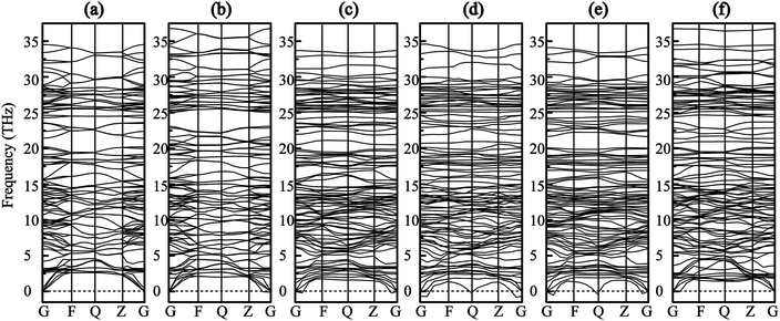 |
| | Fig. 2 Phonon dispersion curves (a) SrSi6N8, (b) SrSi6N8O, (c) O1–SrSi6N8, (d) O2–SrSi6N8, (e) O3–SrSi6N8 and (f) O4–SrSi6N8. | |
3.2 Electronic properties
Fig. 3 shows the band structures and partial density of states (PDOS) of SrSi6N8 and SrSi6N8O. The calculated bandgaps (Eg) of SrSi6N8 and SrSi6N8O are 3.10 and 3.97 eV, respectively. Although, there is no experimentally reported the Eg of SrSi6N8 or SrSi6N8O, our GGA calculated Eg are expected to be smaller than experimental values since the underestimation of GGA calculation.39 While the effects of oxygen on electronic properties of SrSi6N8 can be expounded through the relative changes. The top of valence bands of SrSi6N8 and SrSi6N8O are occupied by N 2p states. Differing in band structures from the other alkaline-earth-metal nitridosilicates,6 there are some energy levels below the conduction bands of SrSi6N8, which are mainly constituted of Si 3p states as seen from the PDOS. Furthermore, the 3p states of Si1 contribute the more parts of the bottom of conduction bands compared to Si2, which indicates that the energy levels below the conduction bands are attributed to the single Si–Si bond. The previous works reported that Si–Si bond forms an empty σ* state under the bottom of conduction bands in some nitrides.40,41 Therefore, the Si–Si σ* state is the main reason for the lower bandgap of SrSi6N8 compared to SrSi6N8O.
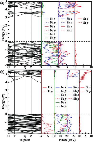 |
| | Fig. 3 Band structures and partial density of states (PDOS) of (a) SrSi6N8 and (b) SrSi6N8O. | |
Furthermore, the electron density distribution (EDD) plots are calculated to investigate the difference between Si–Si and Si–O–Si bonds. Fig. 4(a) and (b) illustrate the partial atom distributions and corresponding EDD plots on the (010) plane of SrSi6N8 and SrSi6N8O, respectively. We can find that there is a small amount of electron density distributing in the center of Si–Si bond in SrSi6N8, while a high density of electron gathers on the O atoms in SrSi6N8O. The stronger electronic interaction of Si–O–Si bond gives the more stable crystal structure for SrSi6N8O, which is consistent with results of the calculated Eb. Besides, the electron densities of O atoms are obviously higher than that of N atoms in SrSi6N8O, which is attributed to the stronger electronegativity of O atom.
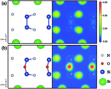 |
| | Fig. 4 Partial atom distributions and corresponding electron density distribution plots of (a) SrSi6N8 and (b) SrSi6N8O on the (010) plane. | |
The calculated band structures and PDOS of the O atoms and its adjacent Si atoms for all O-doped SrSi6N8 models are plotted in Fig. 5. The calculated bandgaps (Eg) of Oi–SrSi6N8 (i = 1, 2, 3 and 4) are 3.17, 2.84, 3.09 and 3.33 eV, respectively. For O1–SrSi6N8, as seen in Fig. 5(a), the band structure of O1–SrSi6N8 is very close to that of undoped SrSi6N8, which indicates that the O[2] has the similar properties of N[2]. As seen in Fig. 5(b) and (c), the reason of the Eg decreasing for O2–SrSi6N8 and O3–SrSi6N8 is that the hybrid Si–O bonds generate energy levels under the conduction bands. For O4–SrSi6N8, the distribution of O 2p states are very similar to that of SrSi6N8O, showing that the O4 atom has the same character to the O atoms in SrSi6N8O. The Eg of O4–SrSi6N8 is larger than that of SrSi6N8, which indicates that inserting O atom into the single Si–Si bond to decrease the concentration of Si–Si bonds can increase the Eg.
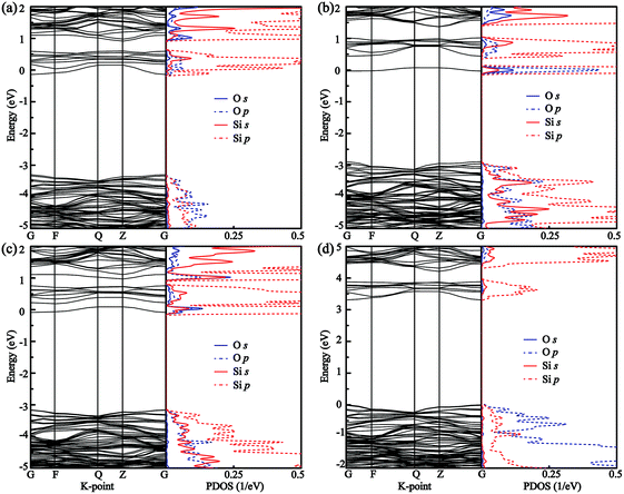 |
| | Fig. 5 Band structures and PDOS of (a) O1–SrSi6N8, (b) O2–SrSi6N8, (c) O3–SrSi6N8, and (d) O4–SrSi6N8. | |
3.3 Optical properties
The absorption coefficient is one of key parameters to evaluate the performance for phosphors. The absorption spectra can be described in terms of time-dependent perturbations of the ground-state electronic states, which has always been investigated combined the electron transition between valance bonds and conduction bonds.42 Fig. 6 shows the calculated absorption spectra of all models. The absorption peak for undoped SrSi6N8 is located at about 3.0–15.0 eV, which are corresponding to the electron transitions from N 2p states in the valence bands to Si 3p and Sr 5s states in the conduction bands as shown from PDOS in Fig. 3(a). The absorption edge of SrSi6N8O starts at 3.9 eV, with a large blue shift compared to that of SrSi6N8 at 2.9 eV. The positions of the main absorption peaks for Oi–SrSi6N8 (i = 1, 2, 3 and 4) are almost the same as SrSi6N8, while the absorption intensities become lower. Besides, as show in the enlarged view in Fig. 5, the weak peaks located around 0–3.0 eV of the O2–SrSi6N8 and O3–SrSi6N8 derive from the electron transitions between Si–O hybrid states under the bottom of conduction bands and conduction bands, as shown in Fig. 5(b) and (c).
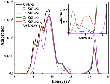 |
| | Fig. 6 Calculated absorption spectra of SrSi6N8, SrSi6N8O and O-doped SrSi6N8 models. | |
Fig. 7 shows the refractive spectra of SrSi6N8, SrSi6N8O and O-doped SrSi6N8 models. Although, there is no experimentally reported refractive index (n) of SrSi6N8 or SrSi6N8O, the static refractive indexes (n0) of SrSi6N8 (1.67) and SrSi6N8O (1.39) are expected to be lower than the experimental value due to the underestimated calculation of GGA-PEB.39 Nevertheless, the relative changes can reflect the effects of O atoms on SrSi6N8. The calculated static refractive indexes of Oi–SrSi6N8 (i = 1, 2 and 3 and 4) are 1.65, 2.08, 1.69 and 1.56, respectively, which are well corresponding to Moss rule that the static refractive index is inversely proportional to the Eg.43 Except for the static refractive indexes, the main peaks of refractive indexes of all O-doped SrSi6N8 models are lower than that of SrSi6N8. Furthermore, compared with SrSi6N8, the locations of main peaks for SrSi6N8O are significantly blue-shift. The results of optical properties show that different doping sites of O atoms in SrSi6N8 have different effects on its basic absorption and refractive spectra.
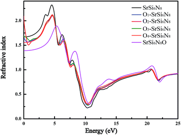 |
| | Fig. 7 Calculated refractive spectra of SrSi6N8, SrSi6N8O and O-doped SrSi6N8 models. | |
3.4 Mechanical properties
The optimized structures of all models have been applied to calculate the elastic tensors which consist of nine independent components, as tabulated in Table 2. It can be seen that the relationships of elastic constants satisfy the conditions as shown in eqn (3), which indicates that SrSi6N8, SrSi6N8O and O-doped SrSi6N8 are mechanically stable.
Table 2 Calculated elastic tensor Cij (GPa) for all models
| Models |
C11 |
C22 |
C33 |
C44 |
C55 |
C66 |
C12 |
C13 |
C23 |
| SrSi6N8 |
380.08 |
308.27 |
341.91 |
94.79 |
81.51 |
131.64 |
91.21 |
84.21 |
101.08 |
| O1–SrSi6N8 |
272.6 |
288.96 |
349.77 |
76.14 |
120.84 |
85.98 |
88.23 |
68.13 |
65.22 |
| O2–SrSi6N8 |
326.66 |
320.01 |
376.75 |
89.42 |
148.04 |
96.83 |
102.69 |
95.72 |
77.35 |
| O3–SrSi6N8 |
308.17 |
332.72 |
378.19 |
83.16 |
133.37 |
96.20 |
100.24 |
94.78 |
79.93 |
| O4–SrSi6N8 |
299.77 |
320.38 |
371.85 |
81.32 |
135.48 |
96.61 |
99.14 |
96.71 |
77.35 |
| SrSi6N8O |
324.25 |
377.85 |
374.25 |
92.30 |
67.54 |
142.86 |
85.77 |
71.16 |
119.8 |
Furthermore, the mechanical constants: bulk modulus (B), shear modulus (G), Young's modulus (E), and Poisson's ratio (ν) for all models are listed in Table 3. The mechanical constants: B, G and E of SrSi6N8O are larger than that of SrSi6N8, which mainly attributes to the more stable Si–O–Si bond than Si–Si bond. Though introducing O atom produces a certain degree of lattice distortion in SrSi6N8, there is no obvious deterioration on mechanical properties of O-doped SrSi6N8 compared to undoped SrSi6N8, even some mechanical constants are improved. Besides, with the comparison of traditionally mechanical ceramics such as sialons (B = 170–240 GPa, G = 118.84 GPa and E = 197–283 GPa),44,45 the mechanical properties of all models considered in this work indicate that they have the application prospect for mechanical ceramics.
Table 3 Calculated bulk modulus B (GPa), shear modulus G (GPa), Young's modulus E (GPa) and Poisson's ratio ν for all models
| Models |
B |
G |
E |
ν |
| SrSi6N8 |
175.92 |
111.84 |
276.85 |
0.24 |
| O1–SrSi6N8 |
150.5 |
102.58 |
250.77 |
0.22 |
| O2–SrSi6N8 |
174.99 |
116.7 |
286.43 |
0.23 |
| O3–SrSi6N8 |
174.33 |
112.15 |
277.04 |
0.24 |
| O4–SrSi6N8 |
170.93 |
100.6 |
252.30 |
0.25 |
| SrSi6N8O |
181.09 |
113.85 |
282.37 |
0.24 |
4. Conclusions
In this work, first-principles simulation has been performed to investigate the structural, electronic, optical and mechanical properties of SrSi6N8, SrSi6N8O and O-doped SrSi6N8. Firstly, this work has given the comparison and explanation of the difference between the two structurally similar nitridosilicates SrSi6N8 and SrSi6N8O. The results show that SrSi6N8O is more stable than SrSi6N8, and the Eg of SrSi6N8O is larger than that of SrSi6N8. The key factor of the difference between SrSi6N8 and SrSi6N8O is the O atom. Namely, the Si–O–Si bond is stronger than the single Si–Si bond, which contributes to the more stable crystal structure of SrSi6N8O. And the Si–Si σ* states under the conduction bonds are the main reason for the smaller Eg of SrSi6N8 compared to SrSi6N8O.
Secondly, the effects of O on electronic, optical and mechanical properties of SrSi6N8 have been investigated systematically. The crystal structure of SrSi6N8 can be stabilized with doping O into the lattice and the most preferential doping position of O is insertion between the single Si–Si bonds. And introducing O into the Si–Si bond can significantly increase the Eg of SrSi6N8. The static refractive indexes become larger for O substituting to N models while become smaller for the O insert into the Si–Si bond. Besides, the calculated mechanical constants are comparable to traditionally mechanical ceramics such as sialons, which indicates SrSi6N8, SrSi6N8O and O-doped SrSi6N8 have potential applications as mechanical materials. This work is helpful to understand the difference between SrSi6N8 and SrSi6N8O, and opens up their possibility of new application.
Acknowledgements
The project is supported by the National Natural Science Foundation of China (51202171, 51472188 and 51521001), the Specialized Research Fund for the Doctoral Program of Higher Education of China (20120143120004), the “111” project (B13035), the Fundamental Research Funds for the Central Universities (WUT: 2016-YB-003) and the China Scholarship Council (CSC).
Notes and references
- R. J. Xie and N. Hirosaki, Sci. Technol. Adv. Mater., 2007, 8, 588–600 CrossRef CAS.
- S. Ye, F. Xiao, Y. X. Pan, Y. Y. Ma and Q. Y. Zhang, Mater. Sci. Eng., R, 2010, 71, 1–34 CrossRef.
- M. Zeuner, S. Pagano and W. Schnick, Angew. Chem., Int. Ed., 2011, 50, 7754–7775 CrossRef CAS PubMed.
- N. Lakshminarasimhan and U. V. Varadaraju, J. Electrochem. Soc., 2005, 152, H152–H156 CrossRef CAS.
- S. M. Jacobsen, J. Soc. Inf. Disp., 1996, 4, 331–335 CrossRef.
- R. J. Xie, Y. Q. Li, N. Hirosaki and H. Yamamoto, Nitride Phosphors and Solid-State Lighting, Taylor & Francis, 2011 Search PubMed.
- P. Schmidt, A. Tuecks, J. Meyer, H. Bechtel, D. Wiechert, R. Mueller-Mach, G. Mueller and W. Schnick, 7th Inter. Conf. Solid State Lighting, 2007 Search PubMed.
- H. Huppertz and W. Schnick, Z. Anorg. Allg. Chem., 1997, 623, 212 CrossRef CAS.
- F. Stadler, O. Oeckler, J. Senker, H. A. Höppe, P. Kroll and W. Schnick, Angew. Chem., Int. Ed., 2005, 117, 573–576 CrossRef.
- F. Stadler and W. Schnick, Z. Anorg. Allg. Chem., 2007, 633, 589–592 CrossRef CAS.
- G. Pilet, H. A. Höppe, W. Schnick and S. Esmaeilzadeh, Solid State Sci., 2005, 7, 391 CrossRef CAS.
- Y. Q. Li, A. C. A. Delsing, R. Metslaara, G. de Witha and H. T. Hintzen, J. Alloys Compd., 2009, 487, 28 CrossRef CAS.
- M. Zeuner, F. Hintze and W. Schnick, Chem. Mater., 2009, 21, 336 CrossRef CAS.
- K. S. Sohn, B. Lee, R. J. Xie and N. Hirosaki, Opt. Lett., 2009, 34, 3427 CrossRef CAS PubMed.
- H. Nersisyan, H. I. Won and C. W. Won, Chem. Commun., 2011, 47, 11897 RSC.
- C. J. Duan, X. J. Wang, W. M. Otten, A. C. A. Delsing, J. T. Zhao and H. T. Hintzen, Chem. Mater., 2008, 20, 1597 CrossRef CAS.
- H. Yamane and F. J. DiSalvo, J. Alloys Compd., 1996, 240, 33–36 CrossRef CAS.
- K. Shioi, N. Hirosaki, R. J. Xie, T. Takeda and Y. Li, J. Mater. Sci., 2008, 43, 5659–5661 CrossRef CAS.
- S. M. Wu, H. E. Hung, C. H. Hsieh, Y. C. Lin, L. C. Wang, Y. T. Tsai, C. C. Lin and R. S. Liu, J. Am. Ceram. Soc., 2015, 98, 2662–2669 CrossRef CAS.
- Z. Shen, J. Grins, S. Esmaeilzadeh and H. Ehrenberg, J. Mater. Chem., 1999, 9, 1019–1022 RSC.
- N. Karkada, D. Porob, N. K. Prasanth and A. Setlur, ECS Trans., 2009, 16, 41–50 CAS.
- R. J. Xie, N. Hirosaki, Y. Li and T. Takeda, J. Lumin., 2010, 130, 266–269 CrossRef CAS.
- S. A. Fartode, B. S. Reddy, V. Nayar and S. J. Dhoble, Ferroelectr., Lett. Sect., 2016, 43, 34–51 CrossRef CAS.
- Y. H. Song, T. Y. Choi, Y. Y. Luo, K. Senthil and D. H. Yoon, Opt. Mater., 2011, 33, 989–991 CrossRef CAS.
- Z. Wang, B. Shen, F. Dong, S. Wang and W. S. Su, Phys. Chem. Chem. Phys., 2015, 17, 15065–15070 RSC.
- C. W. Yeh, Y. P. Liu, Z. R. Xiao, Y. K. Wang, S. F. Hu and R. S. Liu, J. Mater. Chem., 2012, 22, 5828–5834 RSC.
- G. Kresse and D. Joubert, Phys. Rev. B: Condens. Matter Mater. Phys., 1999, 59, 1758 CrossRef CAS.
- Q. Peng, X. J. Chen, S. Liu and S. De, RSC Adv., 2013, 3, 7083–7092 RSC.
- M. D. Segall, P. J. Lindan, M. A. Probert, C. J. Pickard, P. J. Hasnip, S. J. Clark and M. C. Payne, J. Phys.: Condens. Matter, 2002, 14, 2717 CrossRef CAS.
- J. P. Perdew, K. Burke and M. Ernzerhof, Phys. Rev. Lett., 1996, 77, 3865 CrossRef CAS PubMed.
- M. Marlo and V. Milman, Phys. Rev. B: Condens. Matter Mater. Phys., 2000, 62, 2899 CrossRef CAS.
- L. Zhu, L. Li, T. Cheng and D. Xu, J. Mater. Chem. A, 2015, 3, 5449–5456 CAS.
- S. S. Bhat, U. V. Waghmare and U. Ramamurty, Cryst. Growth Des., 2014, 14, 3131–3141 CAS.
- M. Mikami, ECS J. Solid State Sci. Technol., 2013, 2, R3048–R3058 CrossRef CAS.
- S. Yang, D. Li, T. Zhang, Z. Tao and J. Chen, J. Phys. Chem. C, 2011, 116, 1307–1312 Search PubMed.
- F. Oba, K. Tatsumi, I. Tanaka and H. Adachi, J. Am. Ceram. Soc., 2002, 85, 97–100 CrossRef CAS.
- K. Yang, Y. Dai and B. Huang, J. Phys. Chem. C, 2007, 111, 12086–12090 CAS.
- Z. Wu, X. Hao, X. Liu and J. Meng, Phys. Rev. B: Condens. Matter Mater. Phys., 2007, 75, 054115 CrossRef.
- B. Tu, H. Wang, X. Liu, W. Wang and Z. Fu, J. Am. Ceram. Soc., 2014, 97, 2996–3003 CrossRef CAS.
- L. E. Hintzsche, C. M. Fang, M. Marsman, G. Jordan, M. W. P. E. Lamers, A. W. Weeber and G. Kresse, Phys. Rev. B: Condens. Matter Mater. Phys., 2013, 88, 155204 CrossRef.
- Z. Huang, F. Chen, Q. Shen and L. Zhang, RSC Adv., 2016, 6, 7568–7574 RSC.
- R. Asahi, Y. Taga, W. Mannstadt and A. J. Freeman, Phys. Rev. B: Condens. Matter Mater. Phys., 2000, 61, 7459 CrossRef CAS.
- T. S. Moss, Phys. Status Solidi B, 1985, 131, 415–427 CrossRef CAS.
- J. Hafner, Z. Lenčéš and P. Šajgalík, J. Am. Ceram. Soc., 2003, 86, 1162–1167 CrossRef.
- L. Benco, J. Hafner, Z. Lences and P. Sajgalik, J. Eur. Ceram. Soc., 2008, 28, 995–1002 CrossRef CAS.
|
| This journal is © The Royal Society of Chemistry 2017 |
Click here to see how this site uses Cookies. View our privacy policy here.  Open Access Article
 *,
Jianwen Zhang,
Qiang Shen and
Lianmeng Zhang
![[thin space (1/6-em)]](https://www.rsc.org/images/entities/char_2009.gif) :
:![[thin space (1/6-em)]](https://www.rsc.org/images/entities/char_2009.gif) N has the significant effect on the properties of sialon materials. So introducing the O atom into the lattice of SrSi6N8 may generate positive effects on electronic, optical and mechanical properties. Considering that the big difference between SrSi6N8 and SrSi6N8O is the O atom, investigating the effect of O atom on SrSi6N8 may also give some ideas to understand the difference in their properties.
N has the significant effect on the properties of sialon materials. So introducing the O atom into the lattice of SrSi6N8 may generate positive effects on electronic, optical and mechanical properties. Considering that the big difference between SrSi6N8 and SrSi6N8O is the O atom, investigating the effect of O atom on SrSi6N8 may also give some ideas to understand the difference in their properties.


