 Open Access Article
N2O-emission-free exhaust remediation by Rh-NbOx nanocomposites developed from Rh3Nb alloy precursor†
Tsubasa Imaiab,
Shigenori Uedac,
Satoshi Nagaod,
Hirohito Hiratad,
Koolath Ramakrishnan Deepthie and
Hideki Abe *a
*a
aNational Institute for Materials Science, 1-1 Namiki, Tsukuba, Ibaraki 305-0044, Japan
bGraduate School of Science and Technology, Saitama University, 255 Shimo-Okubo, Saitama 338-8570, Japan
cSynchrotron X-ray Station at SPring-8, National Institute for Materials Science, 1-1-1 Kouto, Sayo, Hyogo 679-5148, Japan
dToyota Motor Corporation, Mishuku 1200, Susono, Shizuoka 410-1107, Japan
eCrystal Growth Centre, Anna University, Chennai, Tamil Nadu 600-025, India
First published on 1st February 2017
Abstract
Metal-oxide nanocomposites comprising rhodium (Rh) nanoparticles (<50 nm) and oxygen-deficient niobium oxides (NbOx: x < 5/2) were developed from Rh3Nb alloy precursors. The Rh-NbOx nanocomposite exhibited enhanced activity toward the catalytic remediation of nitrogen oxide (NO) in the presence of carbon monoxide (CO) without emissions of nitrous oxide (N2O) due to the promoted dissociation of NO admolecules at the Rh/NbOx interface.
Green-house gases, such as carbon dioxide (CO2), are becoming a serious hazard for the world's environment.1 In particular, nitrous oxide (N2O) is a universal issue because of its ability to absorb infrared light and is contributes 200 fold more than CO2 to global warming.2 Currently, 1.5% of atmospheric N2O is released as part of nitrogen oxides (NOx: N2O, NO, N2O5 and NO2) contained in automobile exhaust.3 The NOx are remediated to environmentally benign nitrogen (N2) through redox reactions with carbon monoxide (CO) that is produced by the incomplete combustion of fuels (NOx remediation).4 Nanoparticles of precious-group metals (PGM), particularly rhodium (Rh), are widely used as the catalyst for the NOx remediation.5 However, the current Rh catalysts preferentially promote the partial reduction of NO to N2O (i.e., NO + 1/2CO = 1/2N2O + 1/2CO2) instead of the desired NOx remediation, when applied to the low-temperature exhaust (<350 °C) from hybrid engines or two-stroke engines of motorcycles.6 In order to meet the demands for hybrid cars and motorcycles in the advanced and emerging countries, respectively, it is of growing importance to develop high-performance NOx remediation catalysts for the low-temperature exhaust without N2O emissions.7
It is acknowledged that Rh nanoparticles exhibit enhanced performance for either the catalytic decomposition of N2O (i.e., N2O = N2 + 1/2O2) or the low-temperature NOx remediation, when finely dispersed and immobilized on oxide-based supporting materials (supported Rh catalysts).8 Al6Si2O13 (Mullite)-supported Rh nanoparticles efficiently decomposed N2O at 350 °C or higher temperatures.9 Supporting materials comprising cerium-doped Al2O3 realized the N2O decomposition even at 250 °C.10 It was also demonstrated that the Rh nanoparticles supported on cerium-zirconium oxides ((Ce1−xZrx)Oy; y < 2) remediated the NOx at 250 °C or higher temperatures. Rh nanoparticles supported on aluminium phosphate (AlPO4) showed an improved low-temperature activity toward the NOx remediation.10 However, none of these Rh catalysts has achieved the desired low-temperature NOx remediation without N2O emission.
Herein, we report that the N2O emission-free, low-temperature NOx remediation can be realized by a nanocomposite of Rh metal and niobium oxide (i.e. Rh@NbOx) that was developed from a Rh–Nb alloy precursor (i.e. Rh3Nb) through controlled annealing in a gas mixture comprising NO and CO. Powder X-ray diffraction (pXRD), hard X-ray photoemission spectroscopy (HAXPES) and transmission-electron microscopy (TEM) have demonstrated that Rh@NbOx consisted of interconnected Rh nanoparticles (particle size < 50 nm) that were further incorporated in a matrix of oxygen-deficient niobium oxide (NbOx; x < 2.5). In situ X-ray photoemission spectroscopy (in situ XPS) has shown that the NbOx matrix can dissociate NOad at room temperature through the formation of N–Nb bonds at the Rh/NbOx interface. As a result of the promoted NOad dissociation, the Rh@NbOx efficiently catalysed the remediation of NO to N2 (NO + CO = 1/2 N2 + CO2) without N2O emission at low temperatures.
Pure-phased Rh3Nb ingots were first synthesized using arc-melting elemental metals in pure Ar atmosphere. The Rh3Nb ingot was then powdered to an average particle size of 50 μm. The obtained Rh3Nb powder was exposed to a He-balanced stream of NO/CO gas mixture at elevated temperatures up to 600 °C (NO![[thin space (1/6-em)]](https://www.rsc.org/images/entities/char_2009.gif) :
:![[thin space (1/6-em)]](https://www.rsc.org/images/entities/char_2009.gif) CO
CO![[thin space (1/6-em)]](https://www.rsc.org/images/entities/char_2009.gif) :
:![[thin space (1/6-em)]](https://www.rsc.org/images/entities/char_2009.gif) He = 1
He = 1![[thin space (1/6-em)]](https://www.rsc.org/images/entities/char_2009.gif) :
:![[thin space (1/6-em)]](https://www.rsc.org/images/entities/char_2009.gif) 1
1![[thin space (1/6-em)]](https://www.rsc.org/images/entities/char_2009.gif) :
:![[thin space (1/6-em)]](https://www.rsc.org/images/entities/char_2009.gif) 98 in volume) to convert the Rh3Nb precursor to the desired Rh@NbOx nanocomposite (see ESI for details†).
98 in volume) to convert the Rh3Nb precursor to the desired Rh@NbOx nanocomposite (see ESI for details†).
Fig. 1 shows the powder X-ray diffraction (pXRD) profiles for the Rh3Nb precursor and the Rh@NbOx nanocomposite. The pXRD peaks for the Rh3Nb precursor were located at 40.43, 47.02, 68.74, 82.86 and 87.44 degrees, which corresponded to the 111-, 200-, 220-, 311- and 322 reflections of the cubic Au3Cu structure (Pm![[3 with combining macron]](https://www.rsc.org/images/entities/char_0033_0304.gif) m, a = 0.3865 nm), respectively.11 After the exposure to the NO/CO gas mixture, the pXRD peaks shifted toward higher diffraction angles as a result of phase separation of the uniform alloy into the nanocomposite consisting of Rh and NbOx. The major reflections from the Rh@NbOx were observed at 40.92, 47.62, 69.98, 84.19 and 88.93 degrees, corresponding to the 111-, 200-, 220-, 311- and 322 reflections of the face-center cubic (FCC) structure of Rh metal (Fm
m, a = 0.3865 nm), respectively.11 After the exposure to the NO/CO gas mixture, the pXRD peaks shifted toward higher diffraction angles as a result of phase separation of the uniform alloy into the nanocomposite consisting of Rh and NbOx. The major reflections from the Rh@NbOx were observed at 40.92, 47.62, 69.98, 84.19 and 88.93 degrees, corresponding to the 111-, 200-, 220-, 311- and 322 reflections of the face-center cubic (FCC) structure of Rh metal (Fm![[3 with combining macron]](https://www.rsc.org/images/entities/char_0033_0304.gif) m, a = 0.3804 nm).12 In addition to the intense reflections from the Rh phase, there were recognized weak and broad reflections from a NbOx phase with the crystal structure identical to that of niobium pentoxide, Nb2O5.13
m, a = 0.3804 nm).12 In addition to the intense reflections from the Rh phase, there were recognized weak and broad reflections from a NbOx phase with the crystal structure identical to that of niobium pentoxide, Nb2O5.13
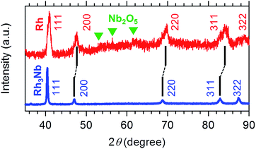 | ||
| Fig. 1 Powder X-ray diffraction (pXRD) profiles for the Rh3Nb precursor (blue) and the developed Rh@NbOx nanocomposite (red). The green triangles correspond to the reflections from Nb2O5. | ||
To investigate the chemical state of the Rh@NbOx nanocomposite, we conducted hard X-ray photoemission spectroscopy (HAXPES; photon energy = 5.9534 keV). Fig. 2a shows the HAXPES spectra for the Rh3Nb precursor and the Rh@NbOx in the Nb 3d region. The Nb 3d5/2- and 3d3/2 photoemission peaks for the Rh3Nb were located at the binding energy of 203.0 and 205.9 eV, respectively.14 The corresponding peaks for the Rh@NbOx were located at the peak positions of 206.9 and 209.7 eV, showing that the Nb cations had a valence close to +5.15
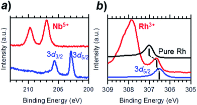 | ||
| Fig. 2 Hard X-ray photoemission spectroscopy (HAXPES) profiles for the Rh3Nb precursor (blue) and the Rh@NbOx (red) in the (a) Nb 3d- and (b) Rh 3d regions. | ||
The HAXPES spectra in the Rh 3d region are presented in Fig. 2b. The Rh 3d5/2 peaks for the Rh3Nb precursor and pure Rh metal were observed at different binding energies, 306.5 and 307.0 eV, respectively. The Rh@NbOx showed a Rh 3d5/2 peak at 306.7 eV, in between those for the Rh3Nb alloy precursor and pristine Rh, indicating the metallic nature of the Rh phase included in the Rh@NbOx. The intense photoemission at 307.9 eV was assigned to a thin oxide layer (Rh3+Oy) over the Rh surface because the emission was prominent when probed with surface-sensitive XPS (photon energy = 1.4866 keV; see Fig. S1†).
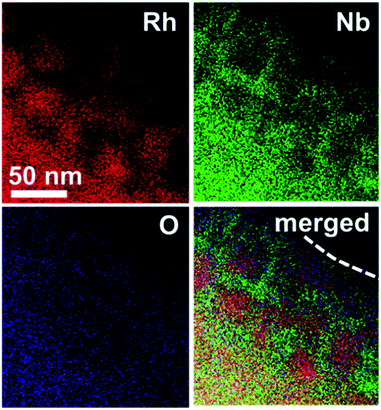
The nanostructure of the Rh@NbOx was investigated with a scanning transmission electron microscope (STEM) equipped with an energy-dispersion spectrometer (EDS) (Fig. 3, see also Fig. S2–S4† for STEM/TEM images). It was demonstrated that Rh was distributed in the bulk and/or over the surface of the Rh@NbOx as nanoparticles with an average size of 50 nm. Importantly, the Rh nanoparticles were connected to each other to form a network structure. The distributions of Nb and O were exclusive to that of Rh, showing that Nb and O formed a NbOx phase. Most of the Rh network was incorporated in the NbOx matrix and partly exposed to the atmosphere (see Fig. S5† for the scanning-electron microscope (SEM) images of the Rh@NbOx). The Rh exposure was surrounded by the NbOx matrix over the catalyst surface, forming a metal/oxide interface around its perimeter.
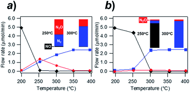
Fig. 4 shows the exhaust-remediation performance of the Rh@NbOx and the control Rh catalyst (see ESI for the experimental details†). The Rh- and Rh@NbOx catalysts were subjected to a steady stream of simulated exhaust (NO![[thin space (1/6-em)]](https://www.rsc.org/images/entities/char_2009.gif) :
:![[thin space (1/6-em)]](https://www.rsc.org/images/entities/char_2009.gif) CO
CO![[thin space (1/6-em)]](https://www.rsc.org/images/entities/char_2009.gif) :
:![[thin space (1/6-em)]](https://www.rsc.org/images/entities/char_2009.gif) He = 1
He = 1![[thin space (1/6-em)]](https://www.rsc.org/images/entities/char_2009.gif) :
:![[thin space (1/6-em)]](https://www.rsc.org/images/entities/char_2009.gif) 1
1![[thin space (1/6-em)]](https://www.rsc.org/images/entities/char_2009.gif) :
:![[thin space (1/6-em)]](https://www.rsc.org/images/entities/char_2009.gif) 98 in volume%; space velocity = 30
98 in volume%; space velocity = 30![[thin space (1/6-em)]](https://www.rsc.org/images/entities/char_2009.gif) 000 h−1; flow rates of NO and CO = 5 μmol min−1) at different temperatures from 200 to 400 °C (see Fig. S6† for the FTIR spectra for the effluent gas).
000 h−1; flow rates of NO and CO = 5 μmol min−1) at different temperatures from 200 to 400 °C (see Fig. S6† for the FTIR spectra for the effluent gas).
The Rh catalyst converted NO to N2 and/or N2O at 250 °C and higher temperatures (Fig. 4a). The flow rate of N2O in the effluent gas was 1.1 μmol min−1 at 250 °C, showing that 44% of the incoming NO was converted to N2O (see bar charts in the inset). The conversion rate from NO to N2O still remained 13% at 300 °C (inset). The residual N2O disappeared from the effluent gas when the temperature exceeded 350 °C. By clear contrast to the trend observed for the Rh catalyst, the Rh@NbOx remediated NO with much lowered N2O emission (Fig. 4b). The N2O concentration in the effluent gas was less than 2% at 250 °C or higher temperatures (see insets). Moreover, the Rh@NbOx fully converted NO to N2 at 300 °C or higher temperatures. Considering the experimental data and the reported lower performance of the palladium-based catalysts than that of Rh-based catalysts, we concluded that the Rh@NbOx was superior to the state-of-the-art PGM catalysts for the N2O emission-free NO remediation at low temperatures.16
Finally, in situ X-ray photoemission spectroscopy (in situ XPS) was conducted to reveal the mechanism behind the N2O emission-free NO remediation over the Rh@NbOx catalyst. A polycrystalline Rh3Nb sample was polished to a mirror finish prior to use in the experiments. Single-crystalline Rh was sliced and mirror-polished to develop the (111) surface (see ESI for details†). The samples were introduced into an ultra-high vacuum (UHV) chamber, cleaned by Ar+ bombardment and exposed to NO gas up to one-monolayer adsorption (1.0 L) at room temperature. The NO-adsorbed sample surfaces were then observed using an XPS spectrometer (monochromatized AlKα; photon energy = 1.4866 keV) in the N 1s- and O 1s regions at elevated temperatures from room temperature to 800 °C.
Fig. 5a shows a contour plot of the N 1s photoemission intensity for the Rh(111) surface as a function of temperature and binding energy. At room temperature, the N 1s emission peak was located at the binding energy of 400.6 eV. This value is assigned to the NO molecules adsorbed onto the Rh surface (NOad).11 With an increase in the surface temperature, the N 1s peak was 2.5 eV shifted at 100 °C toward the lower binding energy, as the result of the dissociation of NOad into Nad and Oad (see Fig. S7†for the in situ XPS spectra in the O 1s region).11 The Nad was thermally desorbed from the surface when the temperature reached 250 °C, diminishing the N 1s emission.
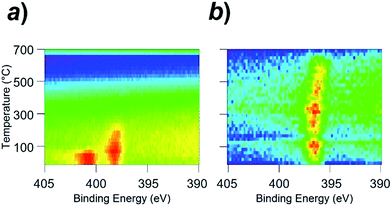 | ||
| Fig. 5 In situ X-ray photoemission spectra (in situ XPS) for (a) the clean Rh surface and (b) Rh3Nb surface. In terms of colour, red indicates high intensity, blue indicates low intensity. | ||
Unlike the Rh surface, as seen in Fig. 5b, the N 1s-emission peak from the NO-adsorbed Rh3Nb surface was located at 396.8 eV at room temperature, which corresponds to the atomic Nad instead of the molecular NOad. This binding energy (396.8 eV) is close to the value for the N 1s emissions from niobium nitride (NbN) and/or niobium oxynitride (NbON), 396.2 eV.15 The Rh3Nb precursor adopted dissociative adsorption of NO to develop the Rh@NbOx phase on the surface, and the nitrogen adatoms were adsorbed not on the Rh site but on the Nb site to form N–Nb bonds.
One of the major paths for the catalytic N2O generation is the combination of NOad and Nad over the catalyst surface (NOad–Nad reaction: NOad + Nad = N2O).17 The low performance of the traditional Rh catalysts for the N2O emission-free NOx remediation is ultimately due to the limited ability of the Rh surface dissociating the NOad only at temperatures higher than 100 °C.18 The Rh@NbOx catalyst can efficiently promote the NOad dissociation because the NbOx matrix adopts the Nad from the Rh surface to form thermodynamically stable NbON at the Rh/NbOx interface.19 Indeed, the Rh@NbOx catalyst containing larger Rh grains and fewer Rh/NbOx interfaces on the surface (Fig. S8†) did not realize the desired N2O-free NO remediation.
Conclusion
In conclusion, we successfully materialized a catalytic nanocomposite comprising nanometer-thick Rh networks and oxygen-deficient NbOx matrices, namely Rh@NbOx, by annealing an Rh3Nb alloy precursor in the NO/CO atmosphere. The synthesized Rh@NbOx nanocomposite exhibited higher catalytic performance than that of pristine Rh catalysts toward the N2O emission-free NO remediation. The enhanced performance of the Rh@NbOx catalyst was attributed to the promoted NO dissociation due to the formation of N–Nb bonds at the metal/oxide interface. The N2O emission-free NO remediation using the Rh@NbOx catalyst will prompt further research and development for high-performance nanocomposite catalysts, realizing reduced impacts to the global atmosphere.Acknowledgements
This study was preliminarily supported by Toyota Motor Corporation and the JST PRESTO program “New Materials Science and Element Strategy”. The HAXPES measurements were performed under the approval of the NIMS Synchrotron X-ray Station (Proposal No. 2015B4605). This study was also supported by NIMS microstructural characterization platform as a program of “Nanotechnology Platform” of the Ministry of Education, Culture, Sports, Science and Technology (MEXT), Japan.References
- A. M. Appel, J. E. Bercaw, A. B. Bocarsly, H. Dobbek, D. L. Dubois, M. Dupuis, J. G. Ferry, E. Fujita, R. Hille, P. J. A. Kenis, C. A. Kerfeld, R. H. Morris, C. H. F. Peden, A. R. Portis, S. W. Ragsdale, T. B. Rauchfuss, J. N. H. Reek, L. C. Seefeldt, R. K. Thauer and G. L. Waldrop, Chem. Rev., 2013, 113, 6621–6658 CrossRef CAS PubMed.
- (a) D. A. Lashof and D. R. Ahuja, Nature, 1990, 344, 529–531 CrossRef CAS; (b) J. T. Houghton, Y. Ding, D. J. Griggs, M. Noguer, P. J. van der Linden, X. Dai, K. Maskel and C. A. Johnson, Climate change 2001: the scientific basis. Cambridge University Press, New York, 2001 Search PubMed; (c) IPCC Fourth Assessment Report, Table 2.14, ch. 2, p. 212 Search PubMed; (d) M. Li, X. Wu, Y. Cao, S. Liu, D. Weng and R. Ran, J. Colloid Interface Sci., 2013, 408, 157–163 CrossRef CAS PubMed; (e) R. G Tonkyn, S. E. Barlow and J. W. Hoard, Appl. Catal., B, 2003, 40, 207–217 CrossRef.
- IPCC AR4 SYR Appendix Glossary, Retrieved 14 December 2008.
- M. Shelef and R. W. McCabe, Catal. Today, 2000, 62, 35–50 CrossRef CAS.
- (a) V. I. Parvulescu, P. Grange and B. Delmon, Catal. Today, 1998, 46, 233–316 CrossRef CAS; (b) M. Shelef and G. W. Graham, Catal. Rev.: Sci. Eng., 1994, 36, 433–457 CrossRef CAS.
- (a) P. Z. Zhdanov, Surf. Sci. Rep., 1997, 29, 31–90 CrossRef; (b) Q. Su, Y. Li, S. Wang and C. Gao, Top. Catal., 2013, 56, 345–351 CrossRef CAS.
- (a) http://www.theicct.org/real-world-exhaust-emissions-modern-diesel-cars, 2014; (b) J. Lelieveld, J. S. Evans, M. Fnais, D. Giannadaki and A. Pozzer, Nature, 2015, 525, 367–371 CrossRef CAS PubMed.
- P. Fornasiero, G. Ranga Rao, J. Kaspar, F. L'Erario and M. Graziani, J. Catal., 1998, 175, 269–279 CrossRef CAS.
- X. Zhao, Y. Cong, F. Lv, L. Li, X. Wang and T. Zhang, Chem. Commun., 2010, 46, 3028–3030 RSC.
- (a) S. S. Kim, S. J. Lee and S. C. Hong, Chem. Eng. J., 2011, 169, 173–179 CrossRef CAS; (b) M. Li, W. X. Wu, Y. Cao, S. Liu, D. Weng and R. Ran, J. Colloid Interface Sci., 2013, 408, 157–163 CrossRef CAS PubMed.
- A. E. Dwight and P. A. Beck, Trans. Metall. Soc. AIME, 1959, 215, 976–979 CAS.
- B. C. Giessen, H. Ibach and N. J. Grant, Trans. Metall. Soc. AIME, 1964, 230, 113–122 CAS.
- B. M. Gatehouse and A. D. Wadsley, Acta Crystallogr., 1964, 17, 1545–1554 CrossRef CAS.
- (a) V. I. Nefedov, M. N. Firsov and I. S. Shaplygin, J. Electron Spectrosc. Relat. Phenom., 1982, 26, 65–78 CrossRef CAS; (b) R. Fontaine, R. Caillat, L. Feve and M. J. Guittet, J. Electron Spectrosc. Relat. Phenom., 1977, 10, 349–357 CrossRef CAS.
- A. Darlinski and J. Halbritter, Surf. Interface Anal., 1987, 10, 223–237 CrossRef CAS.
- (a) S. Salasc, M. Skoglundh and E. Fridell, Appl. Catal., B, 2002, 36, 145–160 CrossRef CAS; (b) Y. Su, K. S. Kabin, M. P. Harold and M. D. Amiridis, Appl. Catal., B, 2007, 71, 207–215 CrossRef CAS; (c) H. Abdulhamid, J. Dawody, E. Fridell and M. Skoglundh, J. Catal., 2006, 244, 169–182 CrossRef CAS.
- L. Kubiak, R. Matarrese, L. Castoldi, L. Lietti, M. Daturi and P. Forzatti, Study of N2O formation over Rh- and Pt-based LNT catalysts, MDPI, 2016 Search PubMed.
- R. J. Baird, R. C. Ku and P. Wynblatt, Surf. Sci., 1980, 97, 346–362 CrossRef CAS.
- V. Schwartz and S. T. Oyama, Chem. Mater., 1997, 9, 3052–3059 CrossRef CAS.
Footnote |
| † Electronic supplementary information (ESI) available. See DOI: 10.1039/c6ra27168e |
| This journal is © The Royal Society of Chemistry 2017 |

