 Open Access Article
Creative Commons Attribution 3.0 Unported Licence
Enhanced positive temperature coefficient behavior of the high-density polyethylene composites with multi-dimensional carbon fillers and their use for temperature-sensing resistors†
Jun-Wei Zha *abc,
Dong-Hong Wua,
Yu Yanga,
Yun-Hui Wua,
Robert K. Y. Lib and
Zhi-Min Dang*ac
aSchool of Chemistry and Biological Engineering, University of Science and Technology Beijing, Beijing 100083, P. R. China. E-mail: zhajw@ustb.edu.cn
bDepartment of Physics and Materials Science, City University of Hong Kong, Tat Chee Avenue, Kowloon, Hong Kong, P. R. China
cState Key Laboratory of Electrical System, Department of Electrical Engineering, Tsinghua University, Beijing 100084, P. R. China. E-mail: dangzm@tsinghua.edu.cn
First published on 14th February 2017
Abstract
Positive temperature coefficient (PTC) materials usually suffer from the low intensity and poor reproducibility, which will limit their service time under harsh thermal control conditions. In this paper, both the functionalized carbon black (CB) and multi-walled carbon nanotubes (MWNT) were introduced into the high-density polyethylene (HDPE) matrix to achieve the improved PTC behaviors. The CB/MWNT/HDPE and CB/HDPE composites were respectively prepared through solution-melt mixing method, and their PTC behaviors were investigated. The results show that the HDPE composites filled with the modified CB exhibit better PTC effect than those filled with raw CB due to the anti-oxidation action of coupling agent. Moreover, it was found that the addition of a small amount of MWNT (0.7 wt%) into the HDPE composites with CB (18 wt%) could make larger intensity (∼6.5) and better reproducibility of PTC behavior. The synergistic effect of the modified CB and MWNT on improving the service time of PTC effect was further explored. The use of multi-dimensional carbon fillers was expected to provide a new route to fabricate high-performance polymeric PTC materials with a potential application as flexible temperature–resistivity sensor.
1. Introduction
The three typical temperature–resistivity behaviors for conductive polymer composites (CPCs) include positive temperature coefficient (PTC) effect, negative temperature coefficient (NTC) effect, and zero temperature coefficient (ZTC). The CPCs are usually fabricated by mixing an insulating polymer matrix with different types of conductive fillers such as metallic powders,1 carbon black (CB),2–6 carbon nanotubes (CNTs),7–10 carbon fiber (CF),11,12 graphite nanofibers (GNF),13,14 etc. The resistivity of PTC materials has a sharp increase around the melting temperature (Tm) of crystalline polymer. This effect is widely used in the electrical industry, such as, the over current protective device, self-regulating heater,15 and micro-switch sensors,16 etc. Compared with other traditional materials, the polymer-based PTC materials have many advantages, such as, excellent formability, flexibility, light weight, large energy efficiency and high security.17 However, these PTC materials also have some disadvantages, such as NTC effect, poor reproducibility and mechanical property. Therefore, the high-performance PTC materials still remain to be explored in the future.As previously reported, a lot of methods were adopted to solve the problems above. From the point of polymer matrix, Wei et al. studied the CB/PP/UHMWPE composites with a segregated structure by using binary polymer granules, and achieved an ultralow percolation threshold, a wider PTC region and a zero NTC effect.18 From the point of the filler, Shen et al. investigated the addition of the mixture of CB and CF to improve the PTC effect of polymer-based composites.19 It was concluded that the electrons were transported over the CFs, and the CFs can be considered as the bridges to connect the CB particles. This network structures could increase the density of conductive paths, resulting in the reduced electrical resistivity.20,21 Dang's group remarkably improved the dispersion of conductive fillers by surface modification method, which could largely decrease the resistivity of the PTC materials.22–24 Some researchers employed the carboxylated MWNT (c-MWNT) to increase the conductivity of polymer-based PTC composites.25–27 However, some intrinsic drawbacks still exist in the materials,28,29 such as, (1) low PTC intensity resulting from the oxidation of conductive particles at elevated temperature and (2) poor PTC reproducibility due to the irreversible motion of conductive particles during thermal cycling process. These drawbacks greatly restrict the application of the polymer-based PTC materials in some critical circumstances, such as, high temperature, large applied currents, and high applied voltages.
In order to overcome the intrinsic drawbacks in the traditional CB filled polymeric PTC materials, CB nanoparticles were usually modified by the silane coupling agent and titanate coupling agent. Meanwhile, the MWNT was chosen as the second filler due to their excellent electrical, mechanical and thermal properties.30–33 In this study, the functionalized-CB and MWNT were well dispersed in the HDPE matrix by using solution-melt mixing method, and the polymeric PTC materials with low filler content, high PTC intensity and stable PTC repeatability were achieved. The synergistic effects of the modified-CB and MWNT on the intensity and reproducibility of PTC behavior of the HDPE composites were also discussed.
2. Experimental
2.1. Materials
HDPE with melt flow (at 190 °C and under force of 2.16 kg) of 0.5 g/10 min, density of 0.953 g cm−3 and melting point of about 130 °C (measured by differential scanning calorimetry) was supplied by Lyondell Basell Industries, Holland. CB (Vxc-68) with a dibutylphthalate (DBP) absorption value of 123 ± 5, an iodine number of 68 ± 5 mg g−1 and diameter of 20–50 nm was supplied by Cabot Corporation. MWNTs with the diameter of 8–15 nm and length of ∼50 μm were supplied by Shenzhen Nanotech Port Co. Ltd.2.2. Surface modification of the CB nanoparticles
Prior to use, the surface of CB nanoparticles was modified using 1.0 wt% silane coupling agent (A171) and titanate coupling agent (NDZ-311) to improve their dispersion and compatibility in the HDPE matrix. Firstly, the silane coupling agent was dissolved in methanol, and the titanate coupling agent was dissolved in isopropanol, respectively. Secondly, the two mixed solvents were respectively mixed with CB in a ball mill for 2 h to enable the coupling agent to evenly cover the CB surface. After vaporizing the solvent, the silane coupling agent was further reacted with CB at 120 °C in a vacuum oven for 2 h and the titanate coupling agent dried at 70 °C in a vacuum oven for 2 h, and then CB was filtered by the distilled water and then dried in a vacuum oven for 4 h. Finally, two kinds of modified CB denoted as CB-1 (modified by A171) and CB-2 (modified by NDZ-311) were obtained. For comparison, the unmodified CB nanoparticles were denoted as CB-0.2.3. Fabrication of the HDPE composites
The HDPE composites were prepared by solution-melt mixing method as follows. The MWNT and CB were firstly dispersed in ethanol by ultrasonication for 1 h. Subsequently, prior to the melt mixing, the mixture was mixed with the HDPE uniformly and then dried at 70 °C in a vacuum oven for 5 h. The HDPE blends with various amounts of MWNTs and CB were prepared using Haake rheometer at 180 °C and 60 rpm for 10 min. Finally, the blends prepared by this master batch process were compressed with a hot press under 20 MPa at 180 °C for 10 min, and then slowly cooled down to room temperature under pressure and the CB/MWNT/HDPE composites with a thickness of 1 mm and a diameter of 12 mm were obtained. For comparison, the CB/HDPE composites were also prepared.2.4. Characterization
The functional groups of modified CB nanoparticles were confirmed by Fourier transform-infrared (FTIR) spectra using KBr pressed disks (Thermo Nicolet 6700, USA) with the characteristic absorption from 4000 to 400 cm−1. All samples were tested at room temperature. Morphology of the cross-section surface of HDPE composites was observed using a field-emission scanning electron microscopy (SEM, S-4700, Hitachi, Japan) with accelerating voltage of 20 kV. The samples were fractured in liquid nitrogen and the fractured surface was sputtered with gold before SEM observation. Thermal behaviors of the composites were measured by differential scanning calorimetry (DSC, TA-60WS) at a heating and cooling rate of 5 °C min−1 under a nitrogen atmosphere. The PTC effect of HDPE composites was measured using two-probe method by employing a digital multimeter when each sample was heated in the oven at a rate of 5 °C min−1. A thermocouple was touched on the center of sample surface and the temperature data can be obtained timely. In order to investigate the reproducibility of the PTC behavior, the electric resistivity measurements were conducted for ten heating cycles. Each sample was about 12 mm in diameter and the thickness was measured with a micrometer before using. The two sides of the samples were painted uniformly by one thin silver paste as an electrode to reduce the contact resistance and then were dried in the oven for 1 h.3. Results and discussion
3.1. Chemical structures of the nanoparticles
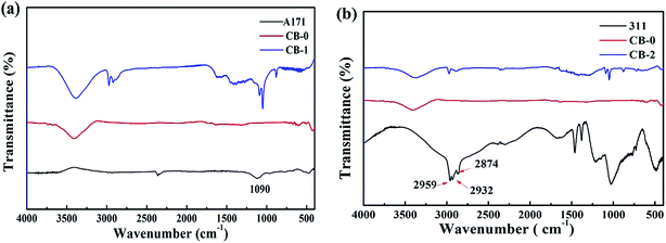
The FT-IR spectra of the coupling agent, unmodified CB (CB-0) and modified CB nanoparticles (CB-1 and CB-2) are shown in Fig. 1. Compared with the CB-0, the new peak at around 1090 cm−1 for the CB-1 shown in Fig. 1a indicates that the silicon oxygen bonds were reacted with hydrogen bonds. As shown in Fig. 1b, the absorption peaks at 2959 cm−1, 2932 cm−1 and 2874 cm−1 are attributed to the C–H stretching vibration of the methyl group. Thus, the CB nanoparticles have been functionalized by the coupling agent of A171 and NDZ-311, respectively, which would give rise to good dispersion and miscibility of CB-1 and CB-2 in HDPE matrix. Schematic diagram of modified CB by the coupling agents A171 and NDZ-311 is shown in Fig. S1.†3.2. Microstructure of CB/HDPE composites with and without MWNT
Fig. 2 shows SEM images of fractured cross section of the CB/HDPE composites with and without MWNT. It can be seen from Fig. 2a1 shows that some CB-0 particles agglomerate in the matrix. However, compared with the CB-0, it is difficult to observe the agglomeration of CB-1 and CB-2 as shown in Fig. 2a2 and a3. This indicates that the modification of CB with coupling agent of A171 and NDZ-311 leads to its good dispersion in the HDPE matrix. Meanwhile, it can be seen that a little MWNTs are uniformly distributed in the composites as shown in Fig. 2b1–b3. The small amount of MWNTs dispersed in the CB/HDPE composites may help the reformation of the conductive paths caused by volume expansion during the repeated heating–cooling cycles.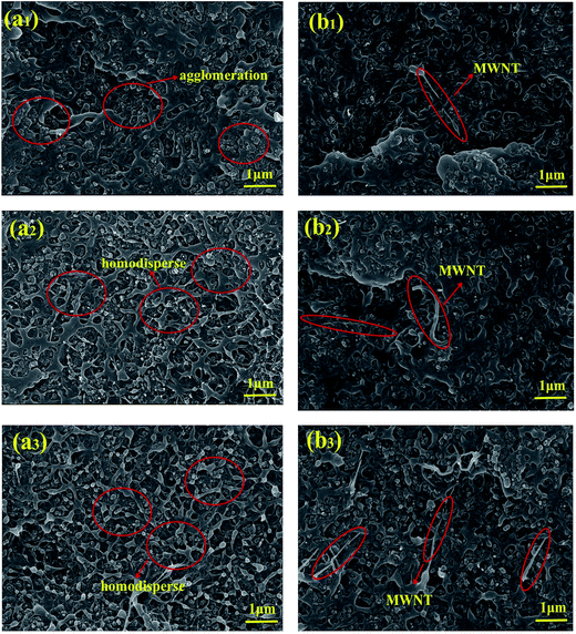 | ||
| Fig. 2 SEM images of the HDPE composite (a) with CB (20 wt%) (a1) CB-0, (a2) CB-1 and (a3) CB-2, and (b) with CB/MWNT (18/0.7 wt%) (b1) CB-0, (b2) CB-1 and (b3) CB-2, respectively. | ||
3.3. Differential scanning calorimetry (DSC) curves
To make a further understanding of the influence of filler content on PTC effect, the melting behaviors of pure HDPE, CB/HDPE and CB/MWNT/HDPE composites were characterized by DSC measurement. The melting curves of pure HDPE and HDPE filled with 20 wt% CB are shown in Fig. 3a. For pure HDPE, it can be seen that there is only one melting peak at about 131 °C. Notably, the melting peaks of the CB/HDPE composites are slightly decreased to 130 °C. This suggests that the introduction of CB has little effect on the intrinsic thermal properties of HDPE matrix. Moreover, Fig. 3a also shows the coupling agents of A171 and NDZ-311 have little influence on melting peaks. Similarly, the melting curves of pure HDPE and HDPE filled with CB/MWNT (18/0.7 wt%) are shown in Fig. 3b. The melting peak of HDPE filled with CB/MWNT (18/0.7 wt%) is also at 131 °C as shown in Fig. 3b. Meanwhile, the CB nanoparticles modified by coupling agent of A171 and NDZ-311 shows little influence on the melting peak which is also at 130 °C. The melting peak has a deep influence on the thermal–electrical properties, and the conductive network will have a sudden change.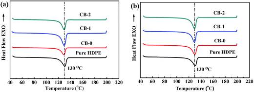 | ||
| Fig. 3 DSC curves of (a) pure HDPE and CB/HDPE (20 wt%) nanocomposite filled with CB-0, CB-1, CB-2, and (b) CB/MWNT/HDPE (18/0.7 wt%) filled with CB-0, CB-1 and CB-2, respectively. | ||
3.4. PTC behavior of the CB/HDPE composites
PTC intensity is defined as the logarithm of the ratio of the maximum resistivity to the resistivity at room temperature as follows:| PTC intensity = log(ρmax/ρRT) | (1) |
Fig. 4 shows the effect of coupling agent of A171 and NDZ-311 on PTC behavior of the HDPE composites. The mass fraction of CB is fixed as 20 wt% which is near percolation threshold of the system, which is shown in Fig. S3.† It can be seen that the PTC intensities of HDPE composites filled with CB-0, CB-1 and CB-2 are 5.45, 6.29 and 6.45, respectively. It is because that the dispersion of modified CB in HDPE matrix is more uniform than that of the CB-0, and the coupling agents of A171 and NDZ-311 show various effects in PTC intensities. The increase of PTC intensities of the CB-1/HDPE and CB-2/HDPE composites comes from the reaction of coupling agent with polar groups on the surface of CB that prevent the movement of the electrons. Moreover, the reaction of coupling agent alleviates the oxygen and increases the interfacial action between CB and HDPE, which could improve the PTC intensities. Thus, the whole conductivity increase due to the elimination of impurities and the good interface action between CB and HDPE.
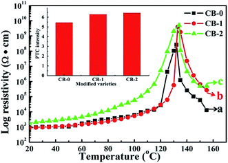 | ||
| Fig. 4 Resistivity–temperature behaviors of the CB/HDPE (20 wt%) composites; (a) CB-0, (b) CB-1 and (c) CB-2. Inset is the PTC intensity of the composites calculated according to eqn (1). | ||
3.5. PTC behavior of the CB/MWNT/HDPE composites
Fig. 5 shows the log volume resistivity of HDPE composites filled with the CB-0 (18 wt% and 20 wt%, respectively) and different MWNT contents as a function of temperature. It can be seen that the log resistivities of CB-0/MWNT/HDPE composites at room temperature are much lower than that of CB-0/HDPE. With increasing the content of MWNT from 0.3 to 2 wt%, their resistivities at room temperature and their maximum resistivity decrease. This is because that MWNT has the special one-dimensional nanotube structure with larger contact surfaces to form conductive paths than CB particles with spherical shape do. Thus, MWNTs play a role of bridge-linked on connecting CB particles to easily form conductive network in the HDPE matrix, thus resulting in higher electrical conductivity. Moreover, there is a close relationship between the PTC intensity and MWNT contents. As shown in the PTC charts (inset of Fig. 5), the CB-0/HDPE (18 wt%) composites with 0.7 wt% MWNT loading show the highest PTC intensity of 5.76, while the CB-0/HDPE (20 wt%) composites with 2 wt% MWNT show the lowest PTC intensity of 2.29. The resistivity peaks are observed at 132 °C for CB-0/HDPE nanocomposites and at 135 °C for CB-0/HDPE nanocomposites filled with MWNTs, respectively. The temperatures are slightly higher than the melting point of HDPE (which is approximately 130 °C, as determined by DSC from Fig. 3). These results may be due to the fact that the MWNTs bridge the non-contacting CB particles and connect the short conducting paths, thus forming a network structure shown in Fig. 2b. Therefore, the resistivity of the composites containing CB and MWNTs is not as sensitive to changes in temperature as that of the composites containing only single filler before the transition temperature. That is, the polymer composites require enough efficient volume expansion to break off the formed network at higher temperature.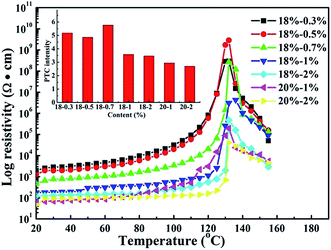 | ||
| Fig. 5 Temperature dependency on the resistivity of CB-0/HDPE (18/82 wt%) and CB-0/HDPE (20/80 wt%) composites with various MWNTs contents. Inset is the PTC intensity of composites calculated according to eqn (1). | ||
3.6. Reproducibility of PTC behavior of the CB/MWNT/HDPE composites
The resistivities of CB-0/HDPE composites and modified-CB/HDPE filled with 0.7 wt% MWNTs as function of temperature during ten heating–cooling cycles are presented in Fig. 6. As shown in the inset of Fig. 6a, when the heating–cooling cycle is up to ten times, the PTC intensity of CB-0/HDPE composites decrease from 5.94 to 5.15, showing poor reproducibility. As shown in Fig. 6a, it is found that the first cycle curve is obviously different from the subsequent curves and the room temperature resistivity increases with increasing number of heating cycles. This phenomenon may be attributed to the volume expansion of matrix which would break the conductive networks formed by CB. Due to the weak interfacial adhesion between the CB nanoparticles and HDPE matrix, it is difficult for the conductive paths of CB to reform during the repeated heating cycles. Moreover, compare with the CB-0/HDPE, the CB-1/HDPE and CB-2/HDPE composites show the excellent reproducibility as shown in Fig. 6b and c. We can see from Fig. 6b that the PTC intensity of the CB-1/HDPE increases to 6.0, which still keep good reproducibility after ten heating–cooling cycles. Besides, the PTC intensity of CB-2/HDPE composites is up to 6.5 as shown in Fig. 6c. This is because that the polymer chains and fillers were connected by the coupling agent through chemical bonding, resulting in relative stable conductive networks. The coupling agent of A171 and NDZ-311 can not only separate CB nanoparticles during the expansion of matrix at high temperature, but also could make them return their original position when the temperature is cooled down. Compare with A171, the coupling agent of NDZ-311 shows better effectiveness in improving the PTC intensity. That is because the NDZ-311 has long chain covered on the surface of CB nanoparticles and shows better anti-oxidation with the increasing temperature.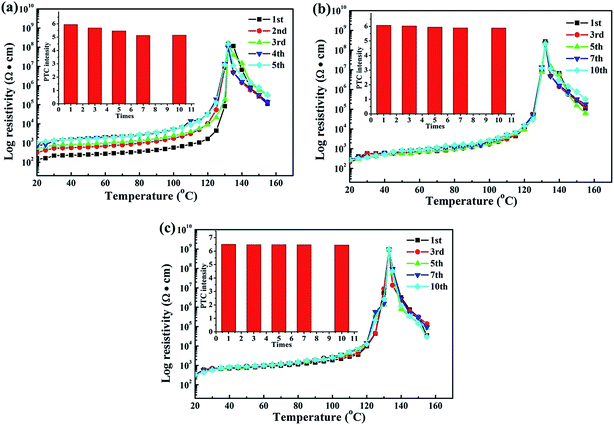 | ||
| Fig. 6 Reproducibility of the CB/MWNT/HDPE (18/0.7 wt%) composites filled with (a) CB-0, (b) CB-1 and (c) CB-2. Inset is the PTC intensity of composites calculated according to eqn (1). | ||
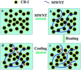
Fig. 7 shows schematic diagram of PTC behavior of the HDPE composites filled with CB-2 and MWNT during heating–cooling process. The coupling agents of NDZ-311 were covered on the CB surface with chemical bond by ball mill, which can forms a bonding layer. This means that the modified CB nanoparticles have better anti-oxidation ability and keep better electrical conductivity at elevated temperature, compared with the raw CB. With the thermal volume expansion in the matrix, some conductive networks will be broken as shown in Fig. 7c. As the movement of CB-2 nanoparticles and rupture of MWNTs near the melt point, the conductive network would be broken, and the resistivity has a great increasing trend. With the decrease of temperature, it will result in volume shrinkage in the HDPE matrix, and the CB-2 nanoparticles and MWNTs corporately rebuilt the conductive network. The MWNTs play an important role on decreasing the volume expansion and maintaining the position of CB particles in a relative stable conductive networks. It helps to make high-performance PTC materials using the synergistic effect between the modified CB particles and MWNTs.
To demonstrate their potential applications as the temperature-sensing resistor, the typical CB/MWNT/HDPE (18/0.7 wt%) composite resistors under a low voltage were fabricated and their real-time PTC effect as illustrated in Fig. 8. The composites resistor at room temperature (25 °C) was considered as the initial state, it can be seen that the LED light in the circuit is bright. With increasing the temperature, the LED light becomes dark as shown in Fig. 8b due to the increased resistivity of the composites resistor. However, the LED light is found to become bright again as shown in Fig. 8c, which is due to the reformation of conductive networks during the cooling process. Thus, it can be concluded that the CB/MWNT/HDPE composite have the great potential to be used as one good candidate for heat sensitive resistor applications.
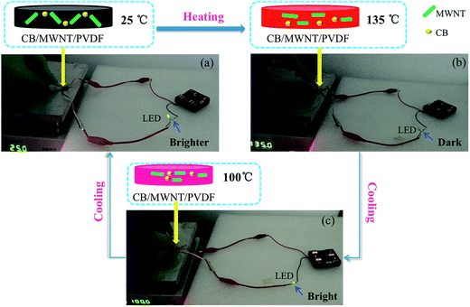 | ||
| Fig. 8 Potential application of the temperature-sensing resistor during the heating–cooling cycles (a) 25 °C, (b) 135 °C and (c) 100 °C. | ||
4. Conclusions
In this work, CB nanoparticles were successfully modified by two kinds of coupling agent (A171 and NDZ-311) through solution mixing method. Then the bonding layer was formed on the surface of CB, which can effectively prevent the oxidation of amorphous CB particles at elevated temperatures and facilitate the compatibility between the CB and HDPE matrix. By addition of 20 wt% CB modified with A171 and NDZ-311, PTC intensity of the HDPE composites increased by 15.4% and 18.3%, respectively. Besides, it is worth noting that the addition of small amount of MWNTs (0.7 wt%) can obviously decrease the CB concentration and ensure larger PTC intensity. This is because that the MWNT could serve as one bridge to connect the CB nanoparticles, which could reduce volume expansion of the HDPE matrix and facilitate the formation of conductive networks. Besides, after ten thermal cycles, the CB-1/MWNT/HDPE (18/0.7/82) and CB-2/MWNT/HDPE (18/0.7/82) exhibited higher stability and reproducibility of PTC effect, compared with the CB-0/MWNT/HDPE (18/0.7/82). Thus, the addition of functionalized CB and MWNT into HDPE matrix can realize the improved intensity and reproducibility of PTC effect. This work could provide an effective method to increase the service time of polymeric PTC material under harsh thermal control conditions.Acknowledgements
This work was financial supported by National Natural Science Foundation of China (No. 51622701, 51377010 and 51425201), Ministry of Education of China through Doctor Project (No. 20130006130002), the National Basic Research Program of China (973 Program, 2015CB654603), Hong Kong Scholar Program (XJ 2014048), China Postdoctoral Science Foundation Funded Project (No. 2015M580983), and the Fundamental Research Funds for the Central Universities (No. FRF-BR-15-008B).References
- S. P. Bao, G. D. Liang and S. C. Tjong, Carbon, 2011, 49, 1758–1768 CrossRef CAS.
- C. Zhang, C. A. Ma, P. Wang and M. Sumita, Carbon, 2005, 43, 2544–2553 CrossRef CAS.
- M. Wen, X. Sun, L. Su, J. Shen, J. Li and S. Guo, Polymer, 2012, 53, 1602–1610 CrossRef CAS.
- A. Kono, K. Shimizu, H. Nakano, Y. Goto, Y. Kobayashi, T. Ougizawa and H. Horibe, Polymer, 2012, 53, 1760–1764 CrossRef CAS.
- S. H. Bae, R. K. Layek, S. H. Lee, T. Kuila, N. H. Kim and J. H. Lee, Polym. Test., 2016, 50, 83–93 CrossRef CAS.
- E. S. Park, Macromol. Mater. Eng., 2006, 291, 690–696 CrossRef CAS.
- Y. Zeng, G. Lu, H. Wang, J. Du, Z. Ying and C. Liu, Sci. Rep., 2014, 4, 6684 CrossRef PubMed.
- F. Liu, X. Zhang, W. Li, J. Cheng, X. Tao, Y. Li and L. Sheng, Composites, Part A, 2009, 40, 1717–1721 CrossRef.
- B. C. Bai, S. C. Kang, J. S. Im, S. H. Lee and Y. S. Lee, Mater. Res. Bull., 2011, 46, 1391–1397 CrossRef CAS.
- E. Asare, A. Basir, W. Tu, H. Porwal, H. Zhang, Y. Liu, J. Evans, M. Newton, T. Peijs and E. Bilotti, Nanocomposites, 2016, 2, 58–64 CrossRef CAS.
- Y. Xi, H. Ishikawa, Y. Bin and M. Matsuo, Carbon, 2004, 42, 1699–1706 CrossRef CAS.
- Q. Chen, Y. Xi, Y. Bin and M. Matsuo, J. Polym. Sci., Part B: Polym. Phys., 2008, 46, 359–369 CrossRef CAS.
- Q. Li, J. W. Kim, T. H. Shim, Y. K. Jang and J. H. Lee, Adv. Mater. Res., 2008, 47–50, 226–229 CrossRef CAS.
- F. He, S. Lau, H. L. Chan and J. Fan, Adv. Mater., 2009, 21, 710–715 CrossRef CAS.
- Y. Song and Q. Zheng, Polym. Int., 2004, 53, 1517–1522 CrossRef CAS.
- A. Rybak, G. Boiteux, F. Melis and G. Seytre, Compos. Sci. Technol., 2010, 70, 410–416 CrossRef CAS.
- Y. Bao, L. Xu, H. Pang, D. X. Yan, C. Chen, W. Q. Zhang, J. H. Tang and Z. M. Li, J. Mater. Sci., 2013, 48, 4892–4898 CrossRef CAS.
- Y. Wei, Z. Li, X. Liu, K. Dai, G. Zheng, C. Liu, J. Chen and C. Shen, Colloid Polym. Sci., 2014, 292, 2891–2898 CAS.
- L. Shen, F. Q. Wang, H. Yang and Q. R. Meng, Polym. Test., 2011, 30, 442–448 CrossRef CAS.
- B. J. Kim, K. M. Bae, M. K. Seo, K. H. An and S. J. Park, Mater. Sci. Eng., A, 2011, 528, 4953–4957 CrossRef CAS.
- Z. Zhou, S. Wang, Y. Zhang and Y. Zhang, J. Appl. Polym. Sci., 2006, 102, 4823–4830 CrossRef CAS.
- H. P. Xu, Z. M. Dang, D. H. Shi and J. Bai, J. Mater. Chem., 2008, 18, 2685–2690 RSC.
- H. P. Xu, Z. M. Dang, M. J. Jiang, S. H. Yao and J. Bai, J. Mater. Chem., 2008, 18, 229–234 RSC.
- M. J. Jiang, Z. M. Dang, S. H. Yao and J. Bai, Chem. Phys. Lett., 2008, 457, 352–356 CrossRef CAS.
- T. Jeevananda, N. H. Kim, J. H. Lee, S. Basavarajaiah, U. M. V. Deepa and C. Ranganathaiah, Polym. Int., 2009, 58, 775–780 CrossRef CAS.
- P. Dinesh, N. M. Renukappa and Siddaramaiah, Integr. Ferroelectr., 2010, 116, 128–136 CrossRef CAS.
- T. Jeevananda, O. G. Palanna, J. H. Lee, Siddaramaiah and C. Ranganathaiah, Adv. Mater. Res., 2010, 123–125, 59–62 CrossRef CAS.
- E. S. Park, Macromol. Mater. Eng., 2006, 291, 690–696 CrossRef CAS.
- N. Roy, R. Sengupta and A. K. Bhowmick, Prog. Polym. Sci., 2012, 37, 781–819 CrossRef CAS.
- X. J. He, J. H. Du, Z. Ying, H. M. Cheng and X. J. He, Appl. Phys. Lett., 2005, 86, 062112 CrossRef.
- Y. Zeng, G. Lu, H. Wang, J. Du, Z. Ying and C. Liu, Sci. Rep., 2014, 4, 6684 CrossRef PubMed.
- Y. Fang, J. Zhao, J. W. Zha, D. R. Wang and Z. M. Dang, Polymer, 2012, 53, 4871–4878 CrossRef CAS.
- J. W. Zha, W. K. Li, R. J. Liao, J. Bai and Z. M. Dang, J. Mater. Chem. A, 2013, 1, 843–851 CAS.
Footnote |
| † Electronic supplementary information (ESI) available. See DOI: 10.1039/c6ra27367j |
| This journal is © The Royal Society of Chemistry 2017 |

