DOI:
10.1039/C6RA27618K
(Paper)
RSC Adv., 2017,
7, 6336-6344
Application of graphene–polymer composite heaters in gas-assisted micro hot embossing†
Received
1st December 2016
, Accepted 10th January 2017
First published on 18th January 2017
Abstract
This paper reports a novel hot embossing technique using rapid heating and uniform pressure for replication of microstructures on polymeric substrates. The rapid heating is made possible by a graphene–polymer composite heater that makes use of the exceptional thermal and electrical properties of graphene. The uniform embossing pressure is achieved by using gas as the pressing medium. A heating rate of 14 °C s−1 can be achieved by applying a voltage of 44 V to a heating area of 30 mm × 30 mm. A facility that integrates graphene-based heating and gas-assisted embossing is designed and implemented. Three microstructures, namely, microlens array, V-groove, and microcylinder array, are successfully replicated on three polymeric substrates. The accuracy and uniformity of replication over the area of 50 mm × 50 mm is also confirmed. Furthermore, the thermal cycle time is reduced to less than 30 s. This study proves the great potential of using graphene–polymer composite heaters in gas-assisted micro hot embossing for replication of microstructures for various applications.
1. Introduction
Because the technology known as microelectromechanical systems (MEMS) has developed rapidly, cost-effective replication of large-area microscale structures has gained popularity in industry. Among the various microfabrication techniques is hot embossing, a flexible and low-cost method that is regarded as one of the most promising processes for fabricating microscale features with high precision and quality, especially for biomedical and optical applications.
The standard hot embossing process consists mainly of three steps. First, the polymer substrate and the embossing tool are heated beyond the glass transition temperature (Tg) of the polymer. Then, the polymer substrate is pressurized and shaped at embossing temperature. Finally, both the substrates and the embossing tool are cooled to below Tg after embossing. It can be seen that the thermal cycle of the polymer is a parameter that must be considered in the hot embossing process. An inherent problem with the standard hot embossing process is the large thermal mass of the embossing tool and polymer substrate, which results in long cycle times on the order of 10 min or longer and limits the capability of mass production. To address this problem, new techniques that can achieve rapid thermal cycling are needed.
In recent years, various rapid heating methods for hot embossing applications have been reported. Infrared laser-, or laser/IR-, assisted microembossing process was developed to shorten the cycle time by using an IR-absorbent polymer substrate and an IR-transparent mold.1 Reductions in cycle time were reported for ultrasonic hot embossing of microstructures.2–5 High-frequency induction heating was demonstrated to be effective in productivity enhancement in hot embossing.6 However, either significant modifications in tool materials are necessary to fulfil the IR-transparent requirement, or special implementations must be made in the embossing facility for ultrasonic or induction heating embossing.
On the other hand, graphene, a two-dimensional crystal material of atomic thickness, has attracted much attention due to its high electrical and thermal conductivity. The resistivity of graphene would be 10−6 Ω cm, which is less than that of copper. The thermal conductivity of graphene is approximately 5300 W m−1 K−1, compared with the thermal conductivity of silver of approximately 400 W m−1 K−1 at room temperature. Consequently, a novel rapid hot embossing system was developed by utilizing a graphene coating technology on micro-patterned silicon molds to implement rapid heating.7 But the preparation of graphene was highly expensive and sophisticated. To overcome these disadvantages, polymer composites reinforced with graphene have been investigated recently.8–13 It has been proven that graphene–polymer composites with excellent electrical conductivity can be used to fabricate electric heating materials and device14,15 which are a kind of resistor that effectively converts electrical energy into thermal energy in the form of heat. There has been no prior research using graphene–polymer composites in hot embossing. In this study, a high-performance heater utilizing a graphene–polymer composite to implement rapid heating for hot embossing was developed. A polyimide (PI) substrate was coated with the graphene–polymer composite to function as a heater. First, the electric heating behavior of the graphene-based heater was investigated, including heating rate, maximum temperature, operational repeatability, and stability. Afterward, a hot embossing facility integrating this graphene-based heater and gas pressurizing, a mechanism proven to deliver uniform pressure distribution,16,17 was designed and implemented. Three microstructures including microlens array, micro V-groove, and micro-cylinder array were replicated on polycarbonate (PC), cyclo-olefin polymers (COP), and polylactide (PLA), respectively. The accuracy and uniformity of the replications were measured and verified.
2. Experimental
2.1 Preparation of graphene–polymer composite heater
Graphene electrically conductive ink (I-EP32, Enerage Inc., Taiwan), composed of graphene powders (∼47%) and polyurethane (PU) resin (20%), is a type of graphene–polymer composite. Different ink viscosities can be produced by adjusting the ratio of graphene powders to resin. The viscosity of the graphene ink used in this study was 6 cP, while the sheet resistance was less than 20 Ω, as measured by the four-point probe method.
The PI substrate, purchased from Chang Yow Plastic Co., Ltd, was coated with the graphene ink. PI has a high maximum operating temperature of 360 °C and a low coefficient of thermal expansion (CTE) of 5 × 10⁻⁵ m (m−1 K). The thickness of the PI substrate was 1.58 mm.
The graphene–polymer composite heater was fabricated by applying the graphene conductive ink on the PI plate by dip coating (refer to the ESI in S1†). The coating speed was set to 5 m min−1 and the resulting thickness of the graphene–polymer composite layer was approximately 3 μm. Then, the graphene–polymer composite heater was thermally cured at 130 °C for 40 min. Finally, two copper sheets were glued to both ends of the graphene–polymer composite layer to serve as electrodes for supplying the input voltage to the heater. The electrical resistance of the graphene-based heater was less than 50 Ω.
2.2 Facility for rapid heating gas-assisted embossing
As shown in Fig. 1, the graphene-based heater was placed on a hollow support with the graphene–polymer layer facing down. This prevented direct contact between the graphene–polymer layer and the embossing tool, or mold, which would cause degradation of the graphene-based heater (refer to the ESI in S2†). The microstructure mold and the polymer substrate were then stacked on the graphene-based heater. After the voltage was applied, heat generated from the graphene–polymer composite layer was conducted through the thin PI plate to the mold, and then to the polymer substrate. Next, the entire embossing setup was placed inside a gas-assisted embossing facility, as shown in Fig. 2. The gas-assisted embossing facility consisted of an upper chamber with an air valve for supplying nitrogen gas and a lower chamber in which to install the embossing setup. A silicone sealing film of 3 mm thickness was placed between the two chambers to separate the nitrogen gas in the upper chamber from the lower chamber. Furthermore, a type K thermo couple was employed for temperature measurement.
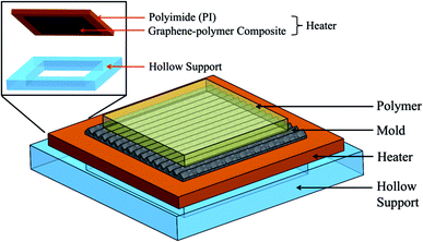 |
| | Fig. 1 Embossing setup. | |
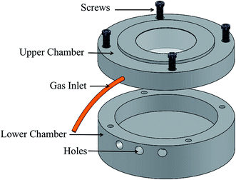 |
| | Fig. 2 Upper and lower chambers of the embossing facility. | |
2.3 Rapid heating gas-assisted embossing process
As shown in Fig. 3, the rapid heating gas-assisted embossing process consists of four steps: (a) place the heater/mold/polymer stack in the lower chamber. (b) Place the silicone sealing film between the chambers and lock the chambers with screws. (c) Apply a voltage to the electrodes of the heater for rapid heating and blow nitrogen gas into the chambers to achieve a uniform pressure. At this step, polymer substrate is heated beyond the glass transition temperature (Tg). Then the polymer is pressurized and shaped at embossing temperature. After the mold cavity is filled with molten polymer, enter the last step: (d) cool the mold and the polymer, expel the nitrogen gas, and, finally demold. By virtue of the excellent thermal conductivity of the graphene-based heater, heat can transfer to the mold and polymer efficiently.
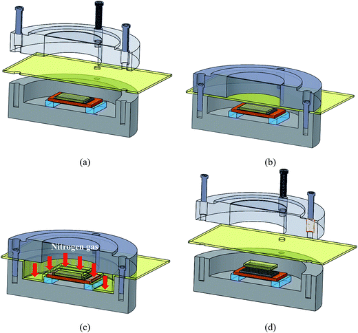 |
| | Fig. 3 Schematic of the rapid heating gas-assisted embossing process. | |
2.4 Molds with microstructures and polymeric substrates
Three types of structures were used for the mold patterns including microlens array, micro V-groove, and microcylinder array, as shown in Fig. 4. Detail dimensions of the three microstructures are shown in Table 1. Three experiments were carried out to replicate the microlens array, microcylinder array, and micro V-groove onto PC, PLA, and COP, respectively. The area of all three of these polymeric substrates was 50 mm × 50 mm. Their thickness and Tg are shown in Table 2. The embossing temperatures used for PC, COP, and PLA were 170 °C, 160 °C and 85 °C, respectively. The embossing pressure were all 0.6 MPa.
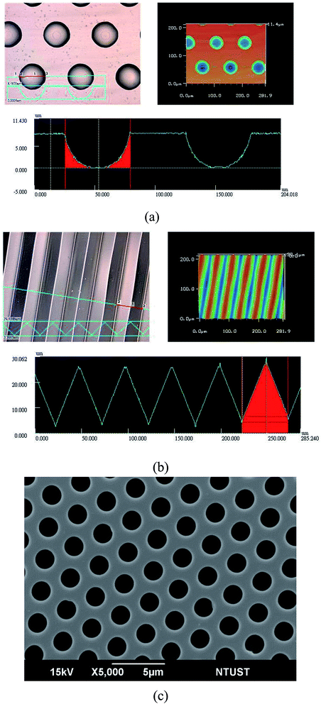 |
| | Fig. 4 Surface scanning, surface profile, and 3D profile of two microstructures by LSCM – (a) microlens array and (b) micro V groove – and (c) SEM image of microcylinder array on the original molds. | |
Table 1 The detail dimensions of the three microstructures
| Patterns |
Lens array |
Cylinder array |
V groove |
| Height (μm) |
8 |
2.79 |
24.09 |
| Diameter (μm) |
50 |
2.1 |
— |
| Pitch (μm) |
100 |
2.84 |
50 |
Table 2 Process parameters adopted in rapid heating gas-assisted hot embossing
| Experiment |
1 |
2 |
3 |
| Polymeric substrate |
PC |
PLA |
COP |
| Tg (°C) |
150 |
65 |
140 |
| Thickness (μm) |
175 |
200 |
2000 |
| Microstructure |
Lens array |
Cylinder array |
V groove |
| Embossing temperature (°C) |
170 |
85 |
160 |
| Embossing pressure (MPa) |
0.6 |
0.6 |
0.6 |
| Input voltage (V) |
54 |
54 |
54 |
| Heating time (s) |
11 |
3 |
9 |
3. Results and discussion
3.1 Electric heating performance
The electric heating performance of various graphene-based heaters differing in heating area and subjected to various voltages was investigated. Temperatures of the graphene-based heater were measured by infrared camera (F20, Nippon, Nippon Avionics Co., Ltd, Japan). A typical temperature distribution, measured at the center of nine equally divided areas during heating, is shown in Fig. 5. It exhibits heating uniformity of the graphene-based heater with a maximum temperature differences of 10.9 °C. Because of the good heating uniformity, the temperature of the center of the heater could roughly be treated as the representative temperature of the whole heater. The center temperature of the heater was measured by infrared camera to control the temperature during the process and recorded for heating curve.
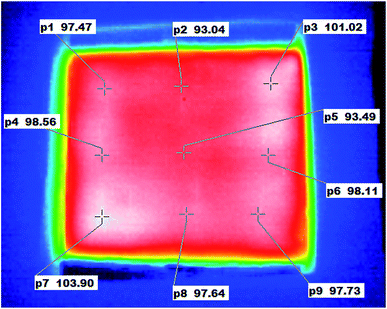 |
| | Fig. 5 Temperature distribution on the graphene-based heater (40 mm × 40 mm) as measured by infrared camera. | |
3.1.1 Heating rate of the graphene-based heater under various voltages. Fig. 6 displays the rapid heating response of the graphene-based heater with a heating area of 40 mm × 40 mm under various voltages within 28 V to 44 V. The temperature of the graphene-based heater rose immediately as soon as a voltage was applied. After the temperature at the center reached 180 °C, the power was turned off, and the temperature dropped gradually. The heating rate increased significantly as the voltage was increased. To rise from 40 °C to 180 °C, it took 54 s at a low voltage of 28 V. By contrast, this took only 13 s at a high voltage of 48 V, achieving a heating rate of 10.8 °C s−1.
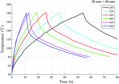 |
| | Fig. 6 Heating response of the graphene-based heater (40 mm × 40 mm) under various voltages within the range of 28 V to 48 V. | |
3.1.2 Maximum temperature of the graphene-based heater at various voltages. Fig. 7(a) shows the time-dependent temperature changes of the heater under relatively low voltages within the range of 10 V to 24 V. The heating response shown in Fig. 7(a) can be classified into two stages: the heating stage, and the maximum temperature stage. After heating for a period of time, the temperature reached a maximum and maintained constant over time. It can be seen in Fig. 7(b) that the maximum temperature increased quadratically with incrementation of the applied voltage. This is quite consistent with the Joule heating expression
where P is the total heating power of the graphene-based heater, R is the resistance of the heater and U is the applied voltage.
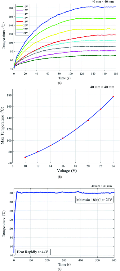 |
| | Fig. 7 Heating performance of the graphene-based heater (40 mm × 40 mm): (a) time-dependent temperature changes under various voltages within the range of 10 V to 24 V. (b) Maximum temperatures as a function of the voltage. (c) Rapid heating response and maximum temperature maintenance achieved by voltage adjustment. | |
3.1.3 Operational stability of the graphene-based heater. Both a rapid heating response and constant maximum temperature are required in the hot embossing process. To examine the operational stability of the graphene-based heater during the hot embossing process, the applied voltage was adjusted. A high voltage of 44 V was applied initially to raise the temperature of the 40 mm × 40 mm graphene-based heater quickly from 40 °C to 180 °C within 13 s. The voltage was then turned down to 24 V (refer to the Fig. 7(b)), allowing the temperature to remain at approximately 180 °C, as shown in Fig. 7(c). This experiment demonstrated the thermal stability of the graphene-based heater and the high bonding strength of the graphene–polymer composite enabling it to endure the temperature of 180 °C for a minimum time of ten minutes.
3.1.4 Heating rates of various graphene-based heaters differing in heating area. Fig. 8 shows the heating rates of various heaters differing in heating area under various input voltages. The heating rates increased as the applied voltage was increased. However, the heating rates decreased with an increase in heating area. At 40 V, for example, the heating rate of the 50 mm × 50 mm heater was merely 4.8 °C s−1, while the heating rate reached 14 °C s−1 with a heating area of 30 mm × 30 mm. These heating responses were recorded by infrared camera, as shown in the ESI in S3.† The results indicated that a higher voltage would be needed to fulfill the rapid heating requirement when using a larger heater.
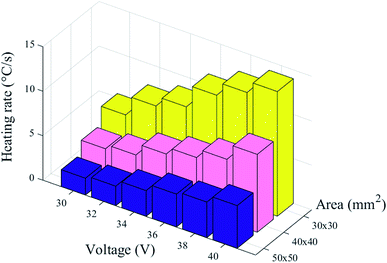 |
| | Fig. 8 Heating rates of various graphene-based heaters differing in heating area under various voltages within the range of 30 V to 40 V. | |
3.1.5 Heating repeatability of the graphene-based heater. Repeated heating and cooling cycles were conducted to evaluate the heating repeatability of the graphene-based heater. The temperature profiles are shown in Fig. 9. The electrical resistance of the graphene-based heater remained constant after 20 thermal cycles.
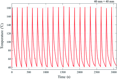 |
| | Fig. 9 Heating/cooling cycles of the graphene-based heater (40 mm × 40 mm) at 44 V. | |
3.2 Replication of microstructures embossed on polymeric substrates
3.2.1 Surface measurement. Surface scanning images and cross section profiles of the embossed microstructures were obtained by laser scanning confocal microscopy (LSCM). A microlens array embossed on a PC substrate is shown in Fig. 10. The average height of the replicated microlenses was 7.96 μm with a deviation of 0.04 μm (0.5%). A microcylinder array embossed on a PLA substrate is shown in Fig. 11. The average height of the replicated microcylinders was 2.81 μm with a deviation of 0.02 μm (0.7%). Fig. 12 shows an optical microscope image and a surface profile, measured with a Surface Profilometer, of a micro V-groove on a COP substrate. The average height of the V-groove was 23.76 μm with a deviation of 0.33 μm (1.4%). The small deviation showed that the three microstructures were successfully replicated onto different polymeric substrates by the rapid heating gas-assisted embossing process. Moreover, the total thermal cycle time of the embossing process was less than 30 s. Compared with the typical thermal cycle time of more than 10 min in the standard hot embossing process, a significant reduction in both thermal cycle time and energy wastage was achieved.
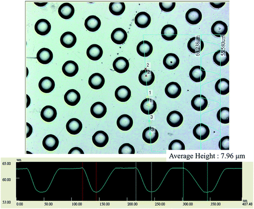 |
| | Fig. 10 Surface scanning and cross section profile of a microlens array on a PC substrate obtained by LSCM. | |
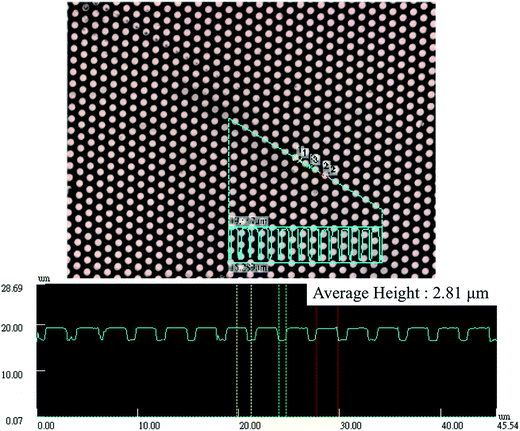 |
| | Fig. 11 Surface scanning and cross section profile of a micro cylinder array on a PLA substrate obtained by LSCM. | |
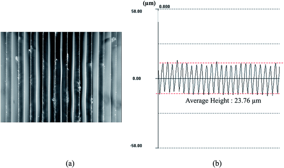 |
| | Fig. 12 V-groove pattern on a COP substrate: (a) image obtained by optical microscope. (b) Surface profile measured with surface profilometer. | |
3.2.2 Replication rate. To further verify the uniformity and consistency of the replications, the height of the three microstructures was measured at nine different points, located at the center of nine equally divided areas on 50 mm × 50 mm polymers. The replication rates were calculated, which was defined as the average height of microstructures on the polymer film divided by the average heights of microstructures on the tool, to prove the complete formation of the micropatterns. The results are shown in Table 3. The high consistency and uniformity of the replication, achieved via the uniformity of temperature provided by the graphene-based heating and the uniform embossing pressure exerted by gas, were verified for the three microstructures. Table 3 also shows that the average replication rates of the three microstructures on the polymers were all above 97%, demonstrating high precision in the replication of these microfeatures. The uniformity of the replication and overall quality of the microstructures illustrated the capability of the graphene–polymer composite heating gas-assisted embossing process.
Table 3 Replication rates (%) of the three embossed microstructures at the center of nine equally divided areas on the polymers
| Patterns |
Microlens array on PC |
Cylinder array on COP |
V groove on PLA |
| P1 |
99.8 |
∼100 |
97.4 |
| P2 |
99.4 |
99.2 |
97.5 |
| P3 |
98.6 |
∼100 |
97.9 |
| P4 |
∼100 |
99.1 |
99 |
| P5 |
99.5 |
∼100 |
97.6 |
| P6 |
98.9 |
93.2 |
97.6 |
| P7 |
∼100 |
99.6 |
97.4 |
| P8 |
99.2 |
96.9 |
98.2 |
| P9 |
97.9 |
99.7 |
97.9 |
| Avg. |
99.3 |
98.6 |
97.8 |
3.3 Replication of sub-microstructure
Our lab has fabricated a sub-microstructure by self-assembly technique, plasma scattering and reactive ion etching (RIE).18 Then utilizing the processing parameter of PC substrate, a sub-microstructure is replicated on PC with the embossing temperature of 170 °C and embossing pressure of 0.6 MPa. Fig. 13 shows the SEM image of the sub-microstructure on a PC substrate. The result shows the graphene–polymer composite heating gas-assisted embossing process cab be further used in replication for sub-microstructures.
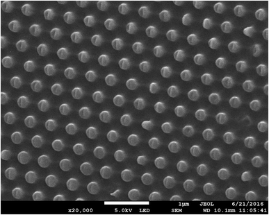 |
| | Fig. 13 SEM image of a sub-microstructure on a PC substrate. | |
4. Conclusion
In this study, a novel graphene–polymer composite heating gas-assisted embossing process was developed and implemented. A graphene-based heater was fabricated by dip coating a PI substrate with graphene conductive ink. The electrical resistance of the graphene-based heater was less than 50 Ω. Owing to the electrical and thermal conductivity of the graphene–polymer composite, the voltage of 28 V to 44 V were applied to achieve fast heating response. A maximum heating rate of 14 °C s−1 was achieved by applying a voltage of 44 V on a 30 mm × 30 mm graphene-based heater. A microlens array, a microcylinder array, and micro V grooves were successfully replicated on PC, PLA, and COP, respectively, with a forming area of 50 mm × 50 mm. The replication rates as measured at nine points demonstrated good uniformity of replication. The average replication rates of the three experiments were all above 97%, which shows that graphene–polymer composite heating is a way for the replication of microstructures by gas-assisted embossing. This study proved the great potential of the graphene–polymer composite heating gas-assisted embossing technique for replication of microstructures.
References
- C. Lu, Y.-J. Juang, L. J. Lee, D. Grewell and A. Benatar, Analysis of laser/IR-assisted microembossing, Polym. Eng. Sci., 2005, 45(5), 661–668 CAS
 .
. - C.-Y. Chang and C.-H. Yu, A basic experimental study of ultrasonic assisted hot embossing process for rapid fabrication of microlens arrays, J. Micromech. Microeng., 2015, 25(2), 25010 CrossRef CAS
 .
. - Y. Luo, X. Yan, N. Qi, X. Wang and L. Wang, Study of Double-Side Ultrasonic Embossing for Fabrication of Microstructures on Thermoplastic Polymer Substrates, PLoS One, 2013, 8(4), e61647 CAS
 .
. - P. Khuntontong, T. Blaser and W. K. Schomburg, Fabrication of Molded Interconnection Devices by Ultrasonic Hot Embossing on Thin Polymer Films, IEEE Trans. Electron. Packag. Manuf., 2009, 32(3), 152–156 CrossRef CAS
 .
. - W. K. Schomburg, K. Burlage and C. Gerhardy, Ultrasonic Hot Embossing, Micromachines, 2011, 2(2), 157–166 CrossRef
 .
. - S.-K. Hong, Y.-M. Heo and J. J. Kang, in Replication of polymeric micro patterns by rapid thermal pressing with induction heating apparatus, 3rd IEEE International Conference on Nano/Micro Engineered and Molecular Systems, Sanya, 2008, pp. 911–915 Search PubMed
 .
. - P. Xie, P. He, Y.-C. Yen, K. J. Kwak, D. Gallego-Perez and L. Chang, et al., Rapid hot embossing of polymer microstructures using carbide-bonded graphene coating on silicon stampers, Surf. Coat. Technol., 2014, 258, 174–180 CrossRef CAS
 .
. - J. Liang, Y. Wang, Y. Huang, Y. Ma, Z. Liu and J. Cai, et al., Electromagnetic interference shielding of graphene/epoxy composites, Carbon, 2009, 47(3), 922–925 CrossRef CAS
 .
. - Y. G. Jeong and J.-E. An, UV-cured epoxy/graphene nanocomposite films: preparation, structure and electric heating performance, Polym. Int., 2014, 63(11), 1895–1901 CrossRef CAS
 .
. - J.-E. An and Y. G. Jeong, Structure and electric heating performance of graphene/epoxy composite films, Eur. Polym. J., 2013, 49(6), 1322–1330 CrossRef CAS
 .
. - K. S. Choi, F. Liu, J. S. Choi and T. S. Seo, Fabrication of Free-Standing Multilayered Graphene and Poly(3,4-ethylenedioxythiophene) Composite Films with Enhanced Conductive and Mechanical Properties, Langmuir, 2010, 26(15), 12902–12908 CrossRef CAS PubMed
 .
. - S. Stankovich, D. A. Dikin, G. H. B. Dommett, K. M. Kohlhaas, E. J. Zimney and E. A. Stach, et al., Graphene-based composite materials, Nature, 2006, 442(7100), 282–286 CrossRef CAS PubMed
 .
. - I.-H. Kim and Y. G. Jeong, Polylactide/exfoliated graphite nanocomposites with enhanced thermal stability, mechanical modulus, and electrical conductivity, J. Polym. Sci., Part B: Polym. Phys., 2010, 48(8), 850–858 CrossRef CAS
 .
. - J. Kang, H. Kim, K. S. Kim, S.-K. Lee, S. Bae and J.-H. Ahn, et al., High-Performance Graphene-Based Transparent Flexible Heaters, Nano Lett., 2011, 11(12), 5154–5158 CrossRef CAS PubMed
 .
. - Z. Song, T. Xu, M. L. Gordin, Y.-B. Jiang, I.-T. Bae and Q. Xiao, et al., Polymer–Graphene Nanocomposites as Ultrafast-Charge and Discharge Cathodes for Rechargeable Lithium Batteries, Nano Lett., 2012, 12(5), 2205–2211 CrossRef CAS PubMed
 .
. - H. Gao, H. Tan, W. Zhang, K. Morton and S. Y. Chou, Air cushion press for excellent uniformity, high yield, and fast nanoimprint across a 100 mm field, Nano Lett., 2006, 6(11), 2438–2441 CrossRef CAS PubMed
 .
. - H. Hiroshima and M. Komuro, UV-nanoimprint with the assistance of gas condensation at atmospheric environmental pressure, J. Vac. Sci. Technol., B: Microelectron. Nanometer Struct.--Process., Meas., Phenom., 2007, 25(6), 2333–2336 CrossRef CAS
 .
. - R. H. Hong, C. Cheng, T. C. Shu and S. Y. Yang, Fabrication and Application of Nanostructures Using Gas-Assisted Hot Embossing and Self-Assembled Nanospheres, Key Eng. Mater., 2015, 659, 399–403 CrossRef
 .
.
Footnote |
| † Electronic supplementary information (ESI) available. See DOI: 10.1039/c6ra27618k |
|
| This journal is © The Royal Society of Chemistry 2017 |
Click here to see how this site uses Cookies. View our privacy policy here.  Open Access Article


.
.
.
.
.
.
.
.
.
.
.
.
.
.
.
.
.
.


