 Open Access Article
Creative Commons Attribution 3.0 Unported Licence
Graphene/cellulose nanocrystals hybrid aerogel with tunable mechanical strength and hydrophilicity fabricated by ambient pressure drying technique†
Xiaofang Zhang,
Ping Liu,
Yongxin Duan,
Min Jiang * and
Jianming Zhang*
Key Laboratory of Rubber-Plastics, Ministry of Education/Shandong Provincial Key Laboratory of Rubber-Plastics, Qingdao University of Science & Technology, Qingdao City 266042, People's Republic of China. E-mail: zjm@qust.edu.cn; jiangmin@qust.edu.cn
First published on 15th March 2017
Abstract
Ultralight graphene/cellulose nanocrystal (CNC) hybrid aerogels (GCHAs) were prepared via an integration strategy of a two-step reduction process and ambient drying technology. Such a preparation strategy causes the as-prepared GCHAs to circumvent an issue of structural collapse induced by shrinkage in an ordinary ambient drying process. GCHAs have three-dimensional large cellular structures with CNC-sandwiched graphene flakes. Incorporation of stiff rod-like CNCs in a flexible graphene aerogel (GA) with hydrophobicity realized the multifunction of hybrid GA materials. With the increase of CNCs loading, the modulus of GCHAs enhanced obviously. The mechanical strength of GCHAs could be controlled by adjusting the CNC loading. The sorption experiments of both organic solvents and water on the GCHAs were carried out and GCHAs presented good amphiphilic absorption capacity. The work provides a promising amphiphilic graphene-based aerogel material with tunable mechanical strength by a facile, economic and environmentally-friendly approach, giving it high potential for use in waste water treatment and pressure sensitive materials.
1 Introduction
As an emerging material, the three-dimensional self-assembled graphene aerogel (GA) has attracted much attention from both academia and industry. Owing to its ultralight character, high compressibility, high porosity, high surface area and excellent electrical properties, GA has shown tremendous potential in energy dissipation,1–4 conductive sensors,5–9 catalyst supports10–15 and recyclable absorbents.16–24 In order to meet the various requirements, hybrid GA materials with other additives have been designed and prepared. For example, Feng et al.11 prepared a graphene/Fe3O4 aerogel electrocatalyst by loading Fe3O4 nanoparticles into GA uniformly, which showed better electrocatalytic behavior for oxygen reduction reaction than a pure Fe3O4 nanoparticle electrocatalyst. Wu et al.10 investigated the in situ growth of V2O5 nanofibers on graphene sheets by coordination effect and obtained a hierarchical porous V2O5/graphene hybrid aerogel for supercapacitors. Benefiting from the large surface area of graphene, SnO2 nanocrystals could deposit on graphene sheets without agglomeration to produce the SnO2/graphene hybrid foam with excellent sensing gas performance for NO2.25 Besides composite of graphene and metallic oxide nano-particle, the graphene/polymer composites also draw researchers' attention. Zhang et al.26 reported mechanically robust graphene/polydimethylsiloxane hybrid aerogels with multi-functional properties, including high electrical conductivity, thermal conductivity and outstanding mechanical performance.Additionally, GA and hybrid GA materials showed many outstanding performances as absorbent materials in water treatment. Gao's group21 developed an assembly strategy to fabricate ultra-light graphene/CNT aerogels with controlled densities. Their extremely low densities and extremely high absorption capacities for organic liquids originated from synergistic effect between elastic CNT ribs and giant graphene cell walls. Nevertheless, the super hydrophobic feature also limits their application in treating hydrophilic substance. Recently, amphiphilic graphene aerogel aroused scientists' interests, owing to their potential applications in industrial waste waters. Yao et al.20 prepared an amphiphilic graphene-based aerogel by incorporating hydrophilic nanofibrillated cellulose to reduced graphene oxide. Such amphiphilic aerogels showed excellent absorption for both organic solvents and water. However, an additive of aluminum nitrate nonahydrate as crosslinking agent was used in their work which caused the randomly organized structure and negative unloading stress. Moreover, in the above-mentioned works, freeze drying or subcritical point drying techniques were the main strategies for the fabrication of GA and hybrid aerogels. These drying techniques required specific equipment with high cost and energy consumption,27 and as-prepared GA exhibited large volume shrinkage in contrast to the wet gel. Therefore, we made use of an ambient pressure drying way to prepare graphene aerogel materials with superelasticity by careful controlling the reduction degree of GO and selecting general freezing conditions.18 This improved technique could be widely applied in the fabrication of the hybrid graphene aerogel materials with less shrinkage.
Herein, we fabricated ultra-light, multifunctional graphene/cellulose nanocrystals (CNCs) hybrid aerogels (GCHAs) by ambient pressure drying technique. CNCs, derived from cotton and wood by strong acid hydrolysis, are high aspect ratio rod-like particles with nanoscale dimensions. CNCs have attracted considerable interest due to their high mechanical properties, sustainability and availability for functional applications.28–30 And the rich hydroxyl groups of CNCs endow themselves water-wet behavior.31 Incorporation of stiff rod-like CNCs in flexible GA with hydrophobicity can realize multifunction of hybrid GA aerogel material. The resulting GCHAs materials exhibited tunable mechanical strength and hydrophilic property by controlling the CNCs loading. The absorption capacity of water and other organic liquids on the GCHAs was also investigated.
2 Experimental
2.1 Materials
Graphite flakes (80 μm) was provided by Qingdao Xinghua Graphite Product Co., Ltd. (China). Cotton linter pulp was supplied by Hubei Chemical Fiber Co., Ltd. (China). L-Ascorbic acid, sulfuric acid (98%), sodium hydroxide, potassium permanganate, hydrogen peroxide (37%) were purchased from Sinopharm chemical reagent Co., Ltd. (China) and used as received.2.2 Synthesis of CNCs
CNCs were prepared by a modified sulfuric acid hydrolysis of cotton linter pulp, which was reported in our previous paper.41 Finally, ivory-white suspension was obtained (the inset in Fig. S1, ESI†). And its zeta potential was −35 mV which indicated that it was stable aqueous dispersion. Atomic force microscope (AFM) picture (Fig. S1, ESI†) shows that the CNCs present rod-like shape with the diameter of about 8 nm.2.3 Fabrication of GCHAs
Graphene oxide (GO) was prepared via a modified Hummer's method, using natural graphite with a particle size of 180 meshes as raw material.18 The 5 mg mL−1 GO aqueous dispersion and CNCs aqueous dispersion with different concentrations (0.15 mg mL−1, 0.79 mg mL−1, 1.67 mg mL−1, 3.75 mg mL−1 and 15 mg mL−1) were configured for further assembly. In a typical procedure for fabricating GA and GCHAs, 6 mL GO aqueous dispersion, 2 mL CNCs aqueous dispersion and 60 mg L-ascorbic acid were mixed uniformly via magnetic stirring. The composite suspensions were transferred and sealed into a cylindrical glass bottle, and then the bottle was placed in a 95 °C oven. Thirty minutes later, graphene/CNCs hybrid hydrogel took shape in which GO was partially reduced (C/O = 1.69). Subsequently, the hydrogel was cooled down to room temperature and frozen in a refrigerator (−15 °C) for 4 hours. The frozen hydrogel was then thawed at room temperature and underwent further reduction (95 °C, in the air dry oven) for 5 hours to obtain fully reduced GO hybrid hydrogel (C/O = 5.04). The as-prepared hydrogel pillar was repeatedly rinsed with deionized water as well as ethanol and dried in an ordinary oven at 65 °C for 24 hours to generate GCHA-X materials (where X denotes the weight content of CNCs in hybrid aerogels).2.4 Characterization
Densities were measured through the masses of GCHAs monoliths divided by their volumes. XRD diffraction patterns were collected on a Rigaku Ultima IV diffractometer equipped with Cu Kα radiation (λ = 0.154 nm) at room temperature. Scanning electron microscopy (SEM) images were obtained using a field emission SEM (JSM-7500F) at an accelerating voltage of 5 kV. Atomic force microscope (AFM) images in Fig. S1 and S5 (ESI†) were acquired via a Multimode 8 Bruker microscope with a silicon cantilever using the scanasyst mode. Samples corresponded to Fig. S1 and S2† were casted and spin-coated respectively on freshly cleaved mica sheets at 2000 rpm. The compressive tests were performed on a dynamic mechanical analysis (DMA) (TA, Q800) with a strain rate of 5% per second at room temperature. Water contact angle measurements were executed on JC2000D2 contact goniometer (Shanghai Zhongchen digital technology apparatus company). The pictures were obtained at 5 seconds after water-drops dropped on GA and GCHAs surface.3 Results and discussion
3.1 Fabrication of GCHAs materials by ambient pressure drying technique
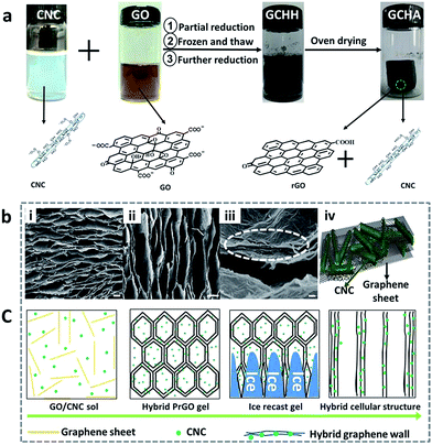
The preparing procedure of GCHAs is illustrated in Fig. 1a. At first, a stable suspension containing rod-like CNCs and flake-like GO was obtained by simple liquid blending. Due to the negatively charged sulfate ester groups on the surfaces, the employed CNCs with typical size of about 8 nm in width and 200 nm in length can be dispersed in water to form stably aqueous suspensions (see the insert picture in Fig. S1, ESI†). Likewise, GO sheets can form stable suspensions due to the negative charges on their surfaces in the pH range of 2–8.32 When two suspensions were mixed together, a homogeneous blending dispersion was obtained for further preparation of hybrid aerogels. A two-step reduction strategy was adopted to prepare GCHAs. Firstly, the aforementioned mixed suspensions underwent a thirty-minutes heating to produce an intermediate product. GO sheets were partially reduced GO (PrGO) by L-ascorbic acid. The obtained intermediate product was then completely frozen at −15 °C. It is noted that a decrease in cooling rate during freezing is a very effective path to minimize the capillary force so that as-prepared aerogels with very little shrinkage can be obtained via subsequently ambient pressure drying route.18 Secondly, the frozen sample was thawed and reheated until a completely reduced graphene hybrid hydrogel (GCHH) formed. In the last step, the graphene/CNCs hybrid hydrogels were dried in an oven to produce GCHAs. The GCHAs could keep the original shape of hydrogel well with less volume shrinkage.SEM images of GCHA-20 were shown in Fig. 1i–iii, as a representative sample. Similar to the typical structure of GA reported in literatures,1,3,18 the fractured cross section of GCHA-20 presented honeycomb-like cellular structure (Fig. 1i), although 20 wt% CNCs was added into the system. SEM image of GCHA-20 from vertical section (Fig. 1ii) shows plumb channels induced by ice recast gel. When graphene sheets were broken, some rod-like CNCs was found at the breaking edge in Fig. 1iii, which indicated that some CNCs were sandwiched33 between graphene flakes (as depicted in Fig. 1iv). Moreover, some CNCs aggregates seemed to be on the pleated surface of graphene nanosheets walls. High-resolution transmission electron microscope (HRTEM) is the visual and powerful tool to observe internal structure of materials. From Fig. S2,† it is clearly seen that inner structure of GCHA-50 is quite disorder, which is much different from pure GA with regular lamellar structure. It is speculated that the existence of CNCs hinders graphene sheets to regularly organize together. And the space between two graphene sheets is about 0.4 nm in the enlargement image of Fig. S2,† which is smaller than that of GO (0.89 nm that of pure GA).18 It results from the decrease of oxygen-containing functional groups on GO sheets during reduction process and the further improved π–π interactions between graphene sheets.18,34 In addition, CNCs were found to be uniformly distributed over graphene nanosheets from Fig. S3.† Fig. 1c presents the formation process of the cellular structure of GCHAs from left to right. At the beginning, CNCs and GO could stably disperse in water and formed a homogeneous system. The following freeze-recast procedure forced CNCs to be compressed into the space between graphene sheets with the help of the growing columnar or lamellar ice.1,3,35–37 In the last solvent evaporation step, the compressed CNCs still kept the close contact with GO nanosheets and the stable free-standing 3D GCHAs were obtained.
In order to further understand interaction between two species, the following experiments were operated as shown in Fig. S4.† When the mixing GO/CNCs dispersion was partly reduced, a hydrogel system was presented. Taking out of the hydrogel from the vessel, the residual liquid (liquid-A in Fig. S4, ESI†) was characterized by AFM. No trace of rod-like CNCs and GO nanosheets could be detected (AFM images were not provided here). Therefore, we can consider that CNCs were encapsulated completely in graphene hydrogel network and all GO nanosheets took part in the construction of hydrogel network. If the top of the partially reduced hybrid hydrogel was pressed by force, some liquid (liquid-B in Fig. S4, ESI†) was squeezed out of hydrogel. By AFM measurement, rod-like CNCs and 2D partially reduced GO flakes can be found in liquid-B, as shown in Fig. S5.† It meant that CNCs aggregates were adsorbed on the graphene sheets besides free CNCs. Although CNCs were incorporated into hydrogel network, some free CNCs were still removed from the inner of hydrogel by external pressure due to the repel interaction with GO. As for partially reduced GO, the mutual attraction with CNCs was improved so that more CNCs absorbed on the graphene sheets. Therefore, the construction of the final aerogel were stable and CNCs were sandwiched in graphene flakes as soon as GO were completely reduced to graphene.
3.2 Effect of CNCs loading on the morphology and structure of GCHAs
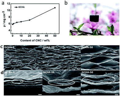
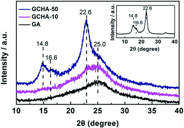
Density is an important parameter for aerogel materials. The addition of CNCs must cause an increase in the density of GA. Fig. 2a shows the plot of the density of GCHAs versus the contents of CNCs in GCHAs. When the content of CNCs increases from 1 wt% to 50 wt%, the density of GCHAs also increases from 5.8 to 10.8 mg cm−3. Notably, the density of GCHA-50 is so close to that of ultra-light graphene aerogel (<10 mg cm−3)21,38 that it can easily stand on the pistil (as shown in Fig. 2b). The GCHAs still show a high porosity (99.6%) which is comparable with GA. In order to investigate the influence of CNCs loading on the structure of GCHAs, SEM images of GCHAs with 5 wt%, 20 wt% and 50 wt% of CNCs were exhibited in Fig. 2c. All the GCHAs own the cork-like hierarchical porous structure and the pore sizes are relatively uniform. These pores in GCHAs are bigger than that of pure GA materials fabricated by freeze drying or subcritical point drying techniques.1,3,17,20,21 It can be ascribed to the smaller temperature gradient in the domestic refrigerator that promotes the formation of bigger ice block and corresponding larger pores.39,40 When more CNCs were loaded to the GA, the pores became large even to millimeter level. The possible reason is that more hydrophilic CNCs benefit the contact of water with them and lead to the formation of bigger ice block during the freezing process. Fig. 2d shows the fracture morphology of the corresponding GCHAs in Fig. 2c. From the marked circle part, the rod-like CNCs can be easily discriminated at the fracture edge of GCHAs. As for GCHA-50 sample, more CNCs appear clearly in contrast to GCHA-10 and GCHA-20 sample. Such the hybrid structure containing CNCs among graphene sheets offers GCHAs materials with an improved mechanical strength to resist external loadings.It is well-known that GO presents a strong XRD diffraction peak at 9–10° corresponding to an interlayer space of 0.89 nm. When GO is reduced, the removal of oxygen-containing functional groups results in the enhanced π–π interactions between graphene sheets. So the interlayer space decreases with a large shift of the diffraction peak to 25° in XRD pattern18,34 (see the curve for GA in the Fig. 3). In addition, CNCs exhibit obvious diffraction peaks in XRD pattern (Fig. 3). The loaded CNCs with enough amounts can make its characteristic peaks to be recognized. When 10 wt% CNCs were loaded in GCHA-10, a peak at 22.6° seems appear (see the curve for GA). As for GCHA-50, three peaks at 14.8°, 16.6° and 22.6° for CNCs41,42 and one broad peak at 25° for graphene were observed. It demonstrates that the original crystal structure of CNCs do not change through 6 h-heating treatment at 95 °C (see experimental section) and they succeed to be loaded into GA 3D network.
3.3 Tunable mechanical strength of GCHAs
Fig. 4 shows the photographs of qualitative compressive tests of GA and GCHAs with 100 g-weights on their tops. It is clearly observed that the deformation degree of GCHAs is distinct. GA shows the best compressibility, while GCHA-50 with the highest content of CNCs is so stiff as to display a little deformation. This phenomenon was attributed to the existence of rod-like, high modulus CNCs nanomaterial.28,30 CNCs-sandwiched structure between graphene flakes could enhance the compression strength of 3D aerogel and further hinder the deformation under external force.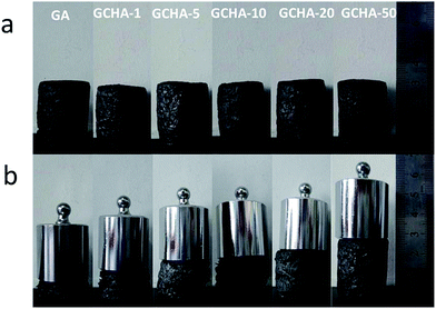 | ||
| Fig. 4 Pictures of compressive tests of GA and GCHAs for demonstrating the variation of compressive strength with CNCs content changing. The employed weights are 100 g for all samples. | ||
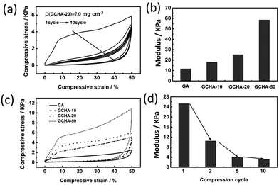
The stress–strain curves of the GCHAs are presented in Fig. 5. All compressive tests were conducted along the axial direction of regular cylindrical sample due to a high degree of order. As shown in Fig. 5a, four samples (GA, GCHA-10, GCHA-20 and GCHA-50) display the regular compression curves for the first cycle up to 50% strain, in which the stress enhances gradually with the increasing strain. And it should be noticed that more CNCs loaded in GA result in the larger stress at the same strain, which is consistent with the qualitative compressive tests (Fig. 4). When 50 wt% CNCs were loaded, the stress at 50% strain could reach 11 kPa which is higher than graphene/carbon nanotubes aerogel (6 kPa),21 graphene/nanofibrillated cellulose aerogel (5 kPa)20 and other pure GA (8 kPa).18 This result can be explained from two viewpoints. On one hand, the rod-like CNC has the higher modulus than the linear carbon nanotubes and flexible nanofibrillated cellulose. On the other hand, cellular structure along vertical direction caused by ice crystals thawing in our experimental strategy could offer further support to resist deformation of GCHAs.1,3,17,35 Furthermore, the recovery behavior of the compressed GCHAs is good (Fig. S6, ESI†). Such a compression recovery property affords GCHAs materials opportunity for reuse, and maybe some potential application in pressure sensor.
All the curves in Fig. 5a show three characteristic deformation regions, which are similar to those observed in open-cell aerogels.35 The strain–stress curve below 7% strain presents linear changes reflecting the elastic bending of the GCHA walls. Elastic bucking of the cell walls is observed with the appearance of plateau when the strain is between 7% and 35% for GCHA-50. Especially, the plateau length of GCHA-50 curves is longer than that of GCHA-20 and GCHA-10. It means that the GCHAs with more CNCs loading are easily compressed to densification. And the third character is densification regime. Modulus values of the GA and GCHAs are diagrammed in Fig. 5b according to the strains below 7%. High-content CNCs sandwiched between graphene flakes can afford the GCHAs with a high modulus.43 In other words, the modulus of GCHAs is tunable by adjusting the CNCs loading. In order to investigate the reusability of the GCHAs, the cycling compress-recovery curves of GCHA-20 were measured. As shown in Fig. 5c, the first compression cycle is different from the subsequent ones. It shows the higher modulus, maximum stress and larger loss coefficient. In contrast, the second cycle shows much contraction, moreover, the hysteresis loops exhibit a little change in the following eight cycles. Fig. 5d displays that the modulus of GCHA-20 decreases with an increase of compression cycles. It demonstrates that the compressibility of GCHA-20 tends to be stable after the resistance from CNCs disappears during the first compression cycle. Most compression curves of the hybrid graphene aerogels show the similar changes.1,3,17,18,21
3.4 Tunable amphiphilic property of GCHAs
It has been reported that GA is an ideal candidate for the sorption of organic pollutants and oils.17–22 When hydrophilic CNCs was loaded into GA materials, the hybrid GCHAs were expected to act as amphiphilic materials applied in water-treatment fields. Hydrophilic behavior of GCHAs is the primary property to be investigated. Fig. 6 shows the sorption behavior of GA and GCHAs towards pure water taken at different soaking periods. At the beginning, the aerogels were put onto the air/water interface gently. Because of their ultralight feature, both GA and GCHAs floated on the water surface. GCHA-50 began to sink in two seconds, while GCHA-20 tended to sink in ten seconds. After 240 s floating, GCHA-5 was nearly soaked under the water surface. However, GA and GCHA-1 still floated on the water surface presenting strong hydrophobicity. When the content of hydrophilic CNCs in GA is high enough (e.g. 50 wt%), GCHAs materials show the hydrophilic behavior instantly. When the content of CNCs in GA is between 5 wt% and 20 wt%, it will take sandwiched-CNCs times to contact with water. As a result, the corresponding GCHAs materials present moderate hydrophilicity. Contact angle measurement is an important tool to characterize the wettability of solids. As shown in Fig. S7,† the contact angle of water on GA is 78°, while the value for GCHA-50 is 0°. These results manifest that GCHAs with higher CNCs loading possess better hydrophilicity. Those hybrid materials will enrich applications of GA for different requirements.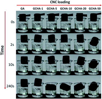 | ||
| Fig. 6 Photographs showing the differences in water sorption capacity of GA and GCHAs at different soakage durations. | ||
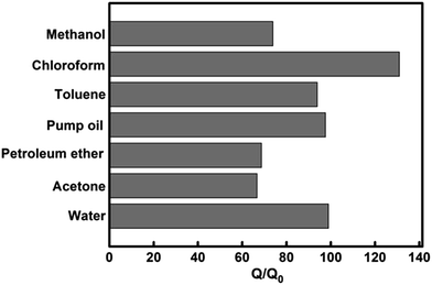
In order to study amphiphilic property of GCHA-20, some common organic pollutants were chosen as absorbates (Fig. 7) besides water. The GCHA-20 materials can absorb chloroform up to 130 times of its own weight, and absorb toluene, pump oil and water up to 100 times of its own weight. As for methanol, petroleum ether and acetone, the absorption quantities are nearly 70 times of the weight of GCHA-20. Though 20 wt% CNCs (the absolute content was 14.8 wt% in the dried GCHA-20) are loaded which is less than the loading content of hydrophilic NFC in GA,20 GCHA-20 shows better absorptive capacity for water than NFC/GA materials, and also for petroleum ether. More importantly, the employed ambient pressure drying technique is more simple, energy-saving and easy approach to realize industrialization.
4 Conclusions
In summary, we have fabricated graphene-based hybrid aerogel materials with tunable mechanical strength and hydrophilicity. Negatively charged CNCs and GO aqueous suspension were acted as precursor to be further self-assembled by two-step reduction strategy and ambient drying technology. Three-dimensional large cellular structure afforded as-prepared GCHAs materials with ultra-light and compressible property. And the CNCs-sandwiched graphene flakes structure can enhance the mechanical strength of GCHAs to defend the external force. The mechanical strength of GCHAs could be controlled by adjusting the CNC loading. With the help of excellent hydrophilicity of CNCs, GCHA containing 20 wt% CNCs can adsorb water up to 100 times of its own weight despite GA component showing strong hydrophobicity. The work provides a promising amphiphilic graphene-based aerogel material with tunable mechanical strength by a facile, economical and environmental-friendly approach, making it highly potential in waste water treatment and pressure sensitive materials.Acknowledgements
The work was funded by Taishan Mountain Scholar Constructive Engineering Foundation (TS20081120 and tshw20110510) and Shandong Provincial Natural Science Foundation of China (No. ZR2015BM027).Notes and references
- L. Qiu, J. Z. Liu, S. L. Chang, Y. Wu and D. Li, Nat. Commun., 2012, 3, 1241 CrossRef PubMed.
- Y. Li, J. Chen, L. Huang, C. Li, J. D. Hong and G. Shi, Adv. Mater., 2014, 26, 4789–4793 CrossRef CAS PubMed.
- H. L. Gao, Y. B. Zhu, L. B. Mao, F. C. Wang, X. S. Luo, Y. Y. Liu, Y. Lu, Z. Pan, J. Ge, W. Shen, Y. R. Zheng, L. Xu, L. J. Wang, W. H. Xu, H. A. Wu and S. H. Yu, Nat. Commun., 2016, 7, 12920 CrossRef CAS PubMed.
- Y. Wu, N. Yi, L. Huang, T. Zhang, S. Fang, H. Chang, N. Li, J. Oh, J. A. Lee, M. Kozlov, A. C. Chipara, H. Terrones, P. Xiao, G. Long, Y. Huang, F. Zhang, L. Zhang, X. Lepro, C. Haines, M. D. Lima, N. P. Lopez, L. P. Rajukumar, A. L. Elias, S. Feng, S. J. Kim, N. T. Narayanan, P. M. Ajayan, M. Terrones, A. Aliev, P. Chu, Z. Zhang, R. H. Baughman and Y. Chen, Nat. Commun., 2015, 6, 6141 CrossRef CAS PubMed.
- Z. Chen, W. Ren, L. Gao, B. Liu, S. Pei and H. M. Cheng, Nat. Mater., 2011, 10, 424–428 CrossRef CAS PubMed.
- S. Barg, F. M. Perez, N. Ni, P. do Vale Pereira, R. C. Maher, E. Garcia-Tunon, S. Eslava, S. Agnoli, C. Mattevi and E. Saiz, Nat. Commun., 2014, 5, 4328 CAS.
- X. Zhang, Z. Sui, B. Xu, S. Yue, Y. Luo, W. Zhan and B. Liu, J. Mater. Chem., 2011, 21, 6494–6497 RSC.
- L. Zhang, F. Zhang, X. Yang, G. Long, Y. Wu, T. Zhang, K. Leng, Y. Huang, Y. Ma, A. Yu and Y. Chen, Sci. Rep., 2013, 3, 1408–1416 Search PubMed.
- G. Tang, Z.-G. Jiang, X. Li, H.-B. Zhang, A. Dasari and Z.-Z. Yu, Carbon, 2014, 77, 592–599 CrossRef CAS.
- Y. Wu, G. Gao and G. Wu, J. Mater. Chem. A, 2015, 3, 1828–1832 CAS.
- Z. S. Wu, S. Yang, Y. Sun, K. Parvez, X. Feng and K. Mullen, J. Am. Chem. Soc., 2012, 134, 9082–9085 CrossRef CAS PubMed.
- L. Chen, B. Wei, X. Zhang and C. Li, Small, 2013, 9, 2331–2340 CrossRef CAS PubMed.
- B. Qiu, M. Xing and J. Zhang, J. Am. Chem. Soc., 2014, 136, 5852–5855 CrossRef CAS PubMed.
- X. Cui, S. Yang, X. Yan, J. Leng, S. Shuang, P. M. Ajayan and Z. Zhang, Adv. Funct. Mater., 2016, 26, 5708–5717 CrossRef CAS.
- L. Chen, R. Du, J. Zhu, Y. Mao, C. Xue, N. Zhang, Y. Hou, J. Zhang and T. Yi, Small, 2015, 11, 1423–1429 CrossRef CAS PubMed.
- Z. Ma, D. Liu, Y. Zhu, Z. Li, Z. Li, H. Tian and H. Liu, Carbohydr. Polym., 2016, 144, 230–237 CrossRef CAS PubMed.
- T. Liu, M. Huang, X. Li, C. Wang, C.-X. Gui and Z.-Z. Yu, Carbon, 2016, 100, 456–464 CrossRef CAS.
- H. Yang, T. Zhang, M. Jiang, Y. Duan and J. Zhang, J. Mater. Chem. A, 2015, 3, 19268–19272 CAS.
- R. Zhang, Y. Cao, P. Li, X. Zang, P. Sun, K. Wang, M. Zhong, J. Wei, D. Wu, F. Kang and H. Zhu, Nano Res., 2014, 7, 1477–1487 CrossRef CAS.
- X. Yao, W. Yu, X. Xu, F. Chen and Q. Fu, Nanoscale, 2015, 7, 3959–3964 RSC.
- H. Sun, Z. Xu and C. Gao, Adv. Mater., 2013, 25, 2554–2560 CrossRef CAS PubMed.
- S. Kabiri, D. N. H. Tran, T. Altalhi and D. Losic, Carbon, 2014, 80, 523–533 CrossRef CAS.
- V. Chandra, J. Park, Y. Chun, J. W. Lee, I. C. Hwang and K. S. Kim, ACS Nano, 2010, 4, 3979–3986 CrossRef CAS PubMed.
- J. Li, J. Li, H. Meng, S. Xie, B. Zhang, L. Li, H. Ma, J. Zhang and M. Yu, J. Mater. Chem. A, 2014, 2, 2934–2941 CAS.
- L. Li, S. He, M. Liu, C. Zhang and W. Chen, Anal. Chem., 2015, 87, 1638–1945 CrossRef CAS PubMed.
- Q. Zhang, X. Xu, H. Li, G. Xiong, H. Hu and T. S. Fisher, Carbon, 2015, 93, 659–670 CrossRef CAS.
- D. Wu, R. Fu, S. Zhang, M. S. Dresselhaus and G. Dresselhaus, Carbon, 2004, 42, 2033–2039 CrossRef CAS.
- R. J. Moon, A. Martini, J. Nairn, J. Simonsen and J. Youngblood, Chem. Soc. Rev., 2011, 40, 3941–3994 RSC.
- M. D. Xue, J. Revol and D. G. Gray, Cellulose, 1998, 5, 19–32 CrossRef.
- Y. Habibi, L. A. Lucia and O. J. Rojas, Chem. Rev., 2010, 110, 3479–3500 CrossRef CAS PubMed.
- A. Isogai, T. Saito and H. Fukuzumi, Nanoscale, 2011, 3, 71–85 RSC.
- C. Li, J. Adamcik and R. Mezzenga, Nat. Nanotechnol., 2012, 7, 421–427 CrossRef CAS PubMed.
- Y.-S. Ye, H.-X. Zeng, J. Wu, L.-Y. Dong, J.-T. Zhu, Z.-G. Xue, X.-P. Zhou, X.-L. Xie and Y.-W. Mai, Green Chem., 2016, 18, 1674–1683 RSC.
- W. Chen and L. Yan, Nanoscale, 2011, 3, 3132–3137 RSC.
- J. Kuang, Z. Dai, L. Liu, Z. Yang, M. Jin and Z. Zhang, Nanoscale, 2015, 7, 9252–9260 RSC.
- H. Zhang, I. Hussain, M. Brust, M. F. Butler, S. P. Rannard and A. I. Cooper, Nat. Mater., 2005, 4, 787–793 CrossRef CAS PubMed.
- S. Deville, E. Saiz, R. K. Nalla and A. P. Tomsia, Science, 2006, 311, 515–518 CrossRef CAS PubMed.
- T. A. Schaedler, A. J. Jacobsen, A. Torrents, A. E. Sorensen, J. Lian, J. R. Greer, L. Valdevit and W. B. Carter, Science, 2011, 334, 962–965 CrossRef CAS PubMed.
- B. Wicklein, A. Kocjan, G. Salazar-Alvarez, F. Carosio, G. Camino, M. Antonietti and L. Bergstrom, Nat. Nanotechnol., 2015, 10, 277–283 CrossRef CAS PubMed.
- X. Xie, Y. Zhou, H. Bi, K. Yin, S. Wan and L. Sun, Sci. Rep., 2013, 3, 2117–2122 Search PubMed.
- Q. Chen, P. Liu, F. Nan, L. Zhou and J. Zhang, Biomacromolecules, 2014, 15, 4343–4350 CrossRef CAS PubMed.
- K. K. Sadasivuni, A. Kafy, L. Zhai, H. U. Ko, S. Mun and J. Kim, Small, 2015, 11, 994–1002 CrossRef CAS PubMed.
- R. Xiong, K. Hu, A. M. Grant, R. Ma, W. Xu, C. Lu, X. Zhang and V. V. Tsukruk, Adv. Mater., 2016, 28, 1501–1509 CrossRef CAS PubMed.
Footnote |
| † Electronic supplementary information (ESI) available. See DOI: 10.1039/c6ra28178h |
| This journal is © The Royal Society of Chemistry 2017 |

