 Open Access Article
Preparation, characterization and tribological mechanism of nanofluids
Linghui Kong
 ,
Jianlin Sun
* and
Yueyue Bao
School of Materials Science and Engineering, University of Science and Technology Beijing, Beijing 100083, P. R. China. E-mail: sjl@ustb.edu.cn; Tel: +86 1062333768
First published on 22nd February 2017
Abstract
A nanofluid is a dispersion of nanoparticles in a base fluid and it has been a hot topic of great interest in recent years primarily due to its potential application in various fields. This review presents an overview of the remarkable progress on nanofluids during the past two decades. Nanoparticles have been investigated intensively as an additive for lubricants due to their special tribological properties. This article is focused on various synthetic methods and characterization techniques of nanofluids. Factors enhancing the stability and lubrication mechanism have been delineated in detail. Although nanofluids are potential candidates for tribological applications, there are still many challenges to overcome. These challenges involve the long term stability of nanofluids and validation of lubrication mechanisms. Especially, nanofluid stability and high costs of production are obstacles for the application of nanofluids. The current review also discusses the problems of nanofluids applied in lubrication.
1 Introduction
Advanced lubricants can improve productivity through energy saving and prolonging the life cycle of machinery. “Nanofluids” was coined by Choi in 1995. Since then, nanofluids have been studied in many fields, including the chemical industry, biomedical applications, electronics cooling, environment engineering and waste heat recovery. And this situation is also true in the tribology. Studies have shown that the dispersion of small amounts of nano-scale solid particles in base fluids, commonly known as nanofluids, enhanced the anti-wear and friction reduction properties. Xu1 prepared MoS2 hollow spheres with an average diameter of 70 nm by addition of TiO2 and studied its tribological properties in rapeseed oil. The result revealed that the wear was significantly alleviated by the produced lubricating film containing MoS2/TiO2 nanoparticles. Ma2 investigated the anti-wear and friction performance of KH-560 modified ZrO2 in machine oil, and found that the anti-wear and friction reduction abilities of the oil with added ZrO2 nanoparticles were considerably improved. Liu3 reported that surface-modified mixed rare earth nanoparticles with a size less than 30 nm as the additive exhibit excellent anti-wear, load carrying and good friction reduction capacities in base stock.Currently, dispersing nanoparticles in lubricating oils is still a challenge for application of nano-additives.4 Stability of nanofluids depends on their preparation methods. There are various disagreements in the reported paper of nanofluids stability. The main factor affecting the stability of nanofluid is the tendency of nanoparticles towards aggregation due to the strong van der Waals attractive force. To overcome this obstacle, a series of solutions have been put into practice, such as addition of dispersant,5–7 surface modification of nanoparticles8 and ultrasonic dispersion.9
When nanoparticles are used as additives of lubricating oils, four lubrication mechanisms may be available: rolling of nanospheres;10,11 self-repairing effect because of the minimal size;12 tribofilm formation as results of tribochemical reaction;13–18 polishing effect.19,20
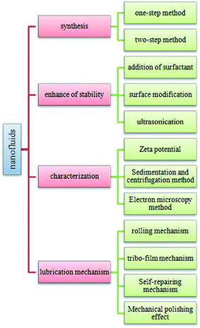
This paper aims at focusing on the existing knowledge and research gap in all fields of nanofluids from synthesis of nanofluids and to their research in tribological field. An exclusive review section on characterization techniques, improved and recent theoretical models for lubricating developed by different researchers are presented in this review paper as well. The structure of this review is given in Fig. 1.
2 Preparation of nanofluid
Nanoparticles, as the additives for nanofluids, play an important role in improving anti-wear, friction reduction and load carrying capacities of nanofluids. Various types of nanoparticles, such as metallic nanoparticles, metallic oxide, have been studied in recent years. Two preparation methods of nanofluids have been reported.2.1 Single-step method
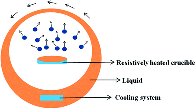
Single-step method is a procedure that combines the production of nanoparticles with the synthesis of nanofluids. Vapour Deposition, developed by Choi in 2001,21 is the most commonly used single-step method at present. The principle is shown in Fig. 2. Under the centrifugal force of the rotating disk, a flowing thin film of base liquid is formed on the wall of the vessel. Raw material is heated and evaporated in a resistively heated crucible, the vapor is condensed into nano-sized particles when it contacts the cold base liquid film, and nanofluid is obtained. Akoh et al.22 developed another single-step direct evaporation method, which is similar to Vacuum Evaporation onto a Running Oil Substrate (VEROS). Extremely fine particles with the average size of about 0.25 nm were obtained with this method. To successfully prepare well dispersed Cu nanofluid, a modified VEROS method was proposed by Eastman.23 In this method, Cu particles were produced by direct evaporation into a low vapor pressure liquid. Zhu et al.24 presented a single-step chemical process for the preparation of Cu nanofluid, in which CuSO4·5H2O is partly reduced with NaH2PO2·H2O in ethylene glycol under microwave irradiation. The TEM micrograph reveals that the size of most Cu particles is in the range of 10 nm and 20 nm. Choi et al.25 also developed a Direct Evaporation Condensation method. The main advantage of this method is the good controllability of nanoparticle size and long term stability of nanofluid. Lo et al.26 introduced a novel system was to prepare CuO nanofluid. The method is based on Submerged Arc Nanoparticle Synthesis System (SANSS) technique. SANSS mainly consists of a heating source, a state control system and a cooling unit.Solubility of nanoparticles is relevant to their size, the relationship can be described by eqn (1)
 | (1) |
Two main advantages were involved by using single-step method. The first advantage is no drying, storage or dispersing process is needed, thus reducing cost of production. The other advantage is low aggregation of nanoparticles predominately due to the first advantage mentioned above, it is extremely important to ensure the long term stability of nanofluids. The major disadvantage of single-step method is that it is merely compatible with low vapor pressure base fluids.
2.2 Two-step method
The sketch of two-step method is shown in Fig. 3. Currently, two-step method is the most commonly used method for the preparation of nanofluids. Generally, two procedures are involved in this method. The first procedure is the synthesis of nanomaterial, which is usually in the form of dry powder. The second procedure is the dispersion of nanomaterial in the base liquid such as water, ethanol and ethylene glycol. During this procedure, some measures, for instance, addition of dispersant or sonication, are generally carried out to enhance the stability of the resulting nanofluids.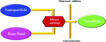 | ||
| Fig. 3 Preparation process of nanofluids by two-step method.59 | ||
Several nanofluids prepared with two-step method are listed in Table 1. Peng27 successfully prepared AlN/ethanol nanofluids with the aid of ultrasonic homogenizer. The preparation process was approximately as follows: firstly mixed the AlN and castor oil in the ethanol with vigorous stirring, then placed the mixture in an ultrasonic homogenizer for 10 minutes and eventually well dispersing AlN/ethanol nanofluid was gained. Diathermic oil based TiO2 nanofluid was fabricated via two-step method, where oleic acid (OA) was used as the dispersant to ensure the stability of nanofluid.28 Xuan et al.50 prepared Cu nanofluids of both water and transformer oil, well dispersed nanofluids were achieved when the percentage of dispersant amount reached 22 wt% of Cu nanoparticles. Two-step method was also used for the synthesis of CNT based nanofluids. Numerous of CNT nanofluids were prepared by dispersion of CNTs in various base fluids.52–55
| Nanoparticles | Base fluids | Ref. |
|---|---|---|
| TiO2 | Oil, bidistilled water, deionized water, EG-TNT | 28–31 |
| ZnO | PEG, EG, deionized water | 32–34 |
| SiO2 | TH66, deionized water, methanol | 35–37 |
| CuO | Oil, deionized water, oleic acid | 38–40 |
| Al2O3 | CMC, EG, deionized water, WEG50 | 41–44 |
| Fe3O4 | Kerosene, EG/water | 45,46 |
| Cu | R113, EG, deionized water, transformer oil | 47–50 |
| Ag | Deionized water | 51 |
| CNTs | Ammonia, deionized water, glycol, EG | 52–55 |
Compared with single-step method, the main disadvantage of two-step method is the instability of nanofluids because of the high surface energy of nanoparticles.56 Besides, the process of drying, storage and transportation of nanoparticles was inevitable in two-step method. However, this method also has advantages. Two-step method enables making nanofluids at a very large scale.57 Moreover, it could be used to make almost all kinds of nanofluids.58
3 Stability mechanisms of nanofluids
Stability is the most crucial issue for nanofluids because of the tendency of mutual attraction between nanoparticles which caused by high surface energy of nanoparticles. According to DLVO theory, there are two forces between nanoparticles, the one is van der Waals attractive force between nanoparticles while the other is electrical double layer repulsive force. The attractive potential energy is given by Hamaker formula, which is listed as eqn (2)
 | (2) |
 | (3) |
The stability of nanofluids is the result of the two opposing forces.60 If the repulsive force is much larger than the attractive force, and can overcome the attraction during the collision process due to Brownian movement, the nanofluid is in a relative stable state. Otherwise, the nanofluid is in an unstable state. Steric repulsion and electrostatic repulsion are the two types of mechanisms through which nanofluids are stabilized, as shown in Fig. 4. According to steric repulsion, several surfactants, such as SDBS, SDS, CTAB, can prevent the aggregation of dispersed nanoparticles in nanofluids. These surfactants usually have two tails, one is hydrophilic and the other is hydrophobic. The hydrophilic tail adsorbs onto the surface of nanoparticles with a long loop and the hydrophobic tail extends out into the nanofluids. Thus, steric stabilized nanofluids remain well dispersed and sustain for a long period. In electrostatic stabilization, the nanoparticles in nanofluids bear some charge because of adsorption of ions. Electrical double layer is created around nanoparticles, and the repulsive force produced by electrical layer will offset the attractive force between nanoparticles.
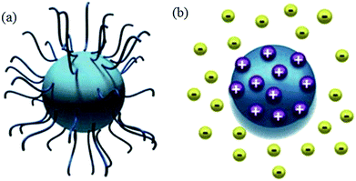 | ||
| Fig. 4 Type of nanofluids stabilization (a) steric stabilization (b) electrostatic stabilization.61 | ||
Avraham62 investigated the role of carbon chain in 3-alkyl thiophenes on the dispersing of CNTs in the organic solvents, and concluded that the stability was not only relied on the stacking of the polymer backbone onto the CNTs, but also on the steric repulsion of carbon chain of adsorbed 3-alkyl thiophenes. Yang et al.63 prepared Al2O3 ammonia/water nanofluids with sodium dodecyl benzene sulfonate (SDBS) as the dispersant. The stability of the nanofluids with different amount of SDBS was studied with light absorbency ratio index method. The results shows that with the increasing amount of surfactant, the stability of nanofluid is lowered first, and then improved, and then is lowered again. In this study, the stability of the nanofluid was first calculated based on the simplified dispersion model and the calculation agreed with the experimental results.
4 Techniques of nanoparticles dispersed in nanofluids
Some chemical and physical techniques can be used to modify the surface of nanoparticles to obtain a stable nanofluid through two-step method. Addition of surfactants and surface treatment of nanoparticles are discussed in the follow section. Sonication is discussed as well.4.1 Addition of dispersant
Addition of dispersant is an effective method to prevent the aggregation of nanoparticles, as the dispersant acts as a bridge between nanoparticles and base fluids, creating continuity between nanoparticles and base fluids.64 Addition of dispersants lowers the surface tension of base fluids and improves the immersion of nanoparticles.Commonly used dispersants are listed in Table 2. Gu65 prepared OA/La–TiO2 via sol–gel method in association with surface modification with oleic acid (OA). The OA/La–TiO2 nanoparticles were spherical with an average size of about 20 nm. Zin66 studied the stability of nano Cu in ethylene glycol, where SDS or PVP were used as dispersant. PVP proved to be a better stabilizer. Xia et al.67 compared the effects of PVP and SDS on the stability of Al2O3 nanofluids and found that both PVP and SDS can provide excellent stabilization for Al2O3 nanofluids. Gao et al.68 synthesized TiO2 nanoparticles with the average size of 30 nm, and then prepared TiO2 nanofluid with the aid of oleic acid (OA) as the dispersant. Commercially available Al2O3 nanofluid was prepared by two-step method, where SDS was used as the surfactant.69 Li70 compared the stability of CuO/water nanofluids with and without CTAB dispersant. The results revealed that CTAB could stabilize CuO nanofluid for one week, while in the nanofluid without CTAB aggregation occurred quickly. The stability of CNTs nanofluids were also enhanced in the presence of SDBS, Triton X-100, or gum arabic.71–74
Addition of dispersant is an effective and economic method to enhance the stability of nanofluids. However, the presence of dispersant can increase the viscosity of nanofluids. Generally, the tribological property of lubricant oil is enhanced with the increase of its viscosity. However, it is not the case for lubricant containing nanoparticles. High viscosity of nanofluids is bound to affect the liquidity of nanoparticles in the base fluid. As a result, insufficient number of nanoparticles enters the tribo-pairs when superfluous dispersant is added, and ultimately deteriorate the tribological property of lubricant. Additionally, dispersants are usually sensitive to temperature. At high temperature, dispersants could decompose and thus stay out of action.
4.2 Surface modification of nanoparticles
The surface of nanoparticles can be modified by functionalization. Simply adding functionalized nanoparticles into the base fluid, long term stability can be achieved. Wang75 developed an economic method for surface functionalization of gold nanoparticles, mixed DNA/PEG polymers were instead of original pure DNA in his method, sketch of functionalization was listed in Fig. 5. Compared with pure DNA modification, only a little amount of DNA was used to get same effect. Kim et al.76 prepared stable methanol based CeO2 nanofluid by dispersing the surface-modified ceria (CeO2) nanoparticles in methanol using ultrasonicator. Alzatecarvajal77 attempted modified graphene oxide and nanodiamond by amide functionalization, in this method, a solvent-free gas-phase treatment was involved, aromatic and aliphatic amines were also used. Finally he proved that amidation was the only possible route for functionalization of diamond. Pati et al.78 reported a simple approach to produce stable Fe3O4 nanofluid in the absence of dispersant: Fe3O4 nanoparticles were first prepared, separated, and washed with acetone and water, followed by soaking in NaOH solution and drying at 150 °C for 30 minutes, and finally the dried powder was dispersed in water and sonicated for 30 minutes. CNTs were modified with HNO3 and a mixture of HNO3/H2SO4, so that hydrophilic functional groups were introduced onto the surface. The CNTs/water nanofluid was subjected to ultrasonication and good stability was achieved despite of the absence of surfactant.79 Likewise, Aravind80 purified MWCNT with concentrated acids (H2SO4, HNO3 and H2SO4/HNO3 mixture) to introduce hydrophilic functional groups and satisfactory result was obtained.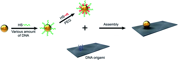 | ||
| Fig. 5 Surface modification of gold nanoparticles. Reproduced from ref. 75 with permission from the Royal Society of Chemistry. | ||
4.3 Ultrasonication
Ultrasonication is an accepted physical technique to disperse agglomerated nanoparticles into base fluid. However, it is always accompanied with chemical treatment, rather than an independent dispersing method.Teng81 prepared Al2O3/water nanofluids with different concentration, the nanofluids were dispersed by cationic dispersant (chitosan) accompanied with ultrasonic treatment. TiO2, ZnO and Al2O3 were dispersed in water/EG mixture fluid, the SDS was used as dispersant, followed by sonicated treatment for 1 hour aimed at enhancing stability of nanofluids.82 CuO/water nanofluid was prepared via sonicated treatment, long term stability was achieved although no surfactant was added.83 The surface of the MWCNT is modified by acid treatment and then dispersed in water/ethylene glycol by sonication for nearly 40 min using a 100 W, 40 kHz ultrasonicator.80
Although ultrasonication has been accepted as an essential step in the preparation of nanofluids through two-step method, there is no standard for ultrasonic time and wave. And what type pulse mode should be taken is also kept unknown. Mahbubul84 investigated the effect of ultrasonication duration on the stability of Al2O3/water nanofluids, where the particles size distribution and zeta potential were analysed to explore the dispersion of Al2O3 in water, and they found that cluster size decreased while zeta potential increased with the increase of ultrasonication duration in the first 3 hours. Nguyen85 evaluated the main parameters of ultrasonication such as power and irradiation modes on the cluster size of Al2O3 in the aqueous solutions, he pointed out that both continuous and pulsed irradiation were helpful to reduce the size of Al2O3 cluster, besides, optimal break up efficiency could be achieved at a vibration amplitude of 30%.
There are contradictory results among the literatures about the effect of ultrasonication duration on the stability of nanofluids. So more attempts should be take into effect to explore the optimum duration.
5 Characterization of nanofluids
Characterization of nanofluids always reveals several important details such as nanoparticle shape, size, distribution and stability of nanoparticles in base fluid. The most commonly used characterization means include zeta potential analysis, sedimentation method, and electron microscopy.5.1 Zeta potential analysis
The liquid layer surrounding the particles contains two different regions; an inner region (stern layer) and an outer (diffuse) region. At the inner region ions are firmly bound and at the outer region they are loosely associated. There is a notional boundary inside the outer layer where the particles and ions form a stable entity. The potential at this boundary is known as zeta potential. The main advantage of zeta potential analysis is that it is quick. When the absolute value of zeta potential is high, the repulsive force between nanoparticles will prevail and the nanofluid is in stable state. On the contrary, if the absolute value of zeta potential is low, the attractive force is dominating and the nanofluid tends to aggregate. The relationship is listed in Table 3.| Zeta potential (mV) | Stability of nanofluid |
|---|---|
| 0 | Very little or no stability |
| 15 | Little stability with settling |
| 30 | Moderate stability with sedimentation |
| 45 | Good stability with possible settling |
| 60 | Excellent stability, little settling |
As shown in Table 3, nanofluids with zeta potential higher than 30 mV are relatively stable and above 60 mV show excellent stability with little settling. When zeta potential is below 15 mV, a nanofluid is in unstable state, and when zeta potential is closed to 0 mV, nanofluid undergoes significant aggregation. Due to a large negative zeta potential in water, Au/water nanofluids without any dispersant were prepared and exhibit good stability.87 Li et al.88 systematically studied the effects of pH, various dispersants, and concentration on zeta potential of Cu/water nanofluids, and the results showed that at pH 9.5, the absolute value of zeta potential is remarkably higher with the addition of SDBS or CTAB. The aggregation stability of aqueous dispersion of the hydrated anatase and rutile sample in the neutral and alkaline pH regions were related to the electrostatic stabilization and were explained through DLVO theory.89 Stability and zeta potential of graphite nanofluids at different pH value have been investigated and higher zeta potential was obtained in acidic nanofluid.90 Himansu91 evaluated the stability of surface modified CeO2 nanoparticles in deionized water by zeta potential method, and found that the value reached 42 mV, and 10 mV higher than that of unmodified nanoparticles.
5.2 Sedimentation and centrifugation
Sedimentation is the tendency of nanoparticles to settle out of the base fluid in which they are dispersed and finally come to rest against an external force. At steady state, sedimentation velocity of spherical particles is given by Stokes law as eqn (4):
 | (4) |
According to Stokes law, sedimentation velocity decreases when nanoparticles become smaller. Thus, sedimentation will be slow for smaller nanoparticles relative to large nanoparticles dispersed in base fluid.
Sedimentation and centrifugation are the most commonly used method to investigate the stability of nanofluids because of the simplicity operation.92,93 The stability of nanofluid is directly indicated by the mass or volume of sediment. Nanofluids are considered stable when the concentration or particle size in the supernatant stays constant. Zhu90 evaluated the stability of graphite nanofluids with sedimentation balance method. The results revealed that the nanofluid was more stable when PVP concentration was higher than 0.4 wt%. Angayarkanni and Philip94 studied the stability of water based alumina nanofluids at different time intervals by sedimentation and confirmed that the sedimentation rates of different kinds of nanofluids were all in accord with their time depended thermal conductivity measurement.
5.3 Electron microscopy
Electron microscopy is generally used to investigate the stability of nanofluids by observing the distribution and aggregation of nanoparticles. Generally it is used for characterizing the morphology of nanoparticles before dispersion. Transmission electron microscopy (TEM) provides high resolution images that can reach approximately 0.1 nm in case of lattice images. Aggregation of nanoparticles within the nanofluids can be directly monitored with TEM.Li95 observed the morphology of Y2O3-stabilized ZrO2 nanoparticles without and with different surfactant, confirmed that the average size of nanoparticles modified by polyether amine D2000 or PVP-10000 was smaller than modified by PEG-4000 or without any surfactant. Yang96 successfully prepared oleic acid-modified lanthanum trifluoride–graphene oxide nanohybrids and observed the morphology with TEM. A typical TEM image of graphene oxide (GO) that presents highly transparent films and LaF3–GO structure formed by LaF3 nanoparticles on the surface of GO is seen in his experiment. Nanodiamond-agglomerate on Cu grid with lacey carbon was characterized with TEM97 as well.
The characterization of nanoparticles dispersed in base fluid with TEM, the usual practice is placing a drop of as-prepared nanofluids onto a copper grid coated with a carbon film, and then observes the distribution of nanoparticles on copper grid when base fluid is completely evaporated. There is one point should be noted, the evaporation of base fluid always accompanies with aggregation of nanoparticles. As a result, the characterization mean by TEM is only available when less nanoparticles in base fluid. Cryo-EM may be a potential substitute in the future.
6 Lubricating mechanisms of nanoparticles in nanofluids
During the past two decades, the application of nanofluids in lubrication has made substantiates progress. Because of the low melting point and high chemical reactivity, nanoparticles may deposit on the microdefects of rubbing surfaces, and play a role of “self-repairing” to a certain degree. This is a great potential advantage of nanofluids on lubrication. Furthermore, the thermal conductivity of nanofluids is usually higher than that of their base fluid, which will help to release the heat produced in the friction and maintain the stability of the tribo-pairs. Finally, most nanoparticles are environmentally friendly, as an alternative of traditional additives which commonly containing sulfur and phosphorus, this is very beneficial to the sustainability of the environment and economy. At present, four lubrication mechanisms are commonly accepted: rolling, polishing, self-mending and tribo-film mechanism. Additionally, nanoparticles are also effective in lubrication because of sintering or melt on the tribo-film.6.1 Rolling mechanism
The friction mode is influenced by the well distributed spherical nanoparticles in the nanofluids, because they can switch from sliding friction to rolling friction. And the load carrying capacity is also improved. Kao98 evaluated the role of spherical TiO2 nanoparticles in friction reduction, and found that TiO2 can reduce the worn scar depth by 80.84%, which might be attributed to rolling effect at high temperature. Luo99 synthesized Al2O3/TiO2 nanocomposites with an average size of 75 nm, and investigated the friction and wear properties of the nanocomposites in lubricating oil. They found that the addition of Al2O3/TiO2 enhanced the tribological performance of the lubricating oil, possibly due to wear behavior switching from sliding friction to rolling friction during the process.Rolling mechanism theory proposes that two factors contribute to the excellent lubrication effect of nanofluids. One is that the nanoparticles are usually spherical, and they may act as “micro-bearing” during the friction; the other is at high temperature and load, the nanoparticles between two rubbing surfaces become flat and form a “sliding system”, which ultimately reduces the friction and wear. Mahdi Khadem100 explored the tribological behavior of nanodiamond on two kinds of rubbing surfaces with different hardness, and claimed that nano-diamond were likely to get embedded into the surface of the soft specimen, rolling effect occurred only when rubbing surfaces own comparatively higher hardness. The embedded and rolling mechanism is illustrated in Fig. 6.
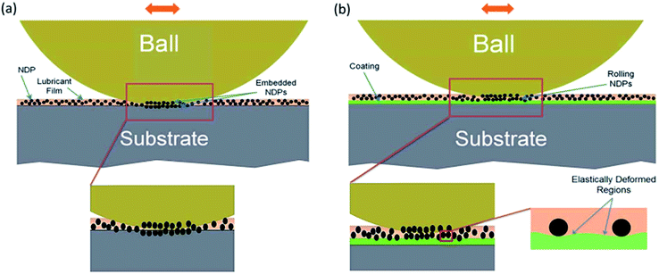 | ||
| Fig. 6 Schematic illustration on the effects of NDPs in the lubricant for (a) bare and (b) coated stainless steel specimens. Reproduced from ref. 100 with permission from the Royal Society of Chemistry. | ||
6.2 Tribo-film mechanism
Nanoparticles that well dispersed in nanofluids are liable to form a thin film on the metal surface, and this film is dense and low shear, which can separate the rub surface and reduce the friction. In the process of friction, the nanoparticles in the nanofluid tend to migrate to the rubbing surface due to two factors. The one is that the local high temperature because of friction may arouse nanoparticles' undulations in the rubbing surface is fiercer than that in the nanofluids. Random migration is more active as a result of this undulation, and ultimately increase the chance of nanoparticles migrates to the rubbing surface. The other is that the exoelectrons produced during the friction accelerate to strengthening electric-field the on the rubbing surface, the existence of electrical field may cause the gathering of nanoparticles on the rubbing surface.Tribo-film mechanism is the most prevailing theory to explain the anti-wear and friction reduction behaviour of nanofluids. Most scientists and researchers attributed better lubrication performance of nanofluids to the fact that nanoparticles being deposited on rubbing surfaces and forming a protect film.
Wu101 prepared OA modified ZnO/PAO nanofluid and studied the wear mechanism of ZnO nanoparticles in PAO, he declared that nanoparticles could easily enter into sliding metal surface due to their small size. These nanoparticles also proved to be easy to adsorb or deposit on the sliding metal surface to form a surface protective film and thus reduce the friction. Zhang102 prepared Cu/SiO2 nanocomposite and evaluated its tribological properties in water-based lubricant, and found that during the friction process, a protective and lubricious film composed of Cu and a small amount of Fes, FeSO4 and SiO2 is formed on the rubbed steel surface. Abad103 systematically studied the tribological behavior of the Pd NPs dispersed in TBA that carried out by different experimental parameters, the Pt NPs directly deposited onto the contact surface and formed a protective film was been proven in his study. Chen104 synthetized stearic acid-capped cerium borate (SA/CeBO3) and studied the friction and wear performances of SA/CeBO3 in rapeseed oil. The results indicated that SA/CeBO3 adsorbed and triboreacted to form B2O3, CeO2 and Fe2O3 on the rubbing surface.
Although most scientists claimed that nanoparticles deposited into a protective film on the rubbed surface during the process of friction, as they detected the existence of nanoparticles on the wearing surface. The amounts of deposited nanoparticles were minor or ambiguous.105,106 A hypothesis could be proposed. Continuous and dense film might be not formed since a small quantity of deposited nanoparticles were discoverable in these literatures.
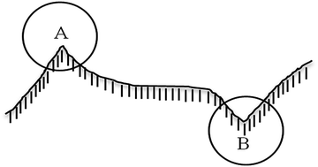
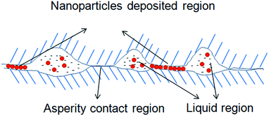
The deposition of nanoparticles on a given solid was depended on the surface energy of this solid. Fig. 7 presents the profile sketch of a non-smooth surface, where location A represents asperity while B stands for valley. It's easily concluded that the surface energy of location A is higher than that of location B based on definition of solid surface energy. Thus nanoparticles are more likely to deposit on asperity of solid surface. According to Kong,107 heterogeneous deposition of nanoparticles on wearing surface will cause the transition of lubrication mechanism, which is changed from traditional mixed lubrication to a new synergistic lubrication that comprised with asperity, nanoparticles and liquid film, as shown in Fig. 8.
6.3 Self-repairing mechanism
Nanoparticles in nanofluids tend to fill the microcracks and repair microdamages via desorption or deposition on rubbing surface, and eventually help to form more flat and smooth surfaces. Usually, a soft metal whose structure is face-centered cubic has the capacity of “self-mending”. Wang108 pointed out that nano-copper in lubricating oil form a film which separates the friction materials in the friction process. Ma109 studied the effect of Ag nanoparticles as additives for multi-alkylated cyclopentanes and found that Ag nanoparticles deposited on the friction surfaces to form metallic Ag boundary film. The protective metal film had low shearing stress and contributed to preventing the steel-to-steel contact from severe adhesion, scuffing, and seizure. Flores-Castañeda110 also concluded that the wear rate reduction by bismuth nanoparticle additives was resulted from the tribo-sintering of nanoparticles on the rubbing surfaces reducing the metal-to-metal contact and acting as a low friction load-bearing film.It is worth mentioning that, “self-repairing” mechanism is not simply an accumulation of nanoparticles on the rubbing surface. With the decreasing size of nanoparticles, their melting points decline sharply. At the high temperature of rubbing surfaces, these nanoparticles are easily melted or sintered in the microcracks of the contact area, and sequential filler is formed and closely tied to the rubbing surface.
6.4 Mechanical polishing effect
Hard nanoparticles in nanofluids act as an excellent polishing tool and play a role in mechanical polishing on rubbing surfaces in the process of friction. The real contacting area of tribo-pairs is increased due to smoother surface polished with hard nanoparticles, which ultimately lowers the friction coefficient and increase the load carrying capacity.As for the surface with a high roughness, nanoparticles do not exhibit good mechanical polishing effect in terms of improving the tribological properties of the nanofluids, because nanoparticles are too small for the rough surfaces. They can merely repair the surface at the atomic scale. Thus, mechanical polishing effect is more evident when the tribo-pairs have a low surface roughness.
Chou111 observed the surface morphology of 6061 aluminium alloys lubricated separately by commercial oil and nanofluids containing 0.05% nanodiamond, and found that the surface roughness of aluminium alloy lubricated by nanofluid was decreased by 15% compared with that lubricated by commercial oil, he pointed that it was polishing action of diamond nanoparticles resulted in the final smoother surface. Tao19 evaluated the ball-bearing effect of diamond nanoparticle in base oil, and confirmed that initially the diamond nanoparticles mainly take the effect of surface polishing.
A common phenomenon is that almost all tribological tests prove that the rubbed surfaces lubricated by nano lubricants are much smoother. However, it's not sufficient to attribute it to the polishing effect of nanoparticles, because of self-repairing, nanoparticles are easily deposited filled into the microcracks and grooves and flat surface can also be gained.
6.5 Diversification of lubrication mechanism
In most cases, the nanoparticles do not work by a single lubrication effect, but by two or more mechanisms. Besides, there may be a transition during different mechanisms when changed lubrication condition occurs.Zareh-Desari112 studied the lubrication properties of SiO2 and CuO nanoparticles in vegetable oil, and claimed that two mechanisms were involved in the process of friction, one was the rolling effect and the other was self-repairing mechanism. Zheng113 discussed the synergistic lubrication mechanism of Fe3O4/MoS2 nanocomposites in aqueous and oil phase media, he argued that nanoball bearing of Fe3O4 and tribo-film formed with MoS2 might contribute to the friction reducing and anti-wear performances of nanofluids.
Although plenty of works have been done on the tribological performance of nanofluids. Most studies in the field of analysis on lubrication mechanism always focus on the effect of nanoparticles. In fact, the mutual interactions among the nanoparticles, dispersant and base fluid should be also taken into consideration.
7 Problems of nanofluids in lubrication
Although nanofluids show excellent tribological properties in lubrication, there are still some problems to be solved.The most important issue is the dispersion and stability of nanoparticles in nanofluids. Nanoparticles have large specific surface area, high chemical reactivity, wide diffusivity and high absorption. All these characteristics are the prerequisite of nanoparticles to form protective film or repair the rubbing surfaces. However, these characteristics also lead to poor stability and dispersion as well. Aggregation of nanoparticles can even cause severe abrasive wear. Usually, surfactants or modification of the surface of nanoparticles can be used to reduce the surface energy of nanoparticles to alleviate the aggregation. However, the selection and appropriate level of surfactants and the improvement of modification technology are still barriers for the application of nanofluids in lubrication.
Another problem in nanofluids is the rough edges related to lubrication mechanisms of nanofluids. The lubrication mechanisms of nanofluids, such as micro-rolling mechanism, still have not been validated by direct experimental data. And some views are somewhat farfetched to explain the lubrication phenomenon. For example, nano-copper shows good tribological properties under high load. Some literatures108,114–116 tried to explain that by deposition of nano-copper and formation of a protect film. However, copper film itself is not helpful to improve lubrication under high pressure.
8 Conclusion
The present review covers the preparation and analytical techniques of nanofluids and the lubrication mechanisms in tribology. Although much progress has been made, it is still a challenge to make a homogenous and long-term stable nanofluid with negligible agglomeration and little effect on the tribological properties.There are two methods to prepare nanofluids. Nanofluids prepared by single-step method are more stable than those by two-step method. However, the two-step method is applicable in the fabrication of almost all kinds of nanofluids.
Three techniques can be used to improve the stability of nanofluids. Compared to surfactants, surface modification seems to be more effective to achieve stable nanofluids and it exerts less influence on the physicochemical properties of nanofluids. As an auxiliary method, ultrasonication is always accompanied by the addition of surfactant or surface modification.
A common view in several reports is the deposition of nanoparticles in the gaps and grooves of the rubbing surfaces is responsible for improved tribological performance, this claim need to be substantiated with appropriate experimental results and theoretical models. Further detailed tribological studies using DLS, SEM, TEM, AFM and XPS are indispensable for insight into the interaction between nanoparticles and contact surface.
Acknowledgements
The present study is financially supported by the National Natural Science Foundation of China (51274037).References
- Z. Y. Xu, Y. Xu and K. H. Hu, et al., Tribol. Int., 2015, 81, 139–148 CrossRef CAS.
- S. Ma, S. Zheng and D. Cao, et al., Particuology, 2010, 8(5), 468–472 CrossRef CAS.
- R. Liu, X. Wei and D. Tao, et al., Tribol. Int., 2010, 43(5–6), 1082–1086 CrossRef CAS.
- D. Kim and L. A. Archer, Langmuir, 2011, 27(6), 3083–3094 CrossRef CAS PubMed.
- V. Zin, F. Agresti and S. Barison, et al., IEEE Trans. Nanotechnol., 2013, 12(5), 751–759 CrossRef CAS.
- M. H. Kayhani, H. Soltanzadeh and M. M. Heyhat, et al., Int. Commun. Heat Mass Transfer, 2012, 39(3), 456–462 CrossRef CAS.
- M. Asrul, N. W. M. Zulkifli and H. H. Masjuki, et al., PLoS One, 2013, 68(12), 320–325 CAS.
- T. Luo, X. Wei and H. Zhao, et al., Ceram. Int., 2014, 40(7), 10103–10109 CrossRef CAS.
- S. M. Alves, B. S. Barros and M. F. Trajano, et al., Tribol. Int., 2013, 65(3), 28–36 CrossRef CAS.
- F. ChiñAs-Castillo and H. A. Spikes, J. Tribol., 2003, 125(3), 552–557 CrossRef.
- J. L. Viesca, A. H. Battez and R. González, et al., Tribol. Int., 2011, 44(7), 829–833 CrossRef CAS.
- G. Liu, X. Li and B. Qin, et al., Tribol. Lett., 2004, 17(4), 961–966 CrossRef CAS.
- X. Zhou, X. Fu and H. Shi, et al., Lubr. Sci., 2007, 19(1), 71–79 CrossRef CAS.
- A. H. Battez, J. E. F. Rico and A. N. Arias, et al., Wear, 2006, 261(3–4), 256–263 CrossRef.
- T. Shen, D. Wang and J. Yun, et al., Tribol. Int., 2015, 93 Search PubMed.
- B. Chen, K. Gu and J. Fang, et al., Appl. Surf. Sci., 2015, 353, 326–332 CrossRef CAS.
- H. L. Yu, Y. Xu and P. J. Shi, Trans. Nonferrous Met. Soc. China, 2008, 18(3), 636–641 CrossRef CAS.
- F. Zhao, Z. Bai, Y. Fu and D. Zhao, Wear, 2012, 288, 72–77 CrossRef CAS.
- X. Tao, Z. Jiazheng and X. Kang, J. Phys. D: Appl. Phys., 1996, 29(11), 2932–2937 CrossRef CAS.
- D. Peng, C. Chen and Y. Kang, et al., Ind. Lubr. Tribol., 2010, 62(2), 111–120 CrossRef.
- S. U. S. Choi and J. A. Eastman, US Pat. 6221275 B1 [P]. 2001.
- H. Akoh, Y. Tsukasaki and S. Yatsuya, et al., J. Cryst. Growth, 1978, 45(2), 495–500 CrossRef CAS.
- J. A. Eastman, U. S. Choi and S. Li, et al., Mater. Res. Soc. Symp. Proc., 1995, 457 Search PubMed.
- H. T. Zhu, Y. S. Lin and Y. S. Yin, J. Colloid Interface Sci., 2004, 277(1), 100–103 CrossRef CAS PubMed.
- U. S. Choi, W. Yu and J. R. Hull, et al., SAE [Tech. Pap.], 2002, 38–43 Search PubMed.
- C. H. Lo, T. T. Tsung and L. C. Chen, et al., J. Nanopart. Res., 2005, 7(2–3), 313–320 CrossRef CAS.
- H. Peng, W. L. Shan and F. Yu, et al., Int. J. Thermophys., 2008, 29(6), 1968–1973 CrossRef.
- B. Wei, C. Zou and X. Li, Int. J. Heat Mass Transfer, 2017, 104, 537–543 CrossRef CAS.
- S. Mo, Y. Chen and L. Jia, Appl. Energy, 2012, 93(5), 65–70 CrossRef CAS.
- L. Fedele, L. Colla and S. Bobbo, Int. J. Refrig., 2012, 35(5), 1359–1366 CrossRef CAS.
- H. Chen, Y. Ding and A. Lapkin, Powder Technol., 2009, 194(1–2), 132–141 CrossRef CAS.
- M. T. J. Zafarani, Chem. Thermodyn., 2012, 54, 55–67 CrossRef.
- G. J. Lee, K. K. Chang and K. L. Min, et al., Thermochim. Acta, 2012, 542(542), 24–27 CrossRef CAS.
- V. S. Raykar and A. K. Singh, Thermochim. Acta, 2010, 502(1), 60–65 CrossRef CAS.
- E. V. Timofeeva, M. R. Moravek and D. Singh, J. Colloid Interface Sci., 2011, 364(1), 71–79 CrossRef CAS PubMed.
- K. Anoop, R. Sadr and J. Yu, et al., Int. Commun. Heat Mass Transfer, 2012, 39(9), 1325–1330 CrossRef CAS.
- C. Pang, J. Y. Jung and J. W. Lee, et al., Int. J. Heat Mass Transfer, 2012, 55(21–22), 5597–5602 CrossRef CAS.
- M. Saeedinia, M. A. Akhavan-Behabadi and M. Nasr, Exp. Therm. Fluid Sci., 2011, 36(1), 158–168 Search PubMed.
- S. M. Fotukian and M. N. Esfahany, Int. Commun. Heat Mass Transfer, 2010, 37(2), 214–219 CrossRef CAS.
- S. Harikrishnan and S. Kalaiselvam, Thermochim. Acta, 2012, 533(533), 46–55 CrossRef CAS.
- S. Soltani, S. G. Etemad and J. Thibault, Int. Commun. Heat Mass Transfer, 2010, 37(1), 29–33 CrossRef CAS.
- M. P. Beck, T. Sun and A. S. Teja, Fluid Phase Equilib., 2007, 260(2), 275–278 CrossRef CAS.
- J. Y. Jung, E. S. Kim and Y. T. Kang, Int. Commun. Heat Mass Transfer, 2012, 55(s7–8), 1941–1946 CrossRef CAS.
- M. R. Raveshi, A. Keshavarz and M. S. Mojarrad, et al., Exp. Therm. Fluid Sci., 2013, 44(1), 805–814 CrossRef CAS.
- W. Yu, H. Xie and L. Chen, et al., Colloids Surf., A, 2010, 355(1), 109–113 CrossRef CAS.
- L. S. Sundar, E. V. Ramana and M. K. Singh, et al., Chem. Phys. Lett., 2012, 554(6), 236–242 CrossRef.
- H. Peng, G. Ding and H. Hu, Exp. Therm. Fluid Sci., 2011, 35(6), 960–970 CrossRef CAS.
- E. D. Robertis, E. H. H. Cosme and R. S. Neves, et al., Appl. Therm. Eng., 2012, 41(41), 10–17 CrossRef.
- R. Kathiravan, R. Kumar and A. Gupta, et al., Int. Commun. Heat Mass Transfer, 2012, 33(2), 69–78 CAS.
- Y. Xuan and L. I. J. Qiang, J. Eng. Thermophys., 2000, 21(1), 58–64 CAS.
- T. X. Phuoc, Y. Soong and M. K. Chyu, Optic. Laser. Eng., 2007, 45(12), 1099–1106 CrossRef.
- F. Su, X. Ma and Z. Lan, J. Taiwan Inst. Chem. Eng., 2011, 42(2), 252–257 CrossRef CAS.
- Z. H. Liu, X. F. Yang and J. G. Xiong, Int. J. Therm. Sci., 2010, 49(7), 1156–1164 CrossRef CAS.
- M. Zhaoguo and W. Daxiong, et al., Particuology, 2012,(5), 614–618 Search PubMed.
- M. S. Liu, C. C. Lin and I. T. Huang, et al., Int. Commun. Heat Mass Transfer, 2005, 32(9), 1202–1210 CrossRef CAS.
- H. A. Mohammed, A. A. Al-Aswadi and N. H. Shuaib, et al., Renewable Sustainable Energy Rev., 2011, 15(6), 2921–2939 CrossRef CAS.
- H. Yu, S. Hermann and S. E. Schulz, et al., Chem. Phys., 2012, 408(408), 11–16 CrossRef CAS.
- X. Q. Wang and A. S. Mujumdar, J. Colloid Interface Sci., 2007, 46(1), 1–19 Search PubMed.
- S. A. Angayarkanni and J. Philip, Adv. Colloid Interface Sci., 2015, 225, 146–176 CrossRef CAS PubMed.
- I. Popa, G. Gillies and G. Papastavrou, et al., J. Phys. Chem. B, 2010, 114(9), 3170–3177 CrossRef CAS PubMed.
- W. Yu and H. Xie, J. Nanomater., 2012, 435873 Search PubMed.
- A. Bar-Hen, C. Bounioux and R. Yerushalmi-Rozen, J. Colloid Interface Sci., 2015, 452, 62–68 CrossRef CAS PubMed.
- L. Yang, K. Du and X. Niu, et al., Int. J. Refrig., 2011, 34(8), 1741–1748 CrossRef CAS.
- H. Yu, S. Hermann and S. E. Schulz, et al., J. Chem. Phys., 2012, 408(408), 11–16 CAS.
- K. Gu, B. Chen and Y. Cheng, J. Rare Earths, 2013, 31(6), 589–594 CrossRef CAS.
- V. Zin, F. Agresti and S. Barison, et al., IEEE Trans. Nanotechnol., 2013, 12(5), 751–759 CrossRef CAS.
- G. Xia, H. Jiang and R. Liu, et al., Int. J. Therm. Sci., 2014, 84(4), 118–124 CrossRef CAS.
- Y. Gao, G. Chen and Y. Oli, et al., Mater. Sci. Eng., A, 2000, 252(5–6), 454–458 Search PubMed.
- H. K. Sang, R. C. Sun and D. J. Kim, J. Heat Transfer, 2007, 129(3), 298–307 CrossRef.
- X. Li, D. Zhu and X. Wang, J. Colloid Interface Sci., 2007, 310(2), 456–463 CrossRef CAS PubMed.
- V. Kumaresan, Thermochim. Acta, 2012, 545, 180–186 CrossRef CAS.
- T. Yousefi, E. Shojaeizadeh and F. Veysi, et al., J. Sol. Energy, 2012, 86(2), 771–779 CrossRef CAS.
- A. Indhuja, K. S. Suganthi and S. Manikandan, et al., J. Taiwan Inst. Chem. Eng., 2013, 44(3), 474–479 CrossRef.
- P. Garg, J. L. Alvarado and C. Marsh, Int. J. Heat Mass Transfer, 2009, 52(21–22), 5090–5101 CrossRef CAS.
- R. Wang, I. Bowlinga and W. Liub, RSC Adv., 2017, 7, 3676–3679 RSC.
- J. Kim, Y. S. Park and B. Veriansyah, et al., Chem. Mater., 2008, 20(20), 6301–6303 CrossRef CAS.
- N. Alzatecarvajal, E. V. Basiuk and V. Mezalaguna, RSC Adv., 2016, 6, 113596–113610 RSC.
- S. S. Pati, V. Mahendran and J. Philip, J. Nanofluids, 2013, 2(2), 94–103 CrossRef CAS.
- H. Xie, H. Lee and W. Youn, et al., J. Appl. Phys., 2003, 94(8), 4967–4971 CrossRef CAS.
- S. S. J. Aravind, P. Baskar and T. T. Baby, et al., J. Phys. Chem. C, 2011, 115(34), 16737–16744 CAS.
- T. P. Teng, H. G. Hsu and H. E. Mo, et al., J. Alloys Compd., 2010, 504(504), S380–S384 CrossRef.
- H. K. Sang, R. C. Sun and D. J. Kim, J. Heat Transfer, 2007, 129(3), 298–307 CrossRef.
- N. Kannadasan, K. Ramanathan and S. Suresh, Exp. Therm. Fluid Sci., 2012, 42(5), 64–70 CrossRef CAS.
- I. M. Mahbubul, I. M. Shahrul and S. S. Khaleduzzaman, Int. J. Heat Mass Transfer, 2015, 88, 73–81 CrossRef CAS.
- V. S. Nguyen, D. Rouxel and R. Hadji, Ultrason. Sonochem., 2011, 18(1), 382–388 CrossRef CAS PubMed.
- A. Ghadimi, R. Saidur and H. S. C. Metselaar, Int. J. Heat Mass Transfer, 2011, 54(17–18), 4051–4068 CrossRef CAS.
- H. J. Kim, I. C. Bang and J. Onoe, Optic. Laser. Eng., 2009, 47(5), 532–538 CrossRef.
- X. Li, D. Zhu and X. J. Wang, J. Colloid Interface Sci., 2007, 310(2), 456–463 CrossRef CAS PubMed.
- B. V. Eremenko, T. N. Bezuglaya and A. N. Savitskaya, et al., Colloid J., 2001, 63(2), 173–178 CrossRef CAS.
- H. Zhu, C. Zhang and Y. Tang, et al., Carbon, 2007, 45(1), 226–228 CrossRef CAS.
- S. N. Himansu, RSC Adv., 2016, 6, 111889–111894 RSC.
- X. Li, D. Zhu and X. Wang, J. Colloid Interface Sci., 2007, 310(2), 456–463 CrossRef CAS PubMed.
- X. Wei and W. Liqiu, Particuology, 2010, 8(3), 262–271 CrossRef CAS.
- S. A. Angayarkanni and J. Philip, J. Nanofluids, 2014, 3(1), 17–25 CrossRef CAS.
- D. Li, Y. Xie and H. Yong, RSC Adv., 2017, 7, 3727–3735 RSC.
- C. Yang, X. Hou and Z. Li, et al., Appl. Surf. Sci., 2015, 388, 497–502 CrossRef.
- O. Elomaa, J. Oksanen and T. J. Hakala, Tribol. Int., 2014, 71(1), 62–68 CrossRef CAS.
- M. J. Kao and C. R. Lin, J. Alloys Compd., 2009, 483(1), 456–459 CrossRef CAS.
- T. Luo, X. Wei and H. Zhao, et al., Ceram. Int., 2014, 40(7), 10103–10109 CrossRef CAS.
- M. Khadem, O. V. Penkov and V. E. Pukha, RSC Adv., 2016, 6(62), 56918–56929 RSC.
- L. Wu, Y. Zhang and G. Yang, RSC Adv., 2016, 6, 69836–69844 RSC.
- C. Zhang, S. Zhang and L. Yu, et al., Appl. Surf. Sci., 2012, 259(42), 824–830 CrossRef CAS.
- M. D. Abad and J. C. Sánchez-López, Wear, 2013, 297(1–2), 943–951 CrossRef CAS.
- B. Chen, K. Gu and J. Fang, et al., Appl. Surf. Sci., 2015, 353, 326–332 CrossRef CAS.
- R. Chou, A. H. Battez and J. J. Cabello, Tribol. Int., 2010, 43(12), 2327–2332 CrossRef CAS.
- T. Sui, B. Song and F. Zhang, RSC Adv., 2016, 6(1), 393–402 RSC.
- L. Kong, J. Sun and Y. Bao, Wear, 2017, WEA101998 Search PubMed.
- X. L. Wang, Y. L. Yin and G. N. Zhang, et al., Phys. Procedia, 2013, 50, 466–472 CrossRef CAS.
- J. Ma, Y. Mo and B. Mingwu, Wear, 2009, 266(7–8), 627–631 CrossRef CAS.
- M. Flores-Castañeda, E. Camps and M. Camacho-López, et al., J. Alloys Compd., 2014, 643, S67–S70 CrossRef.
- C. C. Chou and S. H. Lee, J. Mater. Process. Technol., 2008, 201(1), 542–547 CrossRef CAS.
- B. Zareh-Desari and B. Davoodi, J. Cleaner Prod., 2016, 135, 1198–1209 CrossRef CAS.
- X. Zheng, Y. Xu and J. Geng, et al., Tribol. Int., 2016, 102, 79–87 CrossRef CAS.
- X. F. Sun, Y. L. Qiao and W. Song, et al., Phys. Procedia, 2013, 50, 343–347 CrossRef CAS.
- P. J. Shi, H. L. Yu and H. M. Wang, et al., Phys. Procedia, 2013, 50, 461–465 CrossRef CAS.
- Y. Choi, C. Lee and Y. Hwang, et al., Curr. Appl. Phys., 2009, 9(2), e124–e127 CrossRef.
| This journal is © The Royal Society of Chemistry 2017 |


