 Open Access Article
Facile assembly of a S@carbon nanotubes/polyaniline/graphene composite for lithium–sulfur batteries
Huihui Denga,
Libing Yaoa,
Qiu-An Huanga,
Qingmei Sua,
Jun Zhangab,
Fumin Zhang*a and
Gaohui Du *a
*a
aInstitute of Physical Chemistry, Zhejiang Normal University, Jinhua 321004, China. E-mail: zhangfumin@zjnu.cn; gaohuidu@zjnu.edu.cn
bCollege of Materials Science and Engineering, Zhejiang University of Technology, Hangzhou, 310014, China
First published on 2nd February 2017
Abstract
A carbon nanotube/polyaniline/graphene (MWCNT–PANI–G) composite as sulfur host has been prepared by a simple self-assembly approach with potential application for lithium–sulfur (Li–S) batteries. Scanning electron microscopy (SEM), transmission electron microscopy (TEM) and X-ray photoelectron spectroscopy (XPS) were used to investigate the microstructures and morphology of the as-prepared samples. It is demonstrated that the sulfur can be evenly impregnated into the MWCNT–PANI–G composite with strong chemical bonding. The resultant S@MWCNT–PANI–G composite with a sulfur content of 68 wt% shows excellent electrochemical performance as cathode for Li–S batteries. It delivers a high initial discharge capacity up to 1290 mA h g−1, good capacity retention of 784 mA h g−1 after 100 cycles of charge/discharge at the current density of 330 mA g−1, and good rate capability of 663 mA h g−1 and 548 mA h g−1 at 1.65 and 3.3 A g−1, respectively. The remarkable electrochemical performances are mainly attributed to the unique architecture of MWCNT–PANI–G with an enhanced electronic and ionic conductivity. Furthermore, this special architecture can provide strong physical and chemical confinement to the active materials and the soluble lithium polysulphides. Therefore, our study demonstrates a facile and low-cost approach to fabricate cathode materials for high-performance Li–S batteries.
1. Introduction
Among all of the energy storage technologies, lithium–sulfur (Li–S) batteries have attracted tremendous interest owing to their high energy density of 2600 W h kg−1 and extremely high theoretical specific capacity of 1675 mA h g−1, which is based on two-step redox reactions of sulfur and lithium.1,2 In addition, sulfur is also an abundant material in the world with non-toxicity and environmental compatibility. In spite of these advantages, Li–S batteries are restricted for practical application because of these inherent defects, including poor electronic conductivity of sulfur, large volume change during the lithiation process, and the shuttle effect caused by dissolution of intermediate lithium polysulfides in the electrolyte.3,4To tackle the drawbacks mentioned above, extensive strategies have been explored by optimization of the electrolyte,5 utilization of the separator,6 and design of the cathode.7,8 Recently, various types of meso/microporous carbon materials such as hollow/porous carbon,9,10 carbon nanosheets,11 and graphene12,13 or conductive polymer-based materials including polyaniline,14 polypyrrole,15,16 and poly(3,4-ethylenedioxythiophene)17,18 have been studied as sulfur/Li2S hosts to form composites, which can effectively increase the stability and improve the capacity for Li–S batteries. For example, Chen et al.19 successfully synthesized sandwich-like hybrid carbon nanosheets with abundant micropores and mesopores. This unique structure was used to encapsulate sulfur in order to effectively suppress the shuttle phenomenon of lithium polysulfides, and facilitate the transport of ions/electrons. Zhang and co-workers20 prepared three-dimensional carbon nanotube/graphene-sulfur sponge that exhibited high conductivity and mesopores, and showed superior electrochemical performance. Meanwhile, various metal oxides such as TiO2,21,22 MnO2,23 and SiO2 (ref. 24) nanostructure were designed to housing sulfur, and indeed enhanced the electrochemical performances to some extent by the physical and chemical absorption to the soluble polysulfides. However, many methods involve excessive energy consumption, high production cost, and complex manufacturing procedures. Hence, the conveniently available sulfur cathodes with an elaborately designed structure and high energy-storage performance are highly required. Commercial multi-walled carbon nanotubes (MWCNTs) with superior properties including excellent electrical conductivity, high tensile strength, and low thermal resistance, have become a promising material for energy storage.25,26 Furthermore, polyaniline (PANI) has been employed as one of the most popular materials for Li–S batteries due to its unique properties, such as high conductivity, facile synthesis, and particularly strong affinity for polysulfide.27,28
Herein, we present a facile and two-step self-assembly strategy for the synthesis of MWCNT–PANI–G hybrid composites, which can be employed as an efficient sulfur host for Li–S battery. The designed MWCNT–PANI–G composite consists of the three components. The innermost backbone is MWCNTs which provide stable skeletons and rapid ionic conduction. The middle section is PANI decorated with a large amount of amine groups which can physically and chemically absorb the soluble polysulfides. In addition, the outermost is a layer of graphene to improve the electrical conductivity and restrict the loss of active material during the charge–discharge process. Consequently, the S@MWCNT–PANI–G cathodes show excellent rate capability and cycling stability as cathode for Li–S battery.
2. Experimental
2.1 Synthesis of materials
The MWCNTs were purchased from Shenzhen Nanotech Port Co. Ltd; the diameters of MWCNTs are 50–100 nm with a specific surface area of ∼55 m2 g−1. Other reagents used in this work are of analytical grade without further purification. Graphene oxide (GO) was synthesized from flake graphite powder via a modified Hummer's method.29The MWCNT–PANI was made by the following solution reactions. First, 60 mg MWCNTs were impregnated into 1.842 mL phytic acid (50 wt% in water) and sonicated for 2 h, followed by the addition of 0.921 mL aniline and 2 mL deionized water. The mixtures were stirred at 4 °C in an ice-water bath for 10 min; subsequently ammonium persulfate solution (2 mL, 1.25 mol L−1) was gradually added into the mixture. The polymerization reaction was performed in a freezer (4 °C) overnight. Finally, the resulting MWCNT–PANI was washed with deionized water and acetone for several times and dried at 60 °C for 24 h in a vacuum oven.
The MWCNT–PANI–G was synthesized by a facile self-assembled process. During this process, 100 mg MWCNT–PANI was dispersed in 25 mL deionized water, and then the aqueous dispersion was mixed uniformly with 25 mL GO aqueous dispersion (4 mg mL−1) in an ultrasonic bath for 1 h. Later the suspension was transferred into a Teflon-sealed autoclave and heated at a temperature of 180 °C for 12 h. After the autoclave was cooled down to room temperature, the resulting MWCNT–PANI–G was purified by immersing in deionized water for 48 h and finally freeze-dried.
The S@MWCNT–PANI–G composites were prepared through a liquid infiltration strategy. In a typical procedure, 0.15 g of MWCNT–PANI–G and 0.45 g of sublimed sulfur were dispersed in carbon disulfide (CS2, 5 mL) with stirring. After the CS2 solvent was completely evaporated, the resulting product was transferred into a sealed vessel and heated at 155 °C for 12 h under N2 protection. Then the temperature was increased to 220 °C and kept for 5 h to complete the vulcanization reaction.
2.2 Material characterization
The crystalline structures of the as-prepared samples were characterized by X-ray powder diffraction (XRD, Philips PW3040/60). The sulfur content in the S@MWCNT–PANI–G composite was ascertained by using a thermogravimetric analyzer (TGA, Netzsch STA 449C). The morphologies and microstructure of the prepared products were observed by scanning electron microscopy (SEM, Hitachi S-4800) and field-emission transmission electron microscopy (TEM, JEM 2010F). Elemental mapping was observed by using an energy dispersive X-ray spectrometer (EDS) equipped on TEM. The type of bonding was examined by X-ray photoelectron spectra (XPS, ESCALAB 250Xi).2.3 Electrochemical measurements
To prepare the cathode for Li–S batteries, the S@MWCNT–PANI–G composites were mixed with Ketjen black and polyvinylidene difluoride (PVDF) binder with a weight ratio of 70![[thin space (1/6-em)]](https://www.rsc.org/images/entities/char_2009.gif) :
:![[thin space (1/6-em)]](https://www.rsc.org/images/entities/char_2009.gif) 20
20![[thin space (1/6-em)]](https://www.rsc.org/images/entities/char_2009.gif) :
:![[thin space (1/6-em)]](https://www.rsc.org/images/entities/char_2009.gif) 10 in 1-methyl-2-pyrrolidone (NMP) under vigorous stirring to form a homogeneously slurry. The slurry was then coated evenly onto aluminum foil substrates, which were dried at 60 °C for 24 h under vacuum. The mass loading of sulfur is 0.8–1 mg cm−2. Subsequently, the CR2025 coin cell assembly was carried out in an Ar-filled glove box with prepared cathodes, lithium metal anodes, and Celgard 2300 polypropylene separators. The electrolyte was 1.0 M lithium bis(trifluoromethanesulfonyl)imide (LiTFSI) in a mixed solvent of 1,3-dioxolane (DOL) and 1,2-dimethoxyethane (DME) (1
10 in 1-methyl-2-pyrrolidone (NMP) under vigorous stirring to form a homogeneously slurry. The slurry was then coated evenly onto aluminum foil substrates, which were dried at 60 °C for 24 h under vacuum. The mass loading of sulfur is 0.8–1 mg cm−2. Subsequently, the CR2025 coin cell assembly was carried out in an Ar-filled glove box with prepared cathodes, lithium metal anodes, and Celgard 2300 polypropylene separators. The electrolyte was 1.0 M lithium bis(trifluoromethanesulfonyl)imide (LiTFSI) in a mixed solvent of 1,3-dioxolane (DOL) and 1,2-dimethoxyethane (DME) (1![[thin space (1/6-em)]](https://www.rsc.org/images/entities/char_2009.gif) :
:![[thin space (1/6-em)]](https://www.rsc.org/images/entities/char_2009.gif) 1 in volume) containing 1.0 wt% LiNO3 additives. The performances of the coin cells were measured using NEWARE battery test instrument at room temperature in a universal voltage between 1.5 and 3.0 V. Cyclic voltammetry data were measured using a CHI604D electrochemical workstation at a scan rate of 0.1 mV s−1 in a voltage range of 3–1.5 V.
1 in volume) containing 1.0 wt% LiNO3 additives. The performances of the coin cells were measured using NEWARE battery test instrument at room temperature in a universal voltage between 1.5 and 3.0 V. Cyclic voltammetry data were measured using a CHI604D electrochemical workstation at a scan rate of 0.1 mV s−1 in a voltage range of 3–1.5 V.
3. Results and discussion
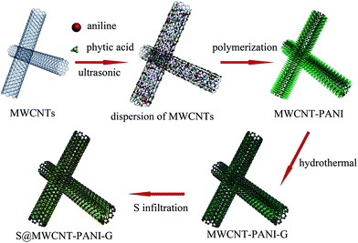
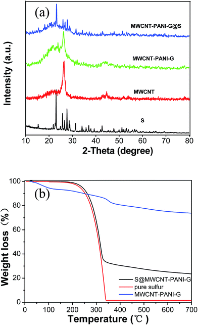
The synthetic process of the S@MWCNT–PANI–G composite is illustrated in Fig. 1. In this novel design, phytic acid and aniline were used as the gelatinizer and monomers, respectively, which were uniformly covalently attached to the walls of the MWCNTs. Polyaniline was uniformly formed on the MWCNT walls by a polymerization reaction. Subsequently the obtained MWCNT–PANI composite was then coated with thin graphene layers via hydrothermal synthesis. Finally, sulfur is encapsulated in the MWCNT–PANI–G composites by liquid infiltration and annealing treatment.Fig. 2(a) shows the XRD patterns of pure sulfur, MWCNTs, MWCNT–PANI–G and the S@MWCNT–PANI–G composite. Compared with pure MWCNT, the XRD pattern of MWCNT–PANI–G remains a strong peak at 26.5°, corresponding to the graphite (002) plane in CNTs. The broad peak centered at 21.4° is ascribed to the polyaniline.14,30 For the S@MWCNT–PANI–G composite, we can see that the characteristic peaks of element sulfur decrease significantly, indicating a fine encapsulation and good dispersion of sulfur within the MWCNT–PANI–G host.31 In order to ascertain the sulfur loading in the S@MWCNT–PANI–G composite, TGA was carried out in a nitrogen flow as shown in Fig. 2(b). The weight loss of MWCNT–PANI–G substrate before 150 °C was mainly ascribed to the elimination of adsorbed H2O, and the subsequent weight loss of 21.6 wt% after 150 °C was caused by the pyrolysis of oxygen-containing functional groups and carbonization of PANI.28,32 Because the S@MWCNT–PANI–G composite underwent a heat treatment at 220 °C for 5 h during the preparation, it did not show an obvious weight loss before 150 °C during TGA measurement. The gross sulfur content in S@MWCNT–PANI–G composite obtained directly from the TG curve is 75 wt%. After deducting the weight loss of MWCNT–PANI–G substrate (7 wt% for the composite at the temperature range of 150–750 °C), the exact sulfur content in the S@MWCNT–PANI–G composite was calculated to be 68 wt%.
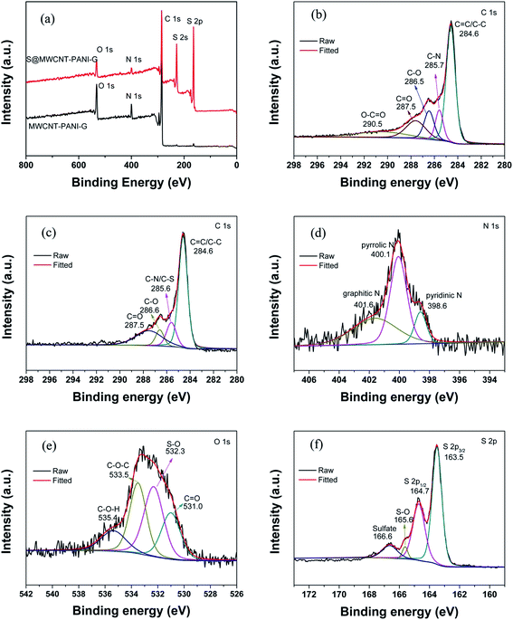
The surface characteristics of the as-prepared samples were further investigated by XPS analyses as presented in Fig. 3(a). It is apparent that three peaks at 284.4, 399.7 and 532.6 eV are observed before sulfur loading, corresponding to C 1s, N 1s and O 1s, respectively. After loading sulfur on the MWCNT–PANI–G composite, there are additional two peaks detected at 228.2 and 164.5 eV, which can be ascribed to S 2s and S 2p. Fig. 3(b) shows the high-resolution C 1s spectrum of MWCNT–PANI–G. We can see that five kinds of peaks centered at 284.6, 285.7, 286.5, 287.5 and 290.5 eV are attributed to the C![[double bond, length as m-dash]](https://www.rsc.org/images/entities/char_e001.gif) C/C–C, C–N, C–O, C
C/C–C, C–N, C–O, C![[double bond, length as m-dash]](https://www.rsc.org/images/entities/char_e001.gif) O and O–C
O and O–C![[double bond, length as m-dash]](https://www.rsc.org/images/entities/char_e001.gif) O functional groups,33,34 respectively. The high-resolution C 1s spectrum (Fig. 3(c)) of S@MWCNT–PANI–G composite has a peak centered at 285.6 eV, which is ascribed to the overlapped peaks of C–S and C–N bonds, revealing that the element sulfur is bonded to the MWCNT–PANI–G.35–37 This is confirmed by the O 2s spectrum shown in Fig. 3(e) with a strong peak located at 532.3 eV, which corresponds to the formation of S–O bond during the vulcanization reaction between the sulfur and host. In addition, the high-resolution N 1s spectrum (Fig. 3(d)) of S@MWCNT–PANI–G can be divided into three peaks at 398.6, 400.1 and 401.6 eV, which are ascribed to pyridinic N, pyrrolic N and graphitic N, respectively, indicating that the surface of MWCNT–PANI–G contains abundant N-doping functional groups and can improve its absorption to polysulfides, which has been demonstrated in previous report.38 Furthermore, by analyzing the S 2p spectrum in Fig. 3(f), the 2p3/2 and 2p1/2 doublet detected at 163.5 eV and 164.7 eV with a binding energy separation of 1.2 eV, further confirming the formation of C
O functional groups,33,34 respectively. The high-resolution C 1s spectrum (Fig. 3(c)) of S@MWCNT–PANI–G composite has a peak centered at 285.6 eV, which is ascribed to the overlapped peaks of C–S and C–N bonds, revealing that the element sulfur is bonded to the MWCNT–PANI–G.35–37 This is confirmed by the O 2s spectrum shown in Fig. 3(e) with a strong peak located at 532.3 eV, which corresponds to the formation of S–O bond during the vulcanization reaction between the sulfur and host. In addition, the high-resolution N 1s spectrum (Fig. 3(d)) of S@MWCNT–PANI–G can be divided into three peaks at 398.6, 400.1 and 401.6 eV, which are ascribed to pyridinic N, pyrrolic N and graphitic N, respectively, indicating that the surface of MWCNT–PANI–G contains abundant N-doping functional groups and can improve its absorption to polysulfides, which has been demonstrated in previous report.38 Furthermore, by analyzing the S 2p spectrum in Fig. 3(f), the 2p3/2 and 2p1/2 doublet detected at 163.5 eV and 164.7 eV with a binding energy separation of 1.2 eV, further confirming the formation of C![[double bond, length as m-dash]](https://www.rsc.org/images/entities/char_e001.gif) S and C–S bond.33 The peaks at 165.6 and 166.6 eV arise from the S–O bonds and sulfate species, respectively. These results indicate that the sulfur is well bonded with PANI and is chemically confined in the MWCNT–PANI–G hybrid.
S and C–S bond.33 The peaks at 165.6 and 166.6 eV arise from the S–O bonds and sulfate species, respectively. These results indicate that the sulfur is well bonded with PANI and is chemically confined in the MWCNT–PANI–G hybrid.
The morphology and microstructure of the as-prepared materials were characterized by SEM and TEM. The images were shown in Fig. 4 and 5, respectively. Fig. 4(a) shows the pristine MWCNTs with average diameter of ∼100 nm and nothing is observed on the surface of the material. While after the polymerization reaction, it can be seen from the SEM (Fig. 4(b)) and TEM images (Fig. 5(a)) of MWCNT–PANI that there is a layer of burr-like material uniformly coated on the walls of MWCNTs. The CNTs become larger than 180 nm in diameter, suggesting the thickness of the PANI coating is about 40 nm. The SEM image of the MWCNT–PANI–G is shown in Fig. 4(c); we can clearly see that thin graphene layers were coated on the MWCNT–PANI surface. At the same time, the TEM image of MWCNT–PANI–G (Fig. 5(b) and (c)) can further prove this result. Fig. 4(d) displays the SEM image of the S@MWCNT–PANI–G composite; it is hard to observe large bulk sulfur particles, which indicates that the sulfur was evenly dispersed in the MWCNT–PANI–G. The TEM image of S@MWCNT–PANI–G composite (Fig. 5(d)) and corresponding elemental mapping of carbon (Fig. 5(e)) and sulfur (Fig. 5(f)) further confirm the well-distributed sulfur in the composite.
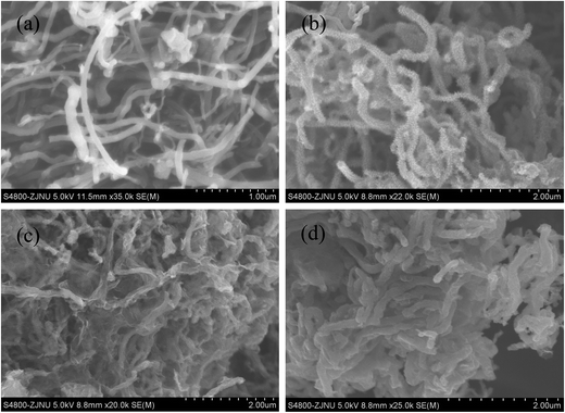 | ||
| Fig. 4 SEM images of the pristine MWCNT (a), MWCNT–PANI (b), MWCNT–PANI–G (c), and S@MWCNT–PANI–G composite (d). | ||
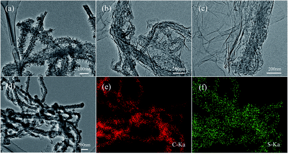 | ||
| Fig. 5 TEM images of MWCNT–PANI (a) and MWCNT–PANI–G (b and c). TEM image of the S@MWCNT–PANI–G composite (d) and corresponding elemental mapping of carbon (e) and sulfur (f) in the composite. | ||
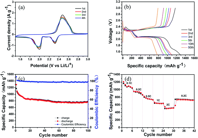
In order to investigate the electrochemical behavior of the S@MWCNT–PANI–G (68% S) composite, CV measurement was carried out and the result is shown in Fig. 6(a). During the discharge process, a pair of remarkable reduction peaks are observed at 1.99 V and 2.32 V, which correspond to the two-step reduction mechanism of sulfur. The peak at 2.32 V is assigned to the reduction of sulfur to high-order lithium polysulphides (Li2Sn, 2 < n < 8) and the peak at 1.99 V is assigned to the further reduction of the lithium polysulphides to Li2S2/Li2S, respectively. During the charge process, an oxidation peak observed at 2.46 V is attributed to the reverse oxidation of Li2S2/Li2S to elemental sulfur.39 The position and intensity of these peaks maintain stable in the subsequent scans, indicating that good electrochemical stability and reversibility.40 Fig. 6(b) displays the typical galvanostatic charge–discharge voltage profiles of the as-prepared cathode measured at a rate of 0.2C. The curves show two typical discharge voltage plateaus and one charge voltage plateau that are consistent with the redox peaks in CV curves. In the initial cycles, a low voltage plateau around 1.6–1.7 V is associated with the irreversible reductions of LiNO3 and Li2S2.41–43 It is notable that there is no significant drop in the voltage plateau during cycling, suggesting a good cycling stability.
The cycling performance of the S@MWCNT–PANI–G composite is depicted in Fig. 6(c). The S@MWCNT–PANI–G electrode with the sulfur content of 68 wt% shows a remarkable initial discharge capacity of 1290 mA h g−1 and still maintains a good reversible capacity of 784 mA h g−1 after 100 cycles at a rate of 0.2C, with a coulombic efficiency approaching 98.8%. The rate capability of the S@MWCNT–PANI–G composite is also investigated. As shown in Fig. 6(d), the reversible capacities of 1207 mA h g−1, 954 mA h g−1, 821 mA h g−1, 663 mA h g−1 and 548 mA h g−1 are obtained when cycled at 0.1C, 0.2C, 0.5C, 1C and 2C, respectively. When the current density is switched back to 0.2C, a reversible capacity of 730 mA h g−1 is retained. These results suggest that the S@MWCNT–PANI–G electrodes have an excellent cycling stability and rate capability. The remarkable electrochemical performance of S@MWCNT–PANI–G electrode is attributed to the following reasons. First, the intertwined MWCNTs as the supporting backbone in the elaborately designed structure can guarantee the structural stability of composite and provide effective conductive paths for ion and electron transfer. Second, the PANI coating can significantly restrict the dissolution of polysulfides. The abundant N-doping functional groups from PANI have strong ability to physically and chemically absorb soluble lithium polysulfides. Third, the graphene coating as an elastic buffer can accommodate the huge volume change during the cycling process and also ensure the high conductivity of electrode. As a result, the well-designed S@MWCNT–PANI–G composite is conducive to improve the electrochemical performance in Li–S batteries.
4. Conclusion
In summary, we have demonstrated a novel strategy for the synthesis of MWCNT–PANI–G hybrid, which is composed of multiple conductive matrix and abundant N-doping functional groups. The strategy utilizes MWCNTs as the backbone, which provide multi-dimensional electronic transfer path to reduce the resistance. The PANI coating serves as a conductive sorbent to minimize the polysulfide dissolution and the graphene layers can facilitate the transport of ions/electrons. Meanwhile, the sulfur can be homogenously encapsulated and covalently bonded to MWCNT–PANI–G hybrid, as confirmed by various characterization techniques. Such elaborately designed materials with unique structure can be employed as an efficient sulfur host for Li–S batteries which have exhibited high initial specific capacity (1290 mA h g−1 at 0.2C in the first cycle), good cycling stability (784 mA h g−1 at 0.2C after 100 cycles) and excellent rate capability (548 mA h g−1 at 2C, 730 mA h g−1 when returned to 0.2C). In addition, the synthesis procedure is simple, and it might have certain significance to the industrial application.Acknowledgements
This work is supported by the National Science Foundation of China (No. 11574273), and the Natural Science Foundation of Zhejiang Province (No. LY15B030003 and LY16B030003).References
- R. Fang, S. Zhao, P. Hou, M. Cheng, S. Wang, H. Cheng, C. Liu and F. Li, Adv. Mater., 2016, 28, 3374–3382 CrossRef CAS PubMed.
- H. H. Deng, L. B. Yao, Q. A. Huang, Q. M. Su, J. Zhang and G. H. Du, Mater. Res. Bull., 2016, 84, 218–224 CrossRef CAS.
- A. Manthiram, Y. Fu, S. Chung, C. Zu and Y. Su, Chem. Rev., 2014, 114, 11751–11787 CrossRef CAS PubMed.
- R. Cao, W. Xu, D. Lv, J. Xiao and J. Zhang, Adv. Energy Mater., 2015, 5, 1402273–1402296 CrossRef.
- M. Agostini, B. Scrosati and J. Hassoun, Adv. Energy Mater., 2015, 5, 1500481–1500487 CrossRef.
- Z. Zhang, Y. Lai, Z. Zhang, K. Zhang and J. Li, Electrochim. Acta, 2014, 129, 55–61 CrossRef CAS.
- M. A. Pope and I. A. Aksay, Adv. Energy Mater., 2015, 5, 1500124–1500146 CrossRef.
- S. Evers and L. F. Nazar, Acc. Chem. Res., 2012, 46, 1135–1143 CrossRef PubMed.
- M. Wang, H. Zhang, W. Zhou, X. Yang, X. Li and H. Zhang, J. Mater. Chem. A, 2016, 4, 1653–1662 CAS.
- J. Zhang, J. Xiang, Z. Dong, Y. Liu, Y. Wu, C. Xu and G. H. Du, Electrochim. Acta, 2014, 116, 146–151 CrossRef CAS.
- J. Guo, J. Zhang, F. Jiang, S. Zhao, Q. Su and G. H. Du, Electrochim. Acta, 2015, 176, 853–860 CrossRef CAS.
- J. Zhang, Z. Dong, X. Wang, X. Zhao, J. Tu, Q. Su and G. H. Du, J. Power Sources, 2014, 270, 1–8 CrossRef CAS.
- G. Zhou, S. Pei, L. Li, D. Wang, S. Wang, K. Huang, L. Yin, F. Li and H. Cheng, Adv. Mater., 2014, 26, 625–631 CrossRef CAS PubMed.
- L. Xiao, Y. Cao, J. Xiao, B. Schwenzer, M. H. Engelhard, L. V. Saraf, Z. M. Nie, G. J. Exarhos and J. Liu, Adv. Mater., 2012, 24, 1176–1181 CrossRef CAS PubMed.
- Z. Dong, J. Zhang, X. Zhao, J. Tu, Q. Su and G. Du, RSC Adv., 2013, 3, 24914–24917 RSC.
- Y. Cao, X. Li, M. Zheng, M. Yang, X. Yang and Q. Dong, Electrochim. Acta, 2016, 192, 467–474 CrossRef CAS.
- W. Li, Q. Zhang, G. Zheng, Z. Seh, H. Yao and Y. Cui, Nano Lett., 2013, 13, 5534–5540 CrossRef CAS PubMed.
- Y. Yang, G. Yu, J. Cha, H. Wu, M. Vosgueritchian, Y. Yao, Z. Bao and Y. Cui, ACS Nano, 2011, 5, 9187–9193 CrossRef CAS PubMed.
- X. Chen, Z. Xiao, X. Ning, Z. Liu, Z. Yang, C. Zou, S. Wang, X. Chen, Y. Chen and S. Huang, Adv. Energy Mater., 2014, 4, 1301988–1301996 CrossRef.
- J. He, Y. Chen, P. Li, F. Fu, Z. Wang and W. Zhang, J. Mater. Chem. A, 2015, 3, 18605–18610 CAS.
- Z. W. Seh, W. Li, J. Cha, G. Zheng, Y. Yang, M. T. McDowell, P. C. Hsu and Y. Cui, Nat. Commun., 2013, 4, 1331–1337 CrossRef PubMed.
- Z. Zhang, Q. Li, S. Jiang, K. Zhang, Y. Lai and J. Li, Chem.–Eur. J., 2015, 21, 1343–1349 CrossRef CAS PubMed.
- S. Wang, Z. Yang, H. Zhang, H. Tan, J. Yu and J. Wu, Electrochim. Acta, 2013, 106, 307–311 CrossRef CAS.
- B. Campbell, J. Bell, H. H. Bay, Z. Favors, R. Ionescu, C. S. Ozkan and M. Ozkan, Nanoscale, 2015, 7, 7051–7055 RSC.
- L. Ma, H. Zhuang, S. Wei, K. E. Hendrickson, M. S. Kim, G. Cohn, R. G. Hennig and L. A. Archer, ACS Nano, 2015, 10, 1050–1059 CrossRef PubMed.
- M. N. Hyder, R. Kavian, Z. Sultana, K. Saetia, P. Y. Chen, S. W. Lee, Y. Shao-Horn and P. T. Hammond, Chem. Mater., 2014, 26, 5310–5318 CrossRef CAS.
- J. Yan, B. Li and X. B. Liu, Nano Energy, 2015, 18, 245–252 CrossRef CAS.
- G. Li, G. Li, S. Ye and X. Gao, Adv. Energy Mater., 2012, 2, 1238–1245 CrossRef CAS.
- Y. Xu, K. Sheng, C. Li and G. Shi, ACS Nano, 2010, 4, 4324–4330 CrossRef CAS PubMed.
- P. Y. Chen, N. M. D. Courchesne, M. N. Hyder, J. F. Qi, A. M. Belcher and P. T. Hammond, RSC Adv., 2015, 5, 37970–37977 RSC.
- C. Xu, Y. Wu, X. Zhao, X. Wang, G. Du, J. Zhang and J. Tu, J. Power Sources, 2015, 275, 22–25 CrossRef CAS.
- Z. Zhang, H. Jing, S. Liu, G. Li and X. Gao, J. Mater. Chem. A, 2015, 3, 6827–6834 CAS.
- Z. Wang, Y. Dong, H. Li, Z. Zhao, H. Wu, C. Hao, S. Liu, J. Qiu and X. Lou, Nat. Commun., 2014, 5, 5002–5010 CrossRef CAS PubMed.
- P. Chen, J. Yang, S. Li, Z. Wang, T. Xiao, Y. Qian and S. Yu, Nano Energy, 2013, 2, 249–256 CrossRef CAS.
- G. Li, J. Sun, W. Hou, S. Jiang, Y. Huang and J. Geng, Nat. Commun., 2016, 7, 10601–10611 CrossRef CAS PubMed.
- C. Zu and A. Manthiram, Adv. Energy Mater., 2013, 3, 1008–1012 CrossRef CAS.
- S. Yuan, J. Bao, L. Wang, Y. Xia, D. G. Truhlar and Y. Wang, Adv. Energy Mater., 2015, 6, 1501733–1501742 CrossRef.
- J. Chen, R. Yuan, J. Feng, Q. Zhang, J. Huang, G. Fu, M. Zheng, B. Ren and Q. Dong, Chem. Mater., 2015, 27, 2048–2055 CrossRef CAS.
- Y. Liu, J. Zhang, X. Liu, J. Guo, L. Pan, H. Wang, Q. Su and G. Du, Mater. Lett., 2014, 133, 193–196 CrossRef CAS.
- Y. Liu, J. Guo, J. Zhang, Q. Su and G. Du, Appl. Surf. Sci., 2015, 324, 399–404 CrossRef CAS.
- N. Ding, S. W. Chien, T. A. Hor, Z. Liu and Y. Zong, J. Power Sources, 2014, 269, 111–116 CrossRef CAS.
- S. zhang, J. Electrochem. Soc., 2012, 159, A920–A923 CrossRef CAS.
- S. zhang, J. Power Sources, 2016, 322, 99–105 CrossRef CAS.
| This journal is © The Royal Society of Chemistry 2017 |

