 Open Access Article
Creative Commons Attribution 3.0 Unported Licence
In situ synthesis of homogeneous Ce2S3/MoS2 composites and their electrochemical performance for lithium ion batteries
Baoting Houa,
Xinlu Wang a,
Jinxian Wang*a,
Jing Yaoa,
Hongbo Zhanga,
Wensheng Yua,
Guixia Liu
 a,
Xiangting Donga and
Limin Wangb
aKey Laboratory of Applied Chemistry and Nanotechnology at Universities of Jilin Province, Changchun University of Science and Technology, Changchun 130022, China. E-mail: wjx87@sina.com
bState Key Laboratory of Rare Earth Resource Utilization, Changchun Institute of Applied Chemistry, CAS, Changchun, 130022, China
First published on 20th January 2017
Abstract
Homogeneous Ce2S3/MoS2 composite have been fabricated via an in situ sulfurization method and their structure, morphology and electrochemical properties are researched systematically for the first time. Ce2S3/MoS2 composite present spherical secondary particles of 0.5–1 μm in diameter. The cycling performance and rate property of Ce2S3/MoS2 composite are better than those of Ce2S3 and MoS2 as anode materials for lithium ion batteries. Among them, Ce2S3/MoS2 composite (cationic ratio of Ce![[thin space (1/6-em)]](https://www.rsc.org/images/entities/char_2009.gif) :
:![[thin space (1/6-em)]](https://www.rsc.org/images/entities/char_2009.gif) Mo in 4
Mo in 4![[thin space (1/6-em)]](https://www.rsc.org/images/entities/char_2009.gif) :
:![[thin space (1/6-em)]](https://www.rsc.org/images/entities/char_2009.gif) 1) have an initial discharge capacity of 225.5 mA h g−1, a coulombic efficiency of 99.1% and a reversible capacity as high as 661.7 mA h g−1, a coulombic efficiency of 99.7% after 500 cycles at a current density of 100 mA g−1 and the highest discharge capacity of 285.6 mA h g−1 at a high current density of 1000 mA g−1, showing the best cycling performance and rate capability among the as-prepared Ce2S3/MoS2 composite. The reason is that the compositing between MoS2 and Ce2S3 can maintain the stability of the structure during the charge/discharge process and the existence of Ce2S3 enhances the electrical conductivity of Ce2S3/MoS2 composite and further improves the reversible capacities and rate performance of Ce2S3/MoS2 composite.
1) have an initial discharge capacity of 225.5 mA h g−1, a coulombic efficiency of 99.1% and a reversible capacity as high as 661.7 mA h g−1, a coulombic efficiency of 99.7% after 500 cycles at a current density of 100 mA g−1 and the highest discharge capacity of 285.6 mA h g−1 at a high current density of 1000 mA g−1, showing the best cycling performance and rate capability among the as-prepared Ce2S3/MoS2 composite. The reason is that the compositing between MoS2 and Ce2S3 can maintain the stability of the structure during the charge/discharge process and the existence of Ce2S3 enhances the electrical conductivity of Ce2S3/MoS2 composite and further improves the reversible capacities and rate performance of Ce2S3/MoS2 composite.
1. Introduction
As a development of advanced electronic devices with high energy density, rechargeable lithium-ion batteries (LIBs) have been considered as effective electrochemical energy storage devices due to their advantages of high energy density, long lifespan, no memory effect, high safety and environment-friendliness.1–5 Right now, graphite, which is the main anode material for LIBs, cannot reach the increasing demands of the portable electronic device markets due to its low theoretical capacity (372 mA h g−1). MoS2 has received considerable attention as an anode material for LIBs owing to its high theoretical capacity (669 mA h g−1).6–8 Hence, numerous efforts have been made to prepare MoS2 and its electrochemical performance was studied. For example, Lou et al. prepared MoS2 microspheres consisting of few-layered nanosheets by a polystyrene template-based hydrothermal method, which show enhanced capacity retention and rate capability.9 However, low electrical conductivity and volume change during the cycling result in poor cycling and rate performance, which limit their practical application.10In recent years, some MoS2-based composite have been explored as high-performance anode materials for LIBs. Such as MoS2/carbon black,11–13 MoS2/carbon nanotube14–16 (CNT), MoS2/graphene,17–19 MoS2/carbon fiber cloth,20 MoS2/amorphous carbon,21 MoS2/SnO2,22 MoS2/Fe3O4 (ref. 23) and MoS2/TiO2 (ref. 24) and so on, indicating that improved the electrochemical performance due to it can maintain the stability of the structure during the charge/discharge process to buffer the volume change of MoS2.25
Cerium sulfide (Ce2S3) which exists in three crystal structure of α, β and γ phase has received considerable attention due to appealing special physical, thermal, mechanical, electronic, optical stability and excellent electrical conductivity.26–28 Therefore, huge efforts have been made to prepare various crystal structural Ce2S3 and their physical, chemical properties and application fields were studied. Ce2S3 is used as mainly nontoxic red pigment instead of heavy metal compounds at present. For example, Yu et al. prepared the γ-Ce2S3@SiO2 by sulfurization method with corresponding CeO2, which shows excellent thermal and acid stabilities.29
To date, the preparation and application of Ce2S3/MoS2 composite were barely explored. We prepared homogeneous Ce2S3/MoS2 composite via an in situ sulfurization method and investigated their phase structure, morphology and electrochemical performance for the first time. The homogeneous Ce2S3/MoS2 composite tested as anode materials for LIBs shown excellent electrochemical performance, including higher reversible capacity, exceptional cycle life, and good rate performance compared with Ce2S3 and MoS2.
2. Experimental section
2.1. Materials
The Cerium carbonate (Ce2(CO3)3, 99.95%, Shanghai AiBi Chemistry Preparation Co. Ltd. China), Carbon disulfide (CS2 boiling point: 46–47 °C, Tianjin Tiantai Fine Chemical Reagents Co. Ltd. China), Ammonium molybdate ((NH4)6Mo7O24·4H2O, 99%, Shanghai AiBi Chemistry Preparation Co. Ltd. China) were used as the starting materials. Acetylene black, Polyvinylidene fluoride (PVDF) and N-methyl-2-pyrrolidone (NMP) were bought from Sinopharm Chemical Reagent Co. Ltd. Electrolyte (1mol L−1 LiPF6 in ethylene carbonate/dimethyl carbonate (1![[thin space (1/6-em)]](https://www.rsc.org/images/entities/char_2009.gif) :
:![[thin space (1/6-em)]](https://www.rsc.org/images/entities/char_2009.gif) 1 v/v) solution) was purchased from Tianneng Group and counter electrode (pure lithium foil) was purchased from China Energy Lithium Co., Ltd. All chemicals were analytical grade and used as received without further purification.
1 v/v) solution) was purchased from Tianneng Group and counter electrode (pure lithium foil) was purchased from China Energy Lithium Co., Ltd. All chemicals were analytical grade and used as received without further purification.
2.2. Preparation of Ce2S3, MoS2 and homogeneous Ce2S3/MoS2 composite
An in situ sulfurization method was used for preparing homogeneous Ce2S3/MoS2 composite. The Ce2(CO3)3 and (NH4)6Mo7O24·4H2O was mixed uniformly according to cationic ratio: Ce![[thin space (1/6-em)]](https://www.rsc.org/images/entities/char_2009.gif) :
:![[thin space (1/6-em)]](https://www.rsc.org/images/entities/char_2009.gif) Mo in 6
Mo in 6![[thin space (1/6-em)]](https://www.rsc.org/images/entities/char_2009.gif) :
:![[thin space (1/6-em)]](https://www.rsc.org/images/entities/char_2009.gif) 1, 5
1, 5![[thin space (1/6-em)]](https://www.rsc.org/images/entities/char_2009.gif) :
:![[thin space (1/6-em)]](https://www.rsc.org/images/entities/char_2009.gif) 1, 4
1, 4![[thin space (1/6-em)]](https://www.rsc.org/images/entities/char_2009.gif) :
:![[thin space (1/6-em)]](https://www.rsc.org/images/entities/char_2009.gif) 1 and 3
1 and 3![[thin space (1/6-em)]](https://www.rsc.org/images/entities/char_2009.gif) :
:![[thin space (1/6-em)]](https://www.rsc.org/images/entities/char_2009.gif) 1. The mixture that was contained in graphite boat was introduced into high temperature furnace. After flushing with high-purity Ar gas at room temperature, the graphite boat was heated and held at 950 °C for 2 h. CS2 was introduced into the quartz tube by passing Ar carrier gas through a bubbler containing liquid CS2. To minimize the carbon or sulfide from the thermal dissociation of CS2 deposition on the sample, CS2 was introduced only when the furnace was heated over 500 °C. After the desired reaction time at 950 °C, CS2 was withdrawn before the furnace was cooled to 500 °C. The as-synthesized Ce2S3/MoS2 composite with the cationic ratio of Ce
1. The mixture that was contained in graphite boat was introduced into high temperature furnace. After flushing with high-purity Ar gas at room temperature, the graphite boat was heated and held at 950 °C for 2 h. CS2 was introduced into the quartz tube by passing Ar carrier gas through a bubbler containing liquid CS2. To minimize the carbon or sulfide from the thermal dissociation of CS2 deposition on the sample, CS2 was introduced only when the furnace was heated over 500 °C. After the desired reaction time at 950 °C, CS2 was withdrawn before the furnace was cooled to 500 °C. The as-synthesized Ce2S3/MoS2 composite with the cationic ratio of Ce![[thin space (1/6-em)]](https://www.rsc.org/images/entities/char_2009.gif) :
:![[thin space (1/6-em)]](https://www.rsc.org/images/entities/char_2009.gif) Mo = 6
Mo = 6![[thin space (1/6-em)]](https://www.rsc.org/images/entities/char_2009.gif) :
:![[thin space (1/6-em)]](https://www.rsc.org/images/entities/char_2009.gif) 1, 5
1, 5![[thin space (1/6-em)]](https://www.rsc.org/images/entities/char_2009.gif) :
:![[thin space (1/6-em)]](https://www.rsc.org/images/entities/char_2009.gif) 1, 4
1, 4![[thin space (1/6-em)]](https://www.rsc.org/images/entities/char_2009.gif) :
:![[thin space (1/6-em)]](https://www.rsc.org/images/entities/char_2009.gif) 1 and 3
1 and 3![[thin space (1/6-em)]](https://www.rsc.org/images/entities/char_2009.gif) :
:![[thin space (1/6-em)]](https://www.rsc.org/images/entities/char_2009.gif) 1 were named as C6M1, C5M1, C4M1 and C3M1 for short. For the sulfurization method used for preparing Ce2S3 and MoS2, the conditions were similar to those for the fabrication of the Ce2S3/MoS2 composite. The chemical reactions for the preparation of Ce2S3 and MoS2 can be described by the chemical reaction (1) and (2):
1 were named as C6M1, C5M1, C4M1 and C3M1 for short. For the sulfurization method used for preparing Ce2S3 and MoS2, the conditions were similar to those for the fabrication of the Ce2S3/MoS2 composite. The chemical reactions for the preparation of Ce2S3 and MoS2 can be described by the chemical reaction (1) and (2):| 2Ce2(CO3)3 + 3CS2 → 2Ce2S3 + 9CO2 | (1) |
| 2(NH4)6Mo7O24·4H2O + 21CS2 → 14MoS2 + 12NH3 + 14H2O + 21CO2 + 7S2 | (2) |
2.3. Characterization methods
The crystal structure of as-prepared materials was studied by powder X-ray diffractometry (XRD, Dandong Tongda TD-3000) with the Cu Kα (40 kV, 30 mA) radiation (λ = 1.5406 Å) over the range of 10–90° at a scanning speed of 0.01° s−1. The particle morphology and size of the as-prepared products were characterized by a scanning electron microscope (SEM, JMS-7610F, JEOL, Japan). Chemical element composition and element spatial distribution analysis was performed with energy dispersive X-ray spectrum (EDX) spectrometer (OXFORDX-Max).2.4. Electrochemical measurements
The anodes were manufactured using the above-obtained materials as the active materials, acetylene black as conductive additive, and PVDF as binder in the mass ratio of 80![[thin space (1/6-em)]](https://www.rsc.org/images/entities/char_2009.gif) :
:![[thin space (1/6-em)]](https://www.rsc.org/images/entities/char_2009.gif) 10
10![[thin space (1/6-em)]](https://www.rsc.org/images/entities/char_2009.gif) :
:![[thin space (1/6-em)]](https://www.rsc.org/images/entities/char_2009.gif) 10 dissolved in NMP. Then the mixed slurry was coated onto the Cu foil and dried in a vacuum at 120 °C for 24 h. Then the film was cut into discs with the loading mass of about 2 mg cm−2. The electrochemical performances of the samples were tested by half cells assembled in an argon-filled glove box (H2O, O2 content < 1 ppm). Electrochemical measurements were carried out using 2032-type half cells with a pure lithium foil as the counter electrode, Celgard 2320 as the separator, and 1 mol L−1 LiPF6 in ethylene carbonate/dimethyl carbonate (1
10 dissolved in NMP. Then the mixed slurry was coated onto the Cu foil and dried in a vacuum at 120 °C for 24 h. Then the film was cut into discs with the loading mass of about 2 mg cm−2. The electrochemical performances of the samples were tested by half cells assembled in an argon-filled glove box (H2O, O2 content < 1 ppm). Electrochemical measurements were carried out using 2032-type half cells with a pure lithium foil as the counter electrode, Celgard 2320 as the separator, and 1 mol L−1 LiPF6 in ethylene carbonate/dimethyl carbonate (1![[thin space (1/6-em)]](https://www.rsc.org/images/entities/char_2009.gif) :
:![[thin space (1/6-em)]](https://www.rsc.org/images/entities/char_2009.gif) 1 v/v) solution as the electrolyte. The charge–discharge performance was performed by battery testing system (BTS-5 V/10 mA, Neware Technology Co. Ltd. China) with a cutoffs potential of 0.01–3.0 V versus Li/Li+. Electrochemical impedance spectra (EIS) and cyclic voltammetry galvanostatic cycling (CV) measurements were evaluated on an electrochemical workstation (CHI-760D, Shanghai Chenhua Instrument Co. Ltd. China). For the CV measurements, the voltage was fixed between 0.01 V and 3.0 V and the scanning rate was fixed at 0.1 mV s−1. For the EIS measurements, the amplitude of the alternating current signal to the cells was 10 mV and the frequency was between 100 kHz and 0.01 Hz.
1 v/v) solution as the electrolyte. The charge–discharge performance was performed by battery testing system (BTS-5 V/10 mA, Neware Technology Co. Ltd. China) with a cutoffs potential of 0.01–3.0 V versus Li/Li+. Electrochemical impedance spectra (EIS) and cyclic voltammetry galvanostatic cycling (CV) measurements were evaluated on an electrochemical workstation (CHI-760D, Shanghai Chenhua Instrument Co. Ltd. China). For the CV measurements, the voltage was fixed between 0.01 V and 3.0 V and the scanning rate was fixed at 0.1 mV s−1. For the EIS measurements, the amplitude of the alternating current signal to the cells was 10 mV and the frequency was between 100 kHz and 0.01 Hz.
3. Results and discussion
3.1. Structure and morphology characterization of Ce2S3, MoS2 and Ce2S3/MoS2 composite
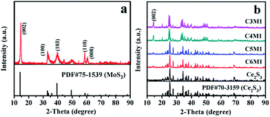
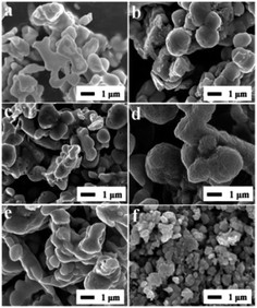
The XRD patterns of Ce2S3, MoS2 and Ce2S3/MoS2 composite are shown in Fig. 1. XRD patterns of the MoS2 are shown in Fig. 1a. The distinctive (002), (100), (103), (110) and (008) diffraction peaks indicate that MoS2 has a hexagonal structure (JCPDS card no. 75-1539) with space group P63/mmc. The XRD patterns in Fig. 1b manifest the phase structure of Ce2S3 and Ce2S3/MoS2 composite. All of the diffraction peaks in the XRD patterns clearly for Ce2S3 can be indexed to space group, Pnma (JCPDS card no. 70-3159), indicative of perfect crystalline structure of orthorhombic Ce2S3. For the structure of the Ce2S3/MoS2 composite, despite the differences in their MoS2 concentrations, all the peaks could be indexed to the orthorhombic structure Ce2S3 and hexagonal structure MoS2. The sharp peaks suggest all of products being highly crystallized. In addition, there is no shift of peaks that can be detected in all of XRD patterns of Ce2S3/MoS2 composite, indicating that the compositing process has no impact on structure of Ce2S3. The results mentioned above indicate that MoS2 is successfully composited in the Ce2S3.The SEM images in Fig. 2a–f show the morphology of Ce2S3, MoS2 and Ce2S3/MoS2 composite, which can be observed that obvious changes of morphology of Ce2S3/MoS2 composite have taken place compared to Ce2S3 and MoS2, presenting spherical secondary particles of 0.5–1 μm in diameter. Among them, C4M1 have the largest particle size, which aggregate each other to form spherical secondary particles of 1–1.5 μm in diameter with flower-like structure on the surface of particle. To further confirm the element composition and element spatial distribution of Ce2S3/MoS2 composite, the EDX spectrum and spatial elemental mappings of C4M1 are demonstrated in Fig. 3, which proves that the Ce2S3/MoS2 composite cover the elements S Kα1, Mo Lα1, and Ce Lα1 and the homogeneous distribution of all these elements and the Pt peaks in the spectrum come from platinum conductive film plated on the surface of the sample for SEM observation. All the results mentioned above indicate that MoS2 is successfully composited in the Ce2S3.
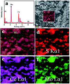 | ||
| Fig. 3 The chemical element composition and elemental mappings of C4M1 composite. (a) EDX spectrum, (b and c) SEM images and (d–f) Elemental mappings of C4M1. | ||
3.2. Electrochemical performance of Ce2S3, MoS2 and Ce2S3/MoS2 composite
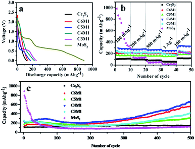
The voltage profiles of Ce2S3, MoS2 and Ce2S3/MoS2 composite electrodes during the first cycle at a current density of 100 mA g−1 with voltage cutoffs of 0.01 V and 3.0 V versus Li/Li+ are shown in Fig. 4a. During initial lithiation process, two plateaus located at 1.2 V and 0.7 V are observed in voltage profiles of MoS2, corresponding to the discharge capacity of 887.5 mA h g−1 and 88.4% coulombic efficiency. The first plateau corresponds to the intercalation of Li-ions to MoS2 electrodes materials, and the second plateau is ascribed to the phase conversion reaction of MoS2.18,19 Remarkably, two plateaus located at 1.2 V and 0.7 V are also observed in voltage profiles of Ce2S3/MoS2 composite during initial lithiation process, corresponding to the discharge capacities of 139.8, 173.9, 225.5 and 251.5 mA h g−1 and 86.8%, 82.5%, 99.1% and 84.2% coulombic efficiency, which can be ascribed to the intercalation of Li-ions to Ce2S3/MoS2 composite electrodes and phase conversion reaction possibly. Overall, initial discharge capacity of composite shows upward trend with increasing content of MoS2 in composite, which can attribute to the reason that is MoS2 exhibits high Li storage capacity (669 mA h g−1)6–8 that is much higher than that of Ce2S3. So, MoS2 can provide a high charge/discharge capacity for composite electrode materials. For voltage profiles of Ce2S3 electrode, a sloping curve is observed and no clearly potential plateau can be detected in initial lithiation process. The discharge capacity is 121.5 mA h g−1 at a current density of 100 mA g−1, corresponding to a 76% coulombic efficiency.In addition, Ce2S3/MoS2 composite electrodes exhibit much better rate capability compared to Ce2S3 and MoS2 electrodes operated at various current density between 100 mA g−1 and 1000 mA g−1 (Fig. 4b). It can be found that the discharge capacity remains stable and decreases regularly with the increased current density. After each 10 cycles at high current density of 1000 mA g−1, the average reversible capacities are about 81, 213, 187, 286, 202 and 23 mA h g−1 for Ce2S3, C6M1, C5M1, C4M1, C3M1 and MoS2 electrodes, implying that the rate cycling stability of Ce2S3/MoS2 composite electrodes is excellent. Among the composite, C4M1 shows perfect capacity retention and the highest discharge capacity at high current density of 1000 mA g−1. Remarkably, when the current density is got back to 100 mA g−1, the discharge capacity of Ce2S3/MoS2 composite can be recovered (even a little higher than the original capacity at 100 mA g−1), which shows the compositing between MoS2 and Ce2S3 enhance the structure stability of Ce2S3/MoS2 composite at various current density.
The cycling performance is an important factor to determine the practical applications of an electrode material in practical battery. The typical cycle performance of Ce2S3, MoS2 and Ce2S3/MoS2 composite electrodes cycling at a current density of 100 mA g−1 in the voltage range of 0.01–3.0 V are shown in Fig. 4c. After being charged/discharged at a current density of 100 mA g−1 for 500 cycles, the MoS2 electrode shows only capacity retention of 11.22% (vs. to the first discharge capacity). The reason why MoS2 shows high degradation rate is that MoS2 with Li reaction at a low voltage range suffers from cracking and crumbling due to their vast volume expansion/contraction during repeated charge/discharge process, which leads to a significant capacity fading by loss of inter-particle contact in the electrode. In addition, Li2S that is the product of conversion reaction can react with the electrolyte to form a thick gel-like polymeric layer, which restrain successive lithiation and de-lithiation reaction during cycling resulting in a poor cycle stability and a low rate capability.25 Interestingly, the Ce2S3 electrode did not go through capacity fading at current density of 100 mA g−1. Instead, capacity at the 500th cycle is 24.4% higher than the capacity at the 1st cycle, which shows that Ce2S3 exhibits excellent structure stability during charge/discharge process. Remarkably, for the Ce2S3/MoS2 composite electrodes, capacity at the 500th cycle is 459.2, 306.3, 661.7 and 414.6 mA h g−1 at current density of 100 mA g−1, respectively, which are higher than the capacity at the 1st cycle. Further studies need to be conducted to analyze the reasons for this phenomenon. The results show that the cycle performance of Ce2S3/MoS2 composite, especially, C4M1 exhibits the most excellent cycling performance and the highest discharge capacity compared with Ce2S3 and MoS2 electrodes. One of reason is that the compositing between MoS2 and Ce2S3 can enhance the structure stability during the charge/discharge process. On the other hand, exists of Ce2S3 can enhance the electrical conductivity of electrodes materials, which can be detected in electrochemical impedance spectra of Ce2S3, MoS2 and Ce2S3/MoS2 composite in Fig. 5a.
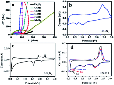 | ||
| Fig. 5 (a) Electrochemical impedance spectra (EIS) of Ce2S3, MoS2 and Ce2S3/MoS2 composite. (b–d) CV curves of MoS2, Ce2S3 and the C4M1. | ||
To analyze the lithium diffusion constant, EIS measurements were performed. All Nyquist plots are shown in Fig. 5a. Electrochemical impedance spectra of all of the samples show a compressed semicircle in the high-to-medium frequency region and a straight line in the low frequency region.30 The semicircle corresponds to the complex charge transfer the solid electrolyte interface (SEI) formed on the electrodes surface. The inclined line is attributed to the Warburg impedance and could be responsible for the lithium ion diffusion in the Ce2S3, MoS2 and Ce2S3/MoS2 composite, standing for the resistance between the electrolyte and the active material. The diameter of the semicircle in high frequency range is smaller for Ce2S3/MoS2 composite and the Warburg component of the spectra of this system has a bigger slope compared with Ce2S3 and MoS2. Apparently, the charge transfer resistance of C4M1 (58.28 Ω) is much lower than that of Ce2S3 (101.54 Ω), C6M1 (74.37 Ω), C5M1 (105.46 Ω), C3M1 (78.61 Ω) and MoS2 (150.26 Ω), which could indicate the enhanced charge transfer and lithium ion conduction in C4M1 particles, which agrees with the charge–discharge curves, and could be one of the main reason of the good cycling performance and rate performance of C4M1.
The CV curves of the Ce2S3, MoS2 and C4M1 at a scanning rate of 0.1 mV s−1 are shown in Fig. 5b–d. For CV curve of MoS2, in the first cathodic sweep, two peaks at 1.2 and 0.7 V were observed. The first peak at 1.2 V was related to the lithium insertion reaction that led to the formation of LixMoS2. Also, the second peak at 0.7 V is attributable to a conversion reaction of MoS2,18,19,31,32 which can be described as MoS2 + 4Li → Mo + 2Li2S. There is an oxidation peak at 2.2 V in the first anodic sweep, corresponding to the oxidation of Mo to form MoS2. The lithium storage mechanism of MoS2 electrode can be described by the electrochemical conversion reaction25 (3)–(5):
| MoS2 + xLi → LixMoS2 | (3) |
| LixMoS2 + (4 − x)Li → Mo + 2Li2S | (4) |
| Mo + 2Li2S ↔ Mo + 2S + 4Li | (5) |
For CV curve of the Ce2S3, in the first cathodic scan, two peaks at 2.1 and 1.72 V are observed, maybe corresponding to the formation of LixCe2S3 phase and the reduction process of Ce4+ → Ce3+ which fits with standard electrode potential (1.72 V), respectively. During the first anodic sweep, the electrode exhibits two peaks at 1.8 and 2.336 V correspond to de-lithiation back to orthorhombic Ce2S3 and oxidation process of Ce → Ce3+ which corresponds to standard electrode potential (2.336 V), respectively. The formation of Ce during reduction process of electrode materials can improve the conductivity of the electrode. The lithium storage mechanism of Ce2S3 electrode may be described by the electrochemical conversion reaction (6)–(8):
| Ce2S3 + xLi → LixCe2S3 | (6) |
| LixCe2S3 + (3 − x)Li → 2Ce + 3/2Li2S | (7) |
| Ce + 3/2Li2S ↔ Ce + 3/2S + 3Li | (8) |
For CV curves of the C4M1, it is clear that the CV curve of the first cycle is the same as those of subsequent cycles, especially for the charge branch. In the first cathodic sweep, four peaks at 0.7, 1.2, 1.72 and 2.1 V were observed. The peaks at 1.2 and 0.7 V correspond to reduction peaks of MoS2 in composite and peaks at 1.72 and 2.1 V correspond to reduction peaks of Ce2S3 in composite, respectively. In the first anodic sweep, three peaks at 1.8, 2.2 and 2.336 V were observed. The peak at 2.2 V corresponds to oxidation peak of MoS2 in composite and peaks at 1.8 and 2.336 V correspond to oxidation peaks of Ce2S3 in composite, respectively. In the second and third cycle, both the intensity and position of reduction and oxidation peaks is decreasing and shifting, respectively. It can be ascribed to the polarization of the electrode in the first cycle. It is noteworthy that after the first cycle, the CV curves almost overlapped, suggesting a good reversibility of C4M1.
4. Conclusions
An in situ sulfurization method has been successfully applied to fabricate homogeneous Ce2S3/MoS2 composite and their phase structure, morphology, element composition and distribution and electrochemical properties are researched systematically by XRD, SEM, EDX and electrochemical measurements for the first time. Results show that Ce2S3/MoS2 composite present spherical secondary particles of 0.5–1 μm in diameter. The cycling performance and rate property of Ce2S3/MoS2 composite are better than those of Ce2S3 and MoS2 as anode materials for lithium ion batteries. The electrochemical performance of MoS2 and Ce2S3 has been improved after compositing. It is found that C4M1 has the best electrochemical properties, which has an initial discharge capacity of 225.5 mA h g−1, coulombic efficiency of 99.1% and a reversible capacity as high as 661.7 mA h g−1, coulombic efficiency of 99.7% after 500 cycles at a current density of 100 mA g−1 and the highest discharge capacity of 285.6 mA h g−1 at a high current density of 1000 mA g−1. The enhanced cycling stability and rate performance of C4M1 could be attributed to the structure stabilization and the enhanced electrical conductivity of C4M1. The strategy in this study not only represents a promising avenue for developing high-performance Ce2S3/MoS2 composite, but also can be easily extended to the fabrication of other anode and cathode materials for next-generation LIBs.Acknowledgements
This research has been supported by the Natural Science Foundation of Jilin Province (No. 20170101128JC), Ph.D. Programs Foundation of the Ministry of Education of China (20102216110002, 20112216120003), the Science and Technology Planning Project of Changchun City (No. 2013064).References
- A. Vu, Y. Q. Qian and A. Stein, Adv. Energy Mater., 2012, 2, 1056–1085 CrossRef CAS.
- J. B. Goodenough and K. Youngsik, J. Mater. Chem., 2009, 22, 587–603 CrossRef.
- V. Etacheri, R. Marom, R. Elazari, G. Salitra and D. Aurbach, Energy Environ. Sci., 2011, 4, 3243–3262 CAS.
- B. Dunn, H. Kamath and J. M. Tarascon, Science, 2011, 334, 928–935 CrossRef CAS PubMed.
- S. M. Liu, J. X. Wang, J. W. Wang, F. F. Zhang, F. Liang and L. M. Wang, CrystEngComm, 2014, 16, 814–819 RSC.
- H. H. Wang, H. Kim and J. Cho, Nano Lett., 2011, 11, 4826–4830 CrossRef PubMed.
- J. Xiao, D. Choi, L. Cosimbescu, P. Koech, J. Liu and J. P. Lemmon, Chem. Mater., 2010, 22, 4522–4524 CrossRef CAS.
- C. N. R. Rao, K. Gopalakrishnan and U. Maitra, ACS Appl. Mater. Interfaces, 2015, 7, 7809–7832 CAS.
- S. Ding, D. Zhang, J. S. Chen and X. W. Lou, Nanoscale, 2012, 4, 95–98 RSC.
- Q. C. Pan, Y. G. Huang, H. Q. Wang, G. H. Yang, L. C. Wang, J. Chen and Q. Y. Li, Electrochim. Acta, 2016, 197, 50–57 CrossRef CAS.
- C. F. Zhang, H. B. Wu, Z. P. Guo and X. W. Lou, Electrochem. Commun., 2012, 20, 7–10 CrossRef CAS.
- H. Li, L. Ma, W. X. Chen and J. M. Wang, Mater. Lett., 2009, 63, 1363–1365 CrossRef CAS.
- K. Chang, W. Chen, L. Ma, H. Li, H. Li, F. Huang, Z. Xu, Q. Zhang and J. Y. Lee, J. Mater. Chem., 2011, 21, 6251–6257 RSC.
- S. Ding, J. S. Chen and X. W. Lou, Chem.–Eur. J., 2011, 17, 13142–13145 CrossRef CAS PubMed.
- S. K. Park, S. H. Yu, S. Woo, B. Quan, D. C. Lee, M. K. Kim, Y. E. Sung and Y. Piao, Dalton Trans., 2013, 42, 2399–2405 RSC.
- S. Wang, X. Jiang, H. Zheng, H. Wu, S. J. Kim and C. Feng, Nanosci. Nanotechnol. Lett., 2012, 4, 378–383 CrossRef CAS.
- Y. G. Guo, X. Zhou and L. j. Wan, Chem. Commun., 2013, 49, 1838–1840 RSC.
- K. Chang and W. Chen, ACS Nano, 2011, 5, 4720–4728 CrossRef CAS PubMed.
- K. Chang and W. Chen, Chem. Commun., 2011, 47, 4252–4254 RSC.
- C. Wang, W. Wan, Y. Huang, J. Chen, H. H. Zhou and X. X. Zhang, Nanoscale, 2014, 6, 5351–5358 CAS.
- K. Chang, W. Chen, L. Ma, H. Li, H. Li, F. Huang, Z. Xu, Q. Zhang and J. Y. Lee, J. Mater. Chem., 2011, 21, 6251–6257 RSC.
- L. Ma, X. Zhou, L. Xu, X. Xu and L. Zhang, Nano, 2016, 11, 1650023–1650028 CrossRef CAS.
- B. Song, X. Tang, L. Lu and J. Xue, Small, 2014, 10, 1536–1543 CrossRef PubMed.
- W. Zhuang, L. C. Li, J. H. Zhu, R. An, L. H. Lu, X. H. Lu, X. B. Wu and H. J. Ying, ChemElectroChem, 2015, 2, 374–381 CrossRef CAS.
- X. D. Xu, W. Liu, Y. Kim and J. Cho, Nano Today, 2014, 9, 604–630 CrossRef CAS.
- T. Takeshita, K. A. Gschneidner Jr and B. J. Beaudry, J. Appl. Phys., 1985, 57, 4633–4637 CrossRef CAS.
- C. M. Forster and W. B. White, J. Am. Ceram. Soc., 1997, 80, 273–276 CrossRef.
- C. M. Forster and W. B. White, Mater. Res. Bull., 2006, 41, 448–454 CrossRef CAS.
- S. Yu, D. Wang, Y. Liu, Z. Li, X. Zhang, Y. Wang, X. Wang and H. Su, RSC Adv., 2014, 4, 23653–23657 RSC.
- S. S. Zhang, K. Xu and T. R. Jow, Electrochim. Acta, 2004, 49, 1057–1061 CrossRef CAS.
- J. Xiao, X. Wang, X. Q. Yang, S. Xun, G. Liu, P. K. Koech and J. P. Lemmon, Adv. Funct. Mater., 2011, 21, 2840–2846 CrossRef CAS.
- S. K. Park, S. H. Yu, S. Woo, J. Ha, J. Shin, Y. E. Sung and Y. Piao, CrystEngComm, 2012, 14, 8323–8325 RSC.
| This journal is © The Royal Society of Chemistry 2017 |

