 Open Access Article
Influence of interface interaction on the moiré superstructures of graphene on transition-metal substrates
Lei Gao ,
Yanmin Liu,
Ruoyu Shi,
Tianbao Ma*,
Yuanzhong Hu and
Jianbin Luo
State Key Laboratory of Tribology, Tsinghua University, Beijing 100084, China. E-mail: mtb@mail.tsinghua.edu.cn
First published on 20th February 2017
Abstract
The formation of moiré superstructures between graphene and its underlying substrate has attracted significant attention because it significantly influences the morphology and properties of graphene. Through the density functional theory (DFT) calculations conducted on graphene/Re(0001) and graphene/Ir(111) moiré superstructures, we found that in contrast to the strain-driven moiré superstructure of graphene on weak van der Waals interacting Ir(111) substrate, the interfacial interaction dominates in the moiré superstructure of graphene on the covalently interacting Re(0001) substrate. A large strain is exerted on graphene to facilitate the interfacial interaction between graphene and Re(0001) substrate, which markedly reduces the interfacial interaction energy and stabilizes the graphene/Re(0001) moiré superstructure. The strong covalent interaction between graphene and Re(0001) substrate is closely related to the hybridization between C 2pz orbital and Re 5dz2 orbital, which is absent in the weak van der Waals interacting graphene/Ir(111) moiré superstructure.
1. Introduction
Graphene grown on transition-metal substrates forms various moiré superstructures due to the lattice mismatch between graphene and the substrates. Moiré superstructures are important for the occurrence of novel electronic, mechanical, and catalytic properties in graphene; thus, their growth, structure, and stability have been extensively studied.1–6 To date, the formation of moiré superstructures of graphene epitaxially grown on different transition-metal substrates, such as Ir,7,8 Pt,9,10 Au,11 Ru,12–16 and Re,17,18 showing different periodicities and orientations, has been reported and usually more than one configurations have been reported for a certain substrate. Moiré superstructures of graphene on Ir(111) with different orientations have been systematically studied by experimental observations and theoretical calculations to show that the weak van der Waals interactions between graphene and the Ir(111) substrate lead to the coexistence of multi-oriented moiré superstructures.7 The appearance of a particular periodicity of moiré superstructure in the multi-domain epitaxial graphene on Pt(111) substrate is found to be driven by the minimization of the absolute value of the strain between graphene and the substrate lattice.19 In contrast, the moiré superstructure shows perfect alignment between graphene and the Ru(0001) substrate.12–16 The strong interaction between C atoms and Ru atoms results in the stable configuration of a 3 nm moiré superstructure, which maximizes the interfacial C–Ru bonding and interfacial adhesion, whereas minimizes the lattice mismatch.15 Recently, the atomic structure of graphene on Re(0001) substrate has also been experimentally studied, showing two stable moiré superstructures of (8 × 8) graphene unit cells over (7 × 7) Re(0001) unit cells (8 × 7 model) and (10 × 10) graphene unit cells over (9 × 9) Re(0001) unit cells (10 × 9 model).17,18 To elucidate the driving force for the various moiré superstructures, the interplay or competition between the strain energy and interfacial interaction should be studied in depth.In this study, density functional theory (DFT) calculations were carried out to investigate the two experimentally reported stacking of graphene/Re(0001) moiré superstructures to reveal the effects of interfacial interaction on the structure and energy stability of graphene on the Re(0001) substrate. On comparing with the graphene/Ir(111) moiré superstructure, we found that the intensive covalent interaction between graphene and the Re(0001) substrate can impose a much larger strain on graphene to facilitate the interaction between graphene and the Re(0001) substrate. The strong covalent interfacial interaction is closely related to the hybridization between the C 2pz orbital and Re 5dz2 orbital in the flat region.
2. Calculation methods
The DFT calculations were implemented using the Vienna ab initio simulation Package (VASP).20 The projector-augmented-wave (PAW) method was utilized to model the core electrons. A non-local optB86b-vdW exchange–correlation functional21,22 was used due to its ability to approximately describe the dispersion interaction (van der Waals forces) and it has been demonstrated to be currently the most accurate functional among the vdW functionals.23 The plane wave basis kinetic energy cut-off was set at 400 eV.All the graphene/Re(0001) (both the 8 × 7 supercell and the 10 × 9 supercell) and graphene/Ir(111) supercells contain three layers of substrate lattices and a graphene layer with a vacuum slab of more than 21 Å. Previous DFT calculations indicated that three layers of substrate lattices are adequate to describe the moiré superstructures of graphene on transition-metal substrates,9,15,16 providing computational efficiency, whereas slightly sacrificing accuracy while describing the electronic properties as compared to the calculations for more layers of substrate lattices.24,25 Graphene and first substrate layer were allowed to relax until the forces on all the relaxed atoms were less than 0.02 eV Å−1. All the calculations were carried out using relaxed Re lattice constants (a = 2.767 Å and c = 4.466 Å), Ir lattice constant (a = 3.865 Å), and graphene lattice constant (a = 2.464 Å). To accommodate the monolayer graphene and Re(0001) substrate in one commensurate calculation supercell, compulsive compressive (1.75%) and tensile (1.06%) strains were applied on graphene in the 8 × 7 model and in the 10 × 9 model, respectively. Due to the large sizes of the considered calculation supercells, the Brillouin zone was sampled with a single k-point at Γ during the geometrical relaxation; then, the density of states was calculated with a dense 6 × 6 × 1 k-sampling to describe a more accurate electronic structure.
3. Results and discussion
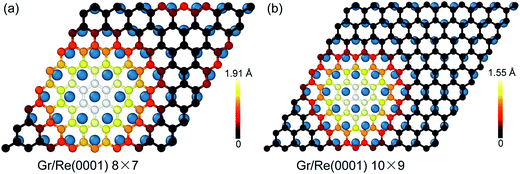
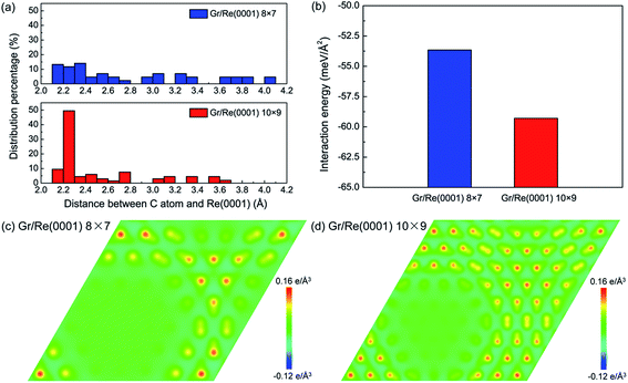
Fig. 1 shows the atomic stacking of graphene and the top layer of the Re(0001) substrate in the 8 × 7 and 10 × 9 models after relaxation. The color on the C atoms reflects the morphology corrugation of graphene. In Fig. 1, the formation of moiré superstructure in both the 8 × 7 and 10 × 9 models can be clearly observed. The periodicities of the moiré superstructures in the 8 × 7 model and in the 10 × 9 model were 1.94 nm and 2.49 nm, respectively. Moreover, the vertical humps were formed in the moiré superstructures and were surrounded by the flat regions, where the C atoms and Re atoms couple with the head to head stacking. Comparing the morphologies of graphene in the 8 × 7 model and in the 10 × 9 model, it can be observed that the corrugation of the hump in the 8 × 7 model is larger than that in the 10 × 9 model, whereas the proportion of the flat region in the 8 × 7 model is obviously smaller than that in the 10 × 9 model. The calculated morphologies of the two moiré superstructures are consistent with the previous experimental observations.17,18 To investigate the stability of the two moiré superstructures, the interaction energy between graphene and Re(0001) substrate and the strain energy in graphene were analyzed.As an indicator to reflect the interaction strength between graphene and the Re(0001) substrate, the distances between C atoms in graphene and the Re(0001) substrate were calculated in the 8 × 7 model and in the 10 × 9 model and are shown in Fig. 2a. In the 10 × 9 model, nearly half of the C atoms in graphene have a smaller distance to the Re(0001) substrate, ranging from 2.2 to 2.3 Å; however, there is a lack of a certain preferential distance between graphene and the Re(0001) substrate in the 8 × 7 model. The interaction energies between graphene and the Re(0001) substrate in the two models were calculated using eqn (1) and indicated that the interaction energy in the 10 × 9 model is indeed lower than that in the 8 × 7 model, as shown in Fig. 2b.
| Einteraction = (EGr/Re − ERe − EGr)/S | (1) |
The charge-transfer distributions between graphene and the Re(0001) substrate could help to reveal the causes of the stronger interfacial interaction intensity in the 10 × 9 model. Fig. 2c and d show the charge-transfer distributions in the (001) planes of the 8 × 7 and 10 × 9 models, and the charge-transfer intensities at the flat region in the two models confirm that their interactions are in the range of covalent interactions. Comparing Fig. 1, Fig. 2c and d, we found more intensive charge-transfer sites in the 10 × 9 model than those in the 8 × 7 model, which is due to the larger proportion of the flat region where the C atoms and Re atoms couple in a head-to-head stacking fashion in the 10 × 9 model.
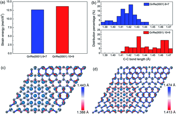
Besides the interfacial interaction energy, as suggested by the observation of giant vertical humps in the graphene/Re(0001) moiré superstructures, the strain energy in graphene should also significantly influence the moiré superstructure stability. Although the hump height of graphene in the 8 × 7 model (1.91 Å) is larger than that in the 10 × 9 model (1.55 Å), as shown in Fig. 1, the graphene strain energy in the 8 × 7 model is a bit smaller, as shown in Fig. 3a; herein, the graphene strain energy was obtained from the following equation:
| Estrain = (EGr − EGr-ideal)/S | (2) |
From Fig. 3a, we found that the strain energies are quite large in the two models. The surprising larger graphene strain energy in the 10 × 9 model relative to that of the 8 × 7 model could be attributed to the relatively larger C–C bond lengths, as illustrated in Fig. 3b. In the 8 × 7 model, the macro-strain in graphene prior to relaxation was 1.75% compressive. After relaxation, the hump formed and elongated the C–C bond lengths in graphene to compensate the previous compressive strain; thus, most of the C–C bond lengths resided around the C–C bond length of graphene (1.42 Å). However, in the 10 × 9 model, the macro-strain in graphene prior to relaxation was 1.06% tensile. After relaxation, most of the C–C bond lengths were further elongated, leading to the larger strain energy in graphene. The detailed C–C bond length distributions are shown in Fig. 3c and d.
Interestingly, we found that with the existence of large strain in the graphene, the C–C bond length distributions spatially varied in the two models. At the flat region, the interaction and stacking between C atoms and Re atoms dominated the bond length distributions. The C–C bonds tended to be stretched to facilitate the stacking of the C atoms and the Re atoms in head-to-head fashion at the fcc and hcp regions of graphene, as defined in previous reports,26 to lower the interaction energy between graphene and the Re(0001) substrate, whereas the C–C bond length evolutions at the hump of graphene in the two models were opposite. Since the interaction between graphene and the Re(0001) substrate was much weaker at the hump, the C–C bonds tended to be close to that in free graphene. Due to the different compulsive strains imposed on the two models, the evolution of C–C bond lengths will be opposite. The rest regions were the bridges between the hump and flat region and the bridges between the hcp and fcc regions, which were both compressed in the two models.
Previous experimental study has interpreted that the discrepancy in the 8 × 7 model and 10 × 9 model could originate from the different methods used to grow graphene in the two experiments.17 Our calculation results indicate that the interaction energy and strain energy in the two models change in the opposite tendency, which might explain the occurrence of both models in the experiments. The direct relationship between the growth conditions and atomic structure still requires further study.
Considering both the interaction energy between graphene and the Re(0001) substrate, and the strain energy in graphene, we found that they are deeply influenced by the interfacial interaction between graphene and the Re(0001) substrate in the two models. The deviation of C–C bond lengths from ideal graphene will introduce a large strain in graphene; however, the strong covalent interaction can greatly reduce the interfacial interaction energy to compensate the increase in the strain energy in graphene. In our calculations, the difference in the interaction energy is more marked than that in the strain energy, and the overall energy of the 10 × 9 model is 4.66 meV Å−2, which is more favored than that of the 8 × 7 model due to its superior geometrical stacking to enlarge the flat region.
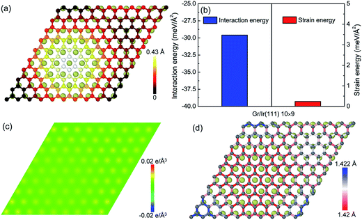
With respect to the weak van der Waals interaction dominating in the graphene/Ir(111) moiré superstructure, the height of the hump in the graphene/Ir(111) moiré superstructure (Fig. 4a) is much lower than that in the graphene/Re(0001) moiré superstructure, as shown in Fig. 1. Moreover, Fig. 4b shows that the interaction energy between graphene and the Ir(111) substrate is much higher than that in the graphene/Re(0001) moiré superstructure (Fig. 2b) due to weak charge transfer between them, as shown in Fig. 4c. However, the strain energy in graphene (Fig. 4b) is extremely lower than that in the graphene/Re(0001) moiré superstructure (Fig. 3a); moreover, with the lack of strong interaction from the substrate, most of the C–C bonds lengths in the graphene/Ir(111) moiré superstructure are close to those in the ideal graphene, as shown in Fig. 4d.
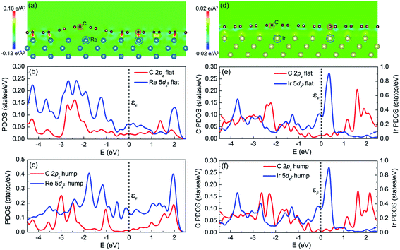
Comparing the graphene/Re(0001) and graphene/Ir(111) moiré superstructures, it is the interfacial interaction (namely the charge transfer) that determines the morphology and stability of graphene on the Re(0001) substrate. The charge transfer distributions in the (1![[1 with combining macron]](https://www.rsc.org/images/entities/char_0031_0304.gif) 0) plane of the graphene/Re(0001) and graphene/Ir(111) moiré superstructures are shown in Fig. 5a and d, respectively. In Fig. 5a, it can be observed that the C atoms tended to interact with the Re atoms in the substrate; however, due to the atomic stacking difference in graphene, only the C atoms at the flat region could intensively interact with the Re(0001) substrate, whereas the region containing hexagonal holes of graphene over the Re atoms corrugates upwards to form the hump. In Fig. 5d, it can be seen that the charge transfer intensities between C atoms and Ir atoms are quite weak at both the hump and the flat region, leading to the flattened morphology close to that of ideal graphene.
0) plane of the graphene/Re(0001) and graphene/Ir(111) moiré superstructures are shown in Fig. 5a and d, respectively. In Fig. 5a, it can be observed that the C atoms tended to interact with the Re atoms in the substrate; however, due to the atomic stacking difference in graphene, only the C atoms at the flat region could intensively interact with the Re(0001) substrate, whereas the region containing hexagonal holes of graphene over the Re atoms corrugates upwards to form the hump. In Fig. 5d, it can be seen that the charge transfer intensities between C atoms and Ir atoms are quite weak at both the hump and the flat region, leading to the flattened morphology close to that of ideal graphene.
Previous studies illustrated that the strong interfacial interactions between graphene and transition metal substrates involve hybridization between C π orbitals and metal d orbitals, especially the hybridization between the C 2pz orbital and the metal dz2 orbital.15,16,24–28 The partial density of states (PDOS) of C atoms (2pz orbital) and Re atoms (5dz2 orbital) at the flat region and hump (labeled in Fig. 5a) helped to understand the charge transfer behavior between C atoms and Re atoms in the flat region. Fig. 5b confirms that the charge transfer behavior is due to the hybridization between the C 2pz orbital and Re 5dz2 orbital, which is reflected in the correspondence of the PDOS curves (peak positions) between the two orbitals, as shown in Fig. 5b, indicating that the covalent interaction dominates at the flat region. However, at the hump, the PDOS curves of the C 2pz orbital and Re 5dz2 orbital are independent, as shown in Fig. 5c, which indicates hybridization did not occur. For the PDOS curves of the C atoms (2pz orbital) and Ir atoms (5dz2 orbital) at both the flat region and the hump in the graphene/Ir(111) moiré superstructure, the hybridization is not observed, as shown in Fig. 5e and f. Thus, the hybridization between the C 2pz orbital and the transition-metal dz2 orbital corresponds to the strong covalent interaction between graphene and the substrate. This strong interfacial interaction further dominates the moiré superstructure of graphene on the substrate. Even for the weak van der Waals interacting Pt(111) substrate, a recent study indicated that at the pinning-points, migration of the electronic charges from the s towards the dz2 orbitals in the Pt atoms increases the orbital directionality, facilitating the hybridization with the pz orbitals of the buckled graphene C atoms.29 By the proper selection and control of the interfacial interaction between graphene and the transition-metal substrate, a variety of moiré superstructures could be synthesized to meet the requirements of the practical applications.
4. Conclusions
In summary, we performed DFT calculations to study the graphene/Re(0001) and graphene/Ir(111) moiré superstructures. By comparing the interaction energy between graphene and the Re(111) substrate, as well as the strain energy of graphene in the two experimentally reported graphene/Re(0001) moiré superstructures, we found that they are deeply influenced by the covalent interfacial interactions. Compared to the strain-driven weak van der Waals interacting graphene/Ir(111) moiré superstructure, we found that interfacial interactions dominate the moiré superstructure of graphene on the covalently interacting Re(0001) substrate. The strong interfacial interaction causes the deviation of C–C bond lengths from those of ideal graphene, but with significant gain in the interfacial interaction energy. The strong covalent interaction between graphene and the Re(0001) substrate is closely related to the hybridization between the C 2pz orbital and Re 5dz2 orbital. This study, therefore, provides a deeper understanding of the moiré superstructures between graphene and the transition-metal substrates.Acknowledgements
The authors would like to acknowledge the support of the National Natural Science Foundation of China (Grant No. 51422504, 51527901, 51375010, 51501012). Simulations were carried out using the “Explorer 100” cluster system of the Tsinghua National Laboratory for Information Science and Technology.References
- W. Yang, G. Chen, Z. Shi, C. C. Liu, L. Zhang, G. Xie, M. Cheng, D. Wang, R. Yang, D. Shi, K. Watanabe, T. Taniguchi, Y. Yao, Y. Zhang and G. Zhang, Nat. Mater., 2013, 12, 792–797 CrossRef CAS PubMed.
- R. Balog, B. Jørgensen, L. Nilsson, M. Andersen, E. Rienks, M. Bianchi, M. Fanetti, E. Lægsgaard, A. Baraldi, S. Lizzit, Z. Sljivancanin, F. Besenbacher, B. Hammer, T. G. Pedersen, P. Hofmann and L. Hornekær, Nat. Mater., 2010, 9, 315–319 CrossRef CAS PubMed.
- C. R. Woods, L. Britnell, A. Eckmann, R. S. Ma, J. C. Lu, H. M. Guo, X. Lin, G. L. Yu, Y. Cao, R. V. Gorbachev, A. V. Kretinin, J. Park, L. A. Ponomarenko, M. I. Katsnelson, Yu. N. Gornostyrev, K. Watanabe, T. Taniguchi, C. Casiraghi, H.-J. Gao, A. K. Geim and K. S. Novoselov, Nat. Phys., 2014, 10, 451–456 CrossRef CAS.
- W. Ouyang, M. Ma, Q. Zheng and M. Urbakh, Nano Lett., 2016, 16(3), 1878–1883 CrossRef CAS PubMed.
- D. Deng, K. S. Novoselov, Q. Fu, N. Zheng, Z. Tian and X. Bao, Nat. Nanotechnol., 2016, 11, 218–230 CrossRef CAS PubMed.
- H. Tetlow, J. Posthuma de Boer, I. J. Ford, D. D. Vvedensky, J. Coraux and L. Kantorovich, Phys. Rep., 2014, 542, 195–295 CrossRef CAS.
- L. Meng, R. Wu, L. Zhang, L. Li, S. Du, Y. Wang and H.-J. Gao, J. Phys.: Condens. Matter, 2012, 24, 314214 CrossRef PubMed.
- A. T. N'Diaye, S. Bleikamp, P. J. Feibelman and T. Michely, Phys. Rev. Lett., 2006, 97, 215501 CrossRef PubMed.
- M. Gao, Y. Pan, L. Huang, H. Hu, L. Z. Zhang, H. M. Guo, S. X. Du and H.-J. Gao, Appl. Phys. Lett., 2011, 98, 033101 CrossRef.
- P. Sutter, J. T. Sadowski and E. Sutter, Phys. Rev. B: Condens. Matter Mater. Phys., 2009, 80, 245411 CrossRef.
- S. Nie, N. C. Bartelt, J. M. Wofford, O. D. Dubon, K. F. McCarty and K. Thürmer, Phys. Rev. B: Condens. Matter Mater. Phys., 2012, 85, 205406 CrossRef.
- Y. Pan, H. Zhang, D. Shi, J. Sun, S. Du, F. Liu and H. Gao, Adv. Mater., 2009, 21, 2777–2780 CrossRef CAS.
- P. W. Sutter, J. I. Flege and E. A. Sutter, Nat. Mater., 2008, 7, 406–411 CrossRef CAS PubMed.
- L. Gao, Y. Liu, T. Ma, R. Shi, Y. Hu and J. Luo, Appl. Phys. Lett., 2016, 108, 261601 CrossRef.
- D. Jiang, M. H. Du and S. Dai, J. Chem. Phys., 2009, 130, 074705 CrossRef PubMed.
- B. Wang, M. L. Bocquet, S. Marchini, S. Günther and J. Wintterlin, Phys. Chem. Chem. Phys., 2008, 10, 3530–3534 RSC.
- C. Tonnoir, A. Kimouche, J. Coraux, L. Magaud, B. Delsol, B. Gilles and C. Chapelier, Phys. Rev. Lett., 2013, 111, 246805 CrossRef CAS PubMed.
- E. Miniussi, M. Pozzo, A. Baraldi, E. Vesselli, R. R. Zhan, G. Comelli, T. O. Menteş, M. A. Niño, A. Locatelli, S. Lizzit and D. Alfè, Phys. Rev. Lett., 2011, 106, 216101 CrossRef CAS PubMed.
- P. Merino, M. Švec, A. L. Pinardi, G. Otero and J. A. Martín-Gago, ACS Nano, 2011, 5(7), 5627–5634 CrossRef CAS PubMed.
- G. Kresse and J. Furthmüller, Phys. Rev. B: Condens. Matter Mater. Phys., 1996, 54, 11169 CrossRef CAS.
- J. Klimes, D. R. Bowler and A. Michelides, J. Phys.: Condens. Matter, 2010, 22, 022201 CrossRef PubMed.
- J. Klimes, D. R. Bowler and A. Michelides, Phys. Rev. B: Condens. Matter Mater. Phys., 2011, 83, 195131 CrossRef.
- T. Björkman, J. Chem. Phys., 2014, 141, 074708 CrossRef PubMed.
- M. Vanin, J. J. Mortensen, A. K. Kelkkanen, J. M. Garcia-Lastra, K. S. Thygesen and K. W. Jacobsen, Phys. Rev. B: Condens. Matter Mater. Phys., 2010, 81, 081408(R) CrossRef.
- P. A. Khomyakov, G. Giovannetti, P. C. Rusu, G. Brocks, J. van den Brink and P. J. Kelly, Phys. Rev. B: Condens. Matter Mater. Phys., 2009, 79, 195425 CrossRef.
- L. Z. Zhang, S. X. Du, J. T. Sun, L. Huang, L. Meng, W. Y. Xu, L. D. Pan, Y. Pan, Y. L. Wang, W. A. Hofer and H.-J. Gao, Adv. Mater. Interfaces, 2014, 1, 1300104 CrossRef.
- A. L. Hsu, R. J. Koch, M. T. Ong, W. Fang, M. Hofmann, K. K. Kim, T. Seyller, M. S. Dresselhaus, E. J. Reed, J. Kong and T. Palacios, ACS Nano, 2014, 8, 7704–7713 CrossRef CAS PubMed.
- A. Dahal and M. Batzill, Nanoscale, 2014, 6, 2548–2562 RSC.
- J. I. Martínez, P. Merino, A. L. Pinardi, O.-I. Gonzalo, M. F. López, J. Méndez and J. A. Martín-Gago, Sci. Rep., 2016, 6, 20354 CrossRef PubMed.
| This journal is © The Royal Society of Chemistry 2017 |

