
 Open Access Article
 This Open Access Article is licensed under a
 Creative Commons Attribution 3.0 Unported Licence
Diffusion of tellurium at nickel grain boundaries: a first-principles study
C. Y. Wanga,
H. Han *a,
D. Wickramaratneb,
W. Zhanga,
H. Wangc,
X. X. Yea,
Y. L. Guoa,
K. Shaoa and
P. Huai*a
*a,
D. Wickramaratneb,
W. Zhanga,
H. Wangc,
X. X. Yea,
Y. L. Guoa,
K. Shaoa and
P. Huai*a
aShanghai Institute of Applied Physics, Chinese Academy of Sciences, Shanghai 201800, P. R. China. E-mail: hanhanfudan@gmail.com; huaiping@sinap.ac.cn
bMaterials Department, University of California, Santa Barbara, CA 93106, USA
cSchool of Physics and Engineering, Henan University of Science and Technology, Luoyang 471003, P. R. China
First published on 24th January 2017
Abstract
The knowledge of the behavior of Te in nickel grain boundaries (GB) is of significant importance for the application of nickel alloys in molten salt reactors. The atomic structures, stabilities, segregation behaviors and diffusion barriers of Te are studied for the bulk, surfaces and four kinds of GBs of nickel. Our first-principles calculations indicate the segregation of Te is most favorable at Σ = 5 (021) GB and the weakest at Σ = 3 (111) GB. The diffusion barriers of Te increase in sequence: Σ = 11 (11![[3 with combining macron]](https://www.rsc.org/images/entities/char_0033_0304.gif) ), Σ = 9 (221), Σ = 3 (111) and Σ = 5 (021). The calculated diffusion barrier of Te on Σ = 11 (11) is 0.35 eV lower than in the bulk, indicating a fast diffusion of Te along this GB. We also consider the effect of strain on the diffusion and find it to be sensitive to the different GB types. When the tensile strain is up to 4%, the diffusion barriers of Te are lowered by 0.51 eV and 0.15 eV for Σ = 5 (021) and Σ = 11 (11), respectively. In contrast, this effect for Σ = 3 (111) is negligible.
), Σ = 9 (221), Σ = 3 (111) and Σ = 5 (021). The calculated diffusion barrier of Te on Σ = 11 (11) is 0.35 eV lower than in the bulk, indicating a fast diffusion of Te along this GB. We also consider the effect of strain on the diffusion and find it to be sensitive to the different GB types. When the tensile strain is up to 4%, the diffusion barriers of Te are lowered by 0.51 eV and 0.15 eV for Σ = 5 (021) and Σ = 11 (11), respectively. In contrast, this effect for Σ = 3 (111) is negligible.
1 Introduction
The growing demands for economical, safe and reliable energy resources have accelerated the development of a new generation of nuclear reactors. The Molten Salt Reactor (MSR), which is one of the most promising new generation reactors, uses molten fluoride salts as coolant and dissolves the actinide fission fuel in the coolant. The strong corrosion of the high temperature liquid fuel brings challenges to the structural materials in MSRs. Historically, Molten Salt Reactor Experiments (MSRE) at Oak Ridge National Laboratory (ORNL, USA) have used Hastelloy N (a nickel-based alloy) as the structural material of choice. However, Hastelloy N exhibits apparent intergranular cracking after exposure to fuel salt. There have been many experimental and theoretical studies1–4 focused on the issue which often claim that the fission-product tellurium (Te) can cause the embrittlement of Hastelloy N. Studies from ORNL also prove that Te is an embrittler for the nickel alloy and it is the inward diffusion of Te along the nickel grain boundaries (GBs) that leads to the embrittlement of the nickel alloy.5 In addition to embrittlement of Ni being caused by Te, nickel alloy embrittlement is also influenced by the external strain and stress given their impact on GB diffusion. Therefore, a deeper knowledge of these properties of Te in GBs is crucial for the understanding of embrittlement of the nickel alloy.GBs are 2-dimentional defects in the crystal structure which are composed by two differently oriented grains. In solids, GBs belong to the most important defects and the properties of GBs are different from that in the crystal interior. In theory there can be a wide range of GB orientations that can occur. For the purposes of this study, we limit our investigations to GB orientations that are most commonly observed in Ni alloys which are computationally tractable, specifically, the symmetrical tilt grain boundary (STGB).6 In the STGBs, Σ = 3 (111), Σ = 5 (021), Σ = 9 (221) and Σ = 11 (11) GBs are all the experimentally confirmed STGB structures in nickel. Σ = 3 (111) GB is the most commonly observed by experiments.7 Σ = 5 (021) is the most frequently used theoretical STGB model which has been utilized in many works.2,8,9 GB diffusion describes the movement of atoms along the GBs under a driving force, i.e., the difference in chemical potentials. It is well known that atoms move in GBs predominantly by simple exchanges with vacancies, i.e., vacancy-mediated diffusion.10 The fact that the impurity atom preferentially diffuses along GBs has already been observed in many other cases, e.g. thorium in tungsten, molybdenum in tungsten, copper in aluminium and copper in nickel.11 However the diffusion properties of Te in Ni grain boundaries remains unexplored. The implications of these properties on the performance of MSR experiments motivate such an investigation.
In this work, the diffusion and segregation behaviors of Te atom along different GB orientations are investigated with the effects of strain included. These results extend our understanding of the physical properties of Te in nickel based alloys and will give a theoretical guide to the experimental work. Then the high corrosion resistant nickel alloys may be manufactured by controlling the concentrations and proportions of different types of GBs. Our results on Te segregation and diffusion variation with respect to the GB orientation emphasize the GB misorientation dependence phenomena existed in crystals.12
2 Computational methods
All calculations in this work were performed with the VASP (Vienna Ab initio Simulation Package) code13 with projector-augmented plane wave (PAW) potentials14 and Perdew–Burke–Ernzerhof (PBE) exchange–correlation functional.15 The wave functions were expanded in a plane-wave basis set with an energy cutoff of 400 eV. Spin polarized calculation was included for Ni contained systems to correctly account for the magnetic properties. Monkhorst–Pack scheme16 was used to sample the Brillouin zone (BZ). Bulk calculations were carried out using a 3 × 3 × 3 supercell of the conventional face-centered cubic (fcc) cells with 108 nickel atoms. Supercells for Σ = 3 (111), Σ = 5 (021), Σ = 9 (221) and Σ = 11 (11) GBs contain 192, 120, 160 and 176 atoms, respectively. And the supercells for the investigated surfaces took the same geometry parameters with their corresponding GBs and contained 96, 48, 80 and 88 atoms, respectively. A 3 × 3 × 3 k-point mesh was employed for the bulk calculation. The k-point meshes of 1 × 3 × 3, 2 × 3 × 4, 1 × 3 × 3, 1 × 3 × 3 were used for Σ = 3 (111), Σ = 5 (021), Σ = 9 (221) and Σ = 11 (11) GBs and their corresponding surfaces, respectively. After the lattice constants being optimized, the subsequent ionic relaxations were allowed within the cell with the volume and shape of the supercell fixed. The vacancy-mediated diffusion barriers were calculated by the climbing-image NEB method.17 All these calculation setups were checked using larger energy cutoff and denser k-mesh; the results of total energy and Hellmann–Feynman forces were convergent within 10−6 eV and 0.01 eV Å−1, respectively.
3 Results and discussions
3.1 Te diffusion in bulk nickel and on nickel surfaces
We first studied the properties of Te atom in the perfect face-centered cubic (fcc) nickel crystal. The optimized lattice parameter of the bulk nickel is 3.515 Å, which is consistent with the existing theoretical (3.518 Å) and experimental value (3.524 Å).3,18 The solution energy is the energy required to place a solute atom at a certain lattice site. It is defined as follows:
 | (1) |
Impurity atoms in a crystal can either occupy the interstitial or substitutional site. The large difference in atomic radii between Te (1.40 A) and Ni (1.24 A) would lead to a large local strain for Te being incorporated interstitially. According to our first-principles calculations, the solution energy of Te atom in the octahedral interstitial site of nickel is 6.29 eV while the value in the tetrahedral interstitial site is even larger, which is 6.93 eV. In contrast, the solution energy of Te in the substitutional configuration is only 0.66 eV. Since the interstitial tellurium in nickel is significantly high in energy it is unlikely to occur when Te is incorporated in Ni. Hence, only the substitutional configuration is considered in our further investigation.
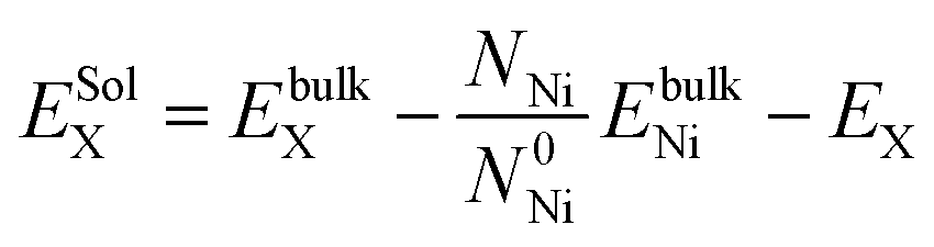
As a large solution species, the diffusion of Te atom in nickel is dominated by the vacancy-mediated mechanism, as shown in Fig. 1(a).19–22 According to our calculation, the vacancy formation energy in nickel is 1.44 eV, which is comparable to that in Cu (1.04 eV) and Ir (1.43 eV) obtained by Nazarov et al.23 The calculated diffusion barrier of a substitutional Te atom to the nearest nickel vacancy is 0.75 eV.
 | ||
| Fig. 1 The diffusion paths of Te atom via vacancy-mediated mechanism for (a) the nickel bulk, (b) the Ni(111), (c) the Ni(021), (d) the Ni(221) and (e) the Ni(11) surfaces. The blue and yellow balls represent Ni and Te atoms, respectively. The blue square represents the vacancy and the blue arrow indicates the Te diffusion path. | ||
Due to the surface effect,24 the properties of Te on different surfaces differ from the bulk properties. The properties of Te on the nickel surfaces were studied by simulating an atomic Te on the top layer of the surfaces. Fig. 1(b–d) depict the investigated diffusion path of Te atom on Ni(111), (021), (221) and (11) surfaces, respectively. The vacancy formation energy (EFVNi), substitutional Te solution energy (ESolTe) and the diffusion barrier (BDif) of Te by the vacancy-mediated mechanism on these nickel surfaces are listed in Table 1. Compared to the EFVNi value in the nickel bulk (1.44 eV), the values for the surfaces decrease obviously, indicating that the nickel surfaces should have larger vacancy concentrations than the bulk. The Ni(021) surface has the lowest value of 0.54 eV, suggesting the vacancies are easily distributed on this surface. Similarly, the solution energy and the diffusion barrier of Te on surfaces are also decreased. The Ni(221) surface has the lowest ESolTe of −2.02 eV. The dramatically lowered ESolTe suggest that Te atom tends to substitute the Ni atom on the surfaces. The Ni(11) surface has the lowest diffusion barrier of Te with the value of only 0.50 eV, suggesting a faster diffusion velocity of Te along this type of GB.
) surfaces
| EFVNi | ESolTe | BDif | |
|---|---|---|---|
| Bulk | 1.44 | 0.66 | 0.75 |
| (111) surface | 1.27 | −1.50 | 0.71 |
| (021) surface | 0.54 | −1.94 | 0.71 |
| (221) surface | 0.63 | −2.02 | 0.89 |
| (11) surface |
0.62 | −1.94 | 0.50 |
3.2 Te diffusion along the GBs
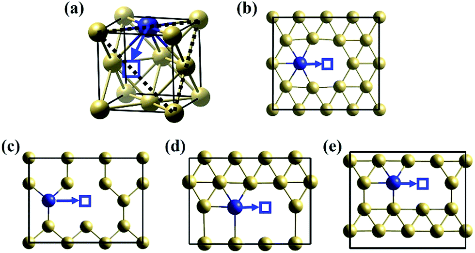
) GB have relatively small grain boundary energies; while the values for Σ = 9 (221) GB and Σ = 5 (021) GB are very high. However, since Σ = 9 (221) GB and Σ = 5 (021) GB can be easily modelled with very few atoms, they are the most widely investigated GBs by theoretical works.3,9,26–31 Shen et al.32 explored the hydrogen segregation to the Σ = 9 (221) STGB in aluminium. Alexandrov et al.30 investigated a wide series of alloying elements diffusing along the Σ = 9 (221) STGB in Ni alloys by ab initio modelling method. Lezzar et al.33 analyzed the segregation driving forces for Ni(Ag) and Ag(Ni) in the Σ = 11 (11) GB using Finnis-Sinclair like potentials. Following these previous studies on the diffusion behavior of many other species at fcc-metal GB, we investigated the Te diffusion at nickel GB by using the same atomic models of Alexandrov et al.30 in this work.As we know, atoms at the GB interface have a different arrangement compared to that in the nickel crystal interior. Fig. 2 shows the structures of Σ = 3 (111), Σ = 5 (021), Σ = 9 (221) and Σ = 11 (11) GBs. Three STGB axes of the investigated four GBs are also depicted in Fig. 2. To obtain the GB structures, the length of the computational box along the direction parallel to the GB interface (axis b and c) is fixed, while along the other direction perpendicular to the plane of the GB interface (axis a) the box size is determined based on the lowest grain boundary energy of GB (γ) with all the internal atoms fully relaxed. The energy is plotted as a function of the strain, as shown in Fig. 3. The optimized box sizes perpendicular to the Σ = 3 (111), Σ = 5 (021), Σ = 9 (221) and Σ = 11 (11) GBs interface plane are 24.43 Å, 16.45 Å, 25.22 Å and 23.70 Å, respectively.
 | ||
| Fig. 2 Side and top views of (a) Σ = 3 (111), (b) Σ = 5 (021), (c) Σ = 9 (221) and (d) Σ = 11 (11) GBs, respectively. The atomic sites are labeled by numbers counted from the GB plane. For clarity, we use the yellow and red balls to represent atoms in adjacent layers (the yellow atoms are in the paper plane, while the red atoms beneath the paper plane). | ||
 | ||
| Fig. 3 The optimization of the lattice parameter a (in Å), which is perpendicular to the GB interface plane. The black, red, blue and green lines indicate the grain boundary energy (γ, in eV Å−2) of the GB for Σ = 3 (111), Σ = 5 (021), Σ = 9 (221) and Σ = 11 (11) GBs, respectively. The supercells are all relaxed with the lattice parameters parallel to the GB interface plane fixed. The lines joining the calculated quantities are drew as eye guidance. | ||
The stability of the GBs is usually assessed by their grain boundary energies34 defined as:
| γ = (Etot − NEcoh)/2A | (2) |
| δV = (Vtot − NΩbulk)/2A | (3) |
Our calculated grain boundary energies and excess volume values are listed in Table 2. The grain boundary energies are ordered in the sequence of Σ = 3 (111) < Σ = 11 (11) < Σ = 5 (021) < Σ = 9 (221). In general the volume expansion of GBs is directly related to the grain boundary energy.36 The excess volumes behave approximately linearly with the grain boundary energies, except for the Σ = 9 (221) GB. The large grain boundary energy of Σ = 9 (221) STGB is originated from the fact that Σ = 9 (221) transitional tilt GB is more stable than Σ = 9 (221) STGB. However, we still employed Σ = 9 (221) STGB just like the GB model of Alexandrov et al.30 in this work because the diffusion study needs tremendous computing workload for Σ = 9 (221) transitional tilt GB. As shown in Table 2, it is obvious that Σ = 3 (111) GB has the lowest excess volume and grain boundary energy. It is reasonable since the interface plane of Σ = 3 (111) GB is the close-packed (111) surface of nickel in which the atomic arrangement is only slightly distorted compared to that in the bulk interior. In contrast, for the other GBs (Σ = 5 (021), Σ = 9 (221) and Σ = 11 (11)), the excess volume of these GBs is relatively larger with respect to Σ = 3 (111) and the atomic arrangement is significantly distorted.
) GBs of nickel
| GBs | Σ = 3 (111) | Σ = 5 (021) | Σ = 9 (221) | Σ = 11 (11) |
|---|---|---|---|---|
| γ | 0.0072 | 0.0818 | 0.1208 | 0.0291 |
| δV | 0.0959 | 0.4039 | 0.2652 | 0.2276 |
| ESeg = EGBb − Ebulkb | (4) |
| Eb = EtotGB,Te − EbulkTe − EtotGB + EbulkNi | (5) |
The binding energy (Eb) and segregation energy (ESeg) of Te at different GB sites are calculated for Σ = 3 (111), Σ = 5 (021) and Σ = 11 (11) GBs, as shown in Fig. 4. However, the related results of Σ = 9 (221) GB cannot be obtained, due to the instability of Σ = 9 (221) STGB after Te doping. This instability is owed to the broken symmetry induced by the impurity doping, which is consistent with the previous studies.32,37 Although a symmetric Σ = 9 (221) GB is a good model to study the diffusion properties of impurities,30 it is not suitable to study the segregation behavior. For Σ = 3 (111), Σ = 5 (021) and Σ = 11 (11) GBs, the most active segregation sites are all at the GB interface plane. The segregation energies increase from the interface plane to the bulk area of the GB for all three GBs. For Σ = 3 (111) and Σ = 11 (11) GBs, the relative large segregation energy (−0.35 eV and −0.54 eV) for Te at the interface layer indicates weak segregation. For Σ = 5 (021) GB, the segregation energy is under −1 eV at the interface. The gradient of its segregation energy is also very large, which indicates a strong tendency for Te segregating to the interface. Therefore, the segregation of Te is most favorable at Σ = 5 (021) GB, while it is the weakest at Σ = 3 (111) GB.
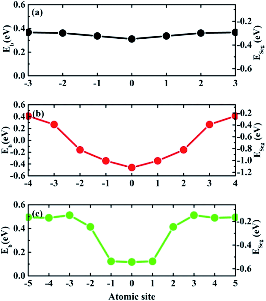 | ||
| Fig. 4 Calculated binding energy (Eb) and segregation energy (ESeg) for one Te atom at each atomic site (the numbers of atomic sites having been labelled in Fig. 2) in the investigated supercells for (a) Σ = 3 (111), (b) Σ = 5 (021) and (c) Σ = 11 (11) GBs. The lines joining the calculated quantities are drew as eye guidance. | ||
) GBs. However, the structural changes of these different GBs have a similar tendency. The bonds perpendicular to the GBs are all elongated greatly. In contrast, the bonds parallel to the GBs are mostly compressed. The expansion induced by the dopant Te across the GB plane could reduce the GB cohesion. Then the Te-doped GBs should fracture more easily than a clean GB, which causes the GB embrittlement.
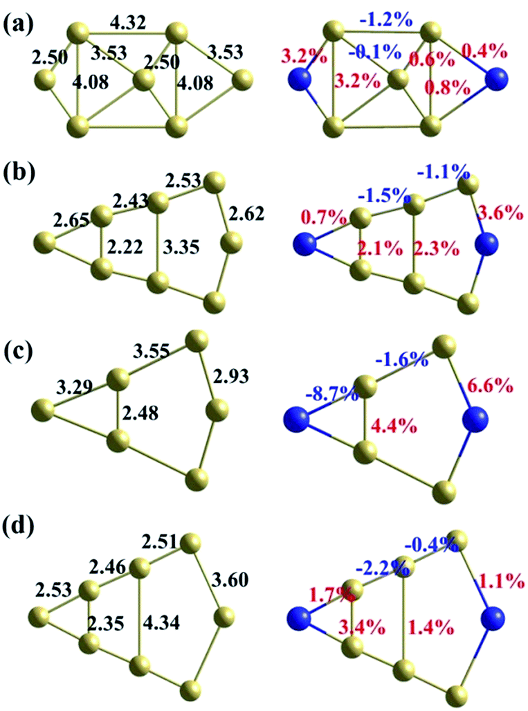 | ||
| Fig. 5 The atomic structures of the clean GB (left) and the Te-doped GB (right) for (a) Σ = 3 (111), (b) Σ = 5 (021), (c) Σ = 9 (221) and (d) Σ = 11 (11) GBs, respectively. The blue and yellow balls represent Te and Ni atom, respectively. On the left panels, the bond lengths (in Å) are shown for the clean GBs. On the right panels, the increased/decreased percentage of the corresponding bond length (in %) are shown for the Te doped GBs. The positive and negative values indicate the bonds are elongated and squashed, respectively. | ||
The embrittlement caused by impurities can also be evaluated by embrittling energy.38 According to the Rice-Wang model, the embrittling energy (ΔEE) can be expressed as the difference between the binding energies of Te atoms at the GB (ΔEGB) and the free surface (ΔEFS):
| ΔEE = ΔEGB − ΔEFS | (6) |
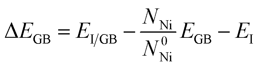 | (7) |
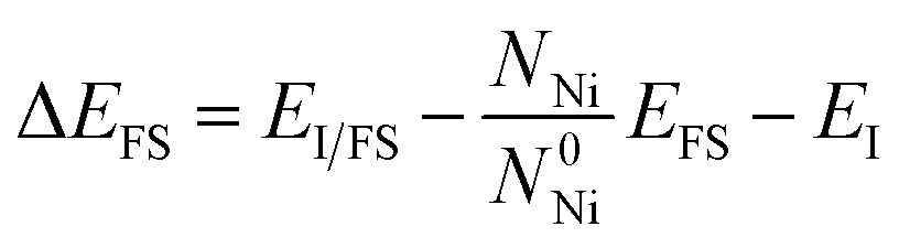 | (8) |
Based on our calculation, the embrittling energies for Σ = 3 (111), Σ = 5 (021), Σ = 9 (221) and Σ = 11 (11) GBs are 2.66 eV, 1.63 eV, 1.74 eV and 2.13 eV, respectively. In terms of the definition of ΔEE, a negative value of ΔEE means enhancement of the GB cohesion, and a positive value corresponds to GB embrittlement. Therefore, the introduced Te atom would cause embrittlement for all these four GBs in nickel alloy.
) GB is the lowest with the value of 0.40 eV. Σ = 9 (221) GB has a relatively small diffusion barrier of 0.66 eV. In contrast, the diffusion barrier of Te along Σ = 3 (111) GB is 0.74 eV, which is close to the value in the bulk. This is consistent with our results that the excess volume for Σ = 3 (111) GB is the lowest (0.10 Å), indicating its atomic structure is close to the bulk. Surprisingly, Σ = 5 (021) GB, which has the highest excess volume, has a very large diffusion barrier of 1.41 eV. According to our above results, the diffusion of Te is most likely to occur along Σ = 11 (11) GB, while the commonly used theoretical model Σ = 5 (021) is not favorable for Te diffusion.
 | ||
| Fig. 6 Top views of Σ = 3 (111), Σ = 5 (021), Σ = 9 (221) and Σ = 11 (11) GBs used to investigate the Te diffusion along the GB via vacancy-mediated mechanism. The Ni, Te atoms and vacancies at GBs are presented by yellow, blue balls and blue squares, respectively. The corresponding diffusion barriers are also indicated. | ||
In the state of tension, the increasing strain will cause the GB interface to fracture into different surfaces. The stress relief by the formation of the corresponding surfaces could change the diffusion barrier of Te atom. Therefore, the above results for Te diffusion at different GBs are compared with the ones on their corresponding surfaces. As listed in Table 1, the calculated diffusion barriers for Ni(111), (021), (221) and (11) surfaces are 0.71 eV, 0.71 eV, 0.89 eV and 0.50 eV, respectively. The diffusion barrier value of 0.71 eV on Ni(111) surface is similar with that at Σ = 3 (111) GB, with a negligible difference of 0.03 eV. The Te atom diffusion barrier value on Ni(021) surface is smaller than the one at Σ = 5 (021) GB by 0.7 eV. In contrast, the Te atom diffusion barrier values on Ni(221) and Ni(11) surfaces are both larger than their counterparts at the GBs by 0.23 eV and 0.10 eV, respectively.
Fig. 7 gives the calculated diffusion barrier of Te atom along four kinds of GBs under different strains. Overall, the results show that the interfacial strain has a similar effect on the Te diffusion behavior at different GBs. The diffusion barriers increase with the GBs under a compressive strain, and decrease under a tensile strain. Therefore, it implies that a tensile strain can increase the diffusivity of Te at nickel GBs. In details, the structures of GBs is also very sensitive to the strain effect. The strain effect for Σ = 3 (111) GB is the smallest and the diffusion barriers' variation is below 0.05 eV for both tension and compression up to 4%. The strain effect for Σ = 9 (221) GB is also relatively small, but the diffusion barrier has a relatively large drop when the tensile strain reach 4% owing to the fact that Σ = 9 (221) transitional tilt GB is more stable than Σ = 9 (221) STGB. The diffusion barrier for Σ = 11 (11) GB is the smallest among the investigated four GBs while the strain effect for this GB is very large. When the tensile strain reaches 4%, the Te diffusion barrier is lowered by 0.15 eV. The lowered barrier is only 0.25 eV, suggesting that Te diffuses fast along the strained Σ = 11 (11) GB. Moreover, it can be found that the Σ = 5 (021) GB exhibits the most remarkable strain effect, and the Te diffusion barrier drops 0.51 eV under a tensile strain of 4%, indicating that Σ = 5 (021) GB is the most sensitive to the tensile strain.
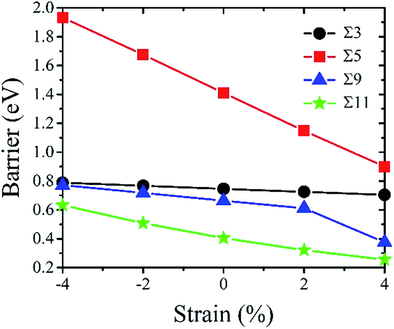 | ||
Fig. 7 Diffusion barriers of Te atom for Σ = 3 (111), Σ = 5 (021), Σ = 9 (221) and Σ = 11 (1![[1 with combining macron]](https://www.rsc.org/images/entities/char_0031_0304.gif) 3) GBs with the GBs changing from the compressed state to the strained state. The lines joining the calculated quantities are drew as eye guidance. 3) GBs with the GBs changing from the compressed state to the strained state. The lines joining the calculated quantities are drew as eye guidance. | ||
In order to clarify the origin of the strong strain effect on the diffusion barrier of Te at Σ = 5 (021) GB, the variation of interlayer distances (Δd) under 4% tensile strain is analyzed. As shown in Fig. 8, for Σ = 3 (111) and Σ = 11 (11) GBs, their interlayer distances increase uniformly under the tensile strain. In contrast, Δd near the interface layer for Σ = 9 (221) GB oscillates strongly. Interestingly, Σ = 5 (021) GB has an obviously different property from the above discussed GBs. As shown in Fig. 8(b), the strain brings about large oscillation of Δd in the two layer region adjacent to the GB interface plane and Δd is up to 13%. When goes beyond the two layers, the oscillation of Δd becomes very small. Therefore, Σ = 5 (021) GB has very large structural variation while being stretched, which explains the strong strain effect on the diffusion barrier of Te. One may argue the Σ = 5 (021) GB has the fewest atoms in our simulations, which may make differences when under a strain. In order to ensure the slab is thick enough to repeat the properties of the Σ = 5 (021) GB, a similar calculation is carried out with the number of layers doubled. As shown in Fig. 8(b), the values obtained by the model with the doubled thickness are consistent with the origin one, indicating the model with 120 atoms is sufficient for Σ = 5 (021) GB.
 | ||
| Fig. 8 The variation of interlayer distances with respect to unstrained cases for (a) Σ = 3 (111), (b) Σ = 5 (021), (c) Σ = 9 (221) and (d) Σ = 11 (11) GBs in terms of numbering of layers under 4% tensile strain. The horizontal line indicates the strain of 4%. The hollow circle in (b) is the data for conventional cell of Σ = 5 (021) GB and the solid circle in (b) is the data for double slab of Σ = 5 (021) GB. The lines joining the calculated quantities are drew as eye guidance. | ||
4 Conclusions
In summary, we have systematically studied the properties of Te at nickel STGBs and demonstrated that they are very sensitive to the GB types.(1) Te is energetically favourable at the substitutional site of nickel for its large atomic volume. Compared to the energy in the nickel bulk, the values of vacancy formation energy, Te substitutional solution energy, and Te diffusion barrier are all decreased obviously on the surfaces, indicating that Te is more easily to diffuse on nickel surfaces by the vacancy-mediated mechanism.
(2) The stability of the GBs is studied by their grain boundary energies. The calculated grain boundary energies are ordered by the following sequences: Σ = 3 (111) < Σ = 11 (11) < Σ = 5 (021) < Σ = 9 (221). And the calculated excess volumes behave approximately linearly to the grain boundary energies, except for the Σ = 9 (221) GB, which originates from the fact that Σ = 9 (221) transitional tilt GB is more stable than Σ = 9 (221) STGB.
(3) The calculated segregation energies indicate that Te has a strong tendency to segregate to the interface layer of the GB. The calculated embrittling energies for nickel GBs are all positive, verifying the embrittling effect of Te atom. The diffusion barrier values are very sensitive to the GB types, and increase in sequence: Σ = 11 (11), Σ = 9 (221), Σ = 3 (111) and Σ = 5 (021) GBs.
(4) The exploration of the applied strain influence on the diffusion barriers is conducted and the diffusion barriers show obvious variations. Our results imply that a tensile strain can greatly increase the diffusivity of Te at nickel GBs, especially for Σ = 5 (021). This is due to the large structural change near the interface layer caused by strain, which explains the strong strain effect on the diffusion barrier of Te at Σ = 5 (021) GB.
Acknowledgements
This work was supported by the Program of International S&T Cooperation (Grant No. 2014DFG60230), National Natural Science Foundation of China (No. 11605273, 91326105, U1404111, 11504089, 21501189, 21676291), the Shanghai Municipal Science and Technology Commission (16ZR1443100), the Strategic Priority Research Program of the Chinese Academy of Sciences (XDA02040104). We also thank the Supercomputing Center of Chinese Academy of Sciences (SCCAS) and the Shanghai Supercomputing Center for computer resources.Notes and references
- W. Liu, H. Han, C. Ren, X. He, Y. Jia, S. Wang, W. Zhang, Z. Li, X. Zhou, Y. Zou, P. Huai and H. Xu, Comput. Mater. Sci., 2014, 88, 22–27 CrossRef CAS.
- M. Yamaguchi, M. Shiga and H. Kaburaki, Science, 2005, 307, 393–397 CrossRef CAS PubMed.
- M. Všianská and M. Šob, Prog. Mater. Sci., 2011, 56, 817–840 CrossRef.
- L. Lu, Y. Jia, X.-X. Ye, M. Luo, F. Song, Y. Huang, X. Zhou, Z. Li and Z. Jiang, Corros. Sci., 2016, 108, 169–172 CrossRef CAS.
- ORNL report No. ORNL/TM-5920, Oak Ridge, Tennessee, US Search PubMed.
- L. Priester, Grain boundaries and crystalline plasticity, John Wiley & Sons, 2011 Search PubMed.
- G. S. Rohrer, E. A. Holm, A. D. Rollett, S. M. Foiles, J. Li and D. L. Olmsted, Acta Mater., 2010, 58, 5063–5069 CrossRef CAS.
- Y. Masatake, S. Motoyuki and K. Hideo, J. Phys.: Condens. Matter, 2004, 16, 3933 CrossRef.
- D. Di Stefano, M. Mrovec and C. Elsässer, Acta Mater., 2015, 98, 306–312 CrossRef CAS.
- I. Kaur, Y. Mishin and W. Gust, Fundamentals of grain and interphase boundary diffusion, John Wiley, 1995 Search PubMed.
- R. S. Barnes, Nature, 1950, 166, 1032–1033 CrossRef CAS.
- G. Gottstein and L. S. Shvindlerman, Grain boundary migration in metals: thermodynamics, kinetics, applications, CRC press, 2009 Search PubMed.
- G. Kresse and J. Furthmüller, Phys. Rev. B: Condens. Matter Mater. Phys., 1996, 54, 11169–11186 CrossRef CAS.
- P. E. Blöchl, Phys. Rev. B: Condens. Matter Mater. Phys., 1994, 50, 17953–17979 CrossRef.
- J. P. Perdew, K. Burke and M. Ernzerhof, Phys. Rev. Lett., 1996, 77, 3865–3868 CrossRef CAS PubMed.
- H. J. Monkhorst and J. D. Pack, Phys. Rev. B: Solid State, 1976, 13, 5188–5192 CrossRef.
- G. Henkelman, B. P. Uberuaga and H. Jónsson, J. Chem. Phys., 2000, 113, 9901–9904 CrossRef CAS.
- A. Dewaele, M. Torrent, P. Loubeyre and M. Mezouar, Phys. Rev. B: Condens. Matter Mater. Phys., 2008, 78, 104102 CrossRef.
- H. Z. Fang, S. L. Shang, Y. Wang, Z. K. Liu, D. Alfonso, D. E. Alman, Y. K. Shin, C. Y. Zou, A. C. T. van Duin, Y. K. Lei and G. F. Wang, J. Appl. Phys., 2014, 115, 043501 CrossRef.
- T. Garnier, V. R. Manga, P. Bellon and D. R. Trinkle, Phys. Rev. B: Condens. Matter Mater. Phys., 2014, 90, 024306 CrossRef.
- T. Jie, H. Han, W. Darshana, L. Wenguan, Z. Mingwen and H. Ping, J. Phys. D: Appl. Phys., 2014, 47, 215301 CrossRef.
- H. Han, D. Wickramaratne, Q. Huang, J. Dai, T. Li, H. Wang, W. Zhang and P. Huai, RSC Adv., 2016, 6, 84262–84268 RSC.
- R. Nazarov, T. Hickel and J. Neugebauer, Phys. Rev. B: Condens. Matter Mater. Phys., 2012, 85, 144118 CrossRef.
- H. Han and J. G. Che, Appl. Phys. Lett., 2013, 103, 163113 CrossRef.
- M. D. Sangid, H. Sehitoglu, H. J. Maier and T. Niendorf, Mater. Sci. Eng., A, 2010, 527, 7115–7125 CrossRef.
- S. Sanyal, U. V. Waghmare, P. R. Subramanian and M. F. X. Gigliotti, Appl. Phys. Lett., 2008, 93, 223113 CrossRef.
- M. Všianská and M. Šob, Phys. Rev. B: Condens. Matter Mater. Phys., 2011, 84, 014418 CrossRef.
- E. L. T. Bentria, I. K. Lefkaier and B. Bentria, Mater. Sci. Eng., A, 2013, 577, 197–201 CrossRef CAS.
- W. Liu, C. Ren, H. Han, J. Tan, Y. Zou, X. Zhou, P. Huai and H. Xu, J. Appl. Phys., 2014, 115, 043706 CrossRef.
- V. Alexandrov, M. L. Sushko, D. K. Schreiber, S. M. Bruemmer and K. M. Rosso, J. Phys. Chem. Lett., 2015, 6, 1618–1623 CrossRef CAS PubMed.
- D. J. Siegel and J. C. Hamilton, Acta Mater., 2005, 53, 87–96 CrossRef CAS.
- X. J. Shen, D. Tanguy and D. Connétable, Philos. Mag., 2014, 94, 2247–2261 CrossRef CAS.
- B. Lezzar, O. Khalfallah, A. Larere, V. Paidar and O. Hardouin Duparc, Acta Mater., 2004, 52, 2809–2818 CrossRef CAS.
- J. J. Bean and K. P. McKenna, Acta Mater., 2016, 110, 246–257 CrossRef CAS.
- E.-M. Steyskal, B. Oberdorfer, W. Sprengel, M. Zehetbauer, R. Pippan and R. Würschum, Phys. Rev. Lett., 2012, 108, 055504 CrossRef PubMed.
- A. Seeger and G. Schottky, Acta Metall., 1959, 7, 495–503 CrossRef CAS.
- L. Wan and S. Wang, Phys. Rev. B: Condens. Matter Mater. Phys., 2010, 82, 214112 CrossRef.
- J. R. Rice and J.-S. Wang, Mater. Sci. Eng., A, 1989, 107, 23–40 CrossRef.
- H. Cheng, F. Han, Y. Jia, Z. Li and X. Zhou, J. Nucl. Mater., 2015, 461, 122–128 CrossRef CAS.
| This journal is © The Royal Society of Chemistry 2017 |