 Open Access Article
Droplet migration on hydrophobic–hydrophilic hybrid surfaces: a lattice Boltzmann study†
Q. Li *,
Y. Yu,
P. Zhou and
H. J. Yan
School of Energy Science and Engineering, Central South University, Changsha 410083, China. E-mail: qingli@csu.edu.cn
First published on 6th March 2017
Abstract
In this paper, the fundamental features and mechanism of droplet migration on hydrophobic–hydrophilic hybrid surfaces are investigated using the lattice Boltzmann method. The hybrid surfaces are textured with pillars, which consist of hydrophobic side walls and hydrophilic tops. First, we study the cases with wettability differences between the sides and the tops of the pillars. It is found that, with an insufficient wetting contrast, the upper contact lines are pinned at the edges of the top surface. With an increase of the contact length between the droplet and the side wall of the pillar, a larger wettability difference is required to induce droplet migration. Meanwhile, it is observed that the migration process is gradually speeded up when the droplet covers more hydrophilic regions of the pillar. Moreover, the influence of the bottom substrate's wettability is investigated. Two types of hybrid surfaces are considered, one of which adopts a wettability difference between the bottom substrate and the sides of pillars. The results show that the droplet migration can be promoted by applying a wetting contrast between the bottom substrate and the sides of the pillars, because the contact length between the droplet and the surface can be reduced with an increase in the hydrophobicity of the bottom substrate.
1. Introduction
Condensation of vapor is prevalent in nature and plays an important role in a variety of engineering applications such as heat exchangers in power and processing industries,1 water harvesting,2 air conditioning3 and water desalination.4 In all of these applications, an efficient condensation process is desired to improve the efficiency of energy conversion. Between the two modes of condensation, the dropwise condensation mode provides an order of magnitude higher heat transfer coefficient than the filmwise condensation mode.5 In the past several decades, significant efforts have been devoted to the study of the underlying mechanisms, methods, and materials for enhancing condensation heat transfer by promoting dropwise condensation. However, achieving sustained dropwise condensation in engineering applications has remained an elusive task.With the rapid development of micro- and nano-fabrication techniques, various engineered surfaces have been designed and fabricated to promote dropwise condensation by making use of micro- and nano-scale features.6–12 Particularly, the advances in surface science have renewed the research interest in tuning surface wettability. In recent years, many studies have been reported on enhancing dropwise condensation through the surfaces with hybrid architectures of hydrophobic/hydrophilic patterns,13–24 which use heterogeneous chemical compositions or employ a combination of heterogeneous chemical compositions and surface texturing to facilitate selective nucleation, growth, and condensate mobilization.25 These hybrid surfaces are similar to the water-capturing surface of a beetle in the Namib desert,26,27 which utilizes its bumpy back with hydrophilic and hydrophobic patches to condense and collect water droplets. For example, Varanasi et al.13 fabricated a textured hybrid surface comprising an array of hydrophobic posts with hydrophilic tops and found that, in contrast to the random nucleation behavior on superhydrophobic surfaces, the hybrid surface promotes nucleation and growth of Cassie-state droplets and therefore exhibits superior droplet shedding properties under condensation. Later, Mishchenko et al.14 also demonstrated the selective nucleation of water droplets on hybrid surfaces.
Inspired by the Namib desert beetle, Hou et al.15 have also proposed a hybrid surface, which consists of micropillar arrays (hydrophilic patches on the top) and surrounding nanograss. They showed that the droplet nucleation density and the droplet growth rate on the hybrid surface are both much higher than that of a superhydrophobic surface without hydrophilic patterns. In addition, He et al.16 designed a micro-/nanoporous superhydrophobic surface modified with hydrophilic polymer and demonstrated that the surface is efficient for controlling microdroplet self-removal. Yao et al.17,18 have investigated the wetting behavior on a hybrid surface with hydrophobic and hydrophilic properties and developed a model based on energy minimization to predict the wettability of a hybrid surface. Moreover, Ölçeroğlu and McCarthy19 designed a hybrid surface consisting of a superhydrophobic nanostructured surface patterned with an array of circular superhydrophilic islands and found that the hybrid surface can effectively delay surface flooding during condensation at increased supersaturations.
Recently, Orejon et al.20 reported experimental observations of droplet migration from the hydrophobic side walls of micropillars to their hydrophilic tops during condensation on a textured hybrid surface. They emphasized that the capability of hybrid surfaces to shift condensate onto the top surfaces of the pillars is critical for subsequent droplet detachment. The directional motion of droplets from hydrophobic strips to hydrophilic strips during condensation on flat surfaces with chemical patterns have also been reported.21,22 Actually, the motion of a droplet on a flat surface due to a wettability gradient has been widely investigated in the literature by both experiments and computer simulations.28–34 However, in comparison with the cases on flat surfaces, droplet migration on a textured surface with wetting contrast is much more complex.
The present work aims at numerically investigating the droplet migration behavior on textured hydrophobic–hydrophilic surfaces and providing an understanding of the mechanism of droplet migration on textured hybrid surfaces. The surfaces are textured with pillars consisting of hydrophobic sides and hydrophilic tops. First, we investigate the influence of the wettability difference between the sides and the tops of pillars. It is found that a larger wettability difference is required to induce droplet migration when the contact length between the droplet and the side wall of the pillar increases. With an insufficient wetting contrast, the upper contact lines are pinned at the edges of the top surface. Later, the influence of the wettability contrast between the bottom substrate and the sides of pillars is investigated. Our results show that the droplet migration can be promoted by applying a wetting contrast between the bottom substrate and the sides of pillars.
The Lattice Boltzmann (LB) method is adopted, which is a mesoscopic numerical approach based on the kinetic theory expressed by the Boltzmann equation.35,36 This method has been applied in a variety of fields with great success,37–39 including droplet moving on smooth surfaces with wettability gradient33,40 and gradient structured surfaces.41 It has advantages in dealing with complex boundaries and incorporating microscopic interactions, both of which are important for simulating interfacial phenomena. In the LB modeling, the interface between different phases can arise, deform and migrate naturally, without resorting to any techniques to track or capture the interface.42,43 The rest of the present paper is organized as follows. In Section 2, we briefly introduce the numerical model. The numerical results and discussions are presented in Section 3. Finally, Section 4 summarizes the present paper.
2. Numerical model
Since the emergence of the LB method, its application in multiphase flows has always been a very important theme of the method.37–39,44 The available multiphase LB models can be generally classified into four categories,39 among which the pseudopotential multiphase LB model45,46 is the simplest one. In this model, the fluid interactions are modeled by an interparticle potential (also called pseudopotential), through which the separation of fluid phases can be achieved automatically. Using a multiple-relaxation-time collision operator,47–49 the LB equation governing the evolution of the density distribution function can be written as follows:
 | (1) |
 is the collision matrix, in which Λ is a diagonal matrix and M is an orthogonal transformation matrix.47 Our simulations are carried out in a rectangular computational domain. Therefore the two-dimensional nine-velocity (D2Q9) lattice model is employed, which has the following discrete velocity vectors:
 | (2) |
 | (3) |
 is the lattice sound speed, and ωα are the weights, which are given by ω0 = 4/9, ω1–4 = 1/9, and ω5–8 = 1/36. By accumulating the density distribution function, the macroscopic density and velocity are obtained as follows:
 | (4) |
 | (5) |
In the pseudopotential multiphase LB model, the interaction force is given by45,46
 | (6) |
 ,51 where peos is a non-ideal equation of state. Here the interaction strength G is to ensure that the whole term inside the square root in ψ(x) is positive and is taken as G = −1. The Peng–Robinson equation of state is adopted in the present work. Yuan and Schaefer51 found that this equation of state has a relatively better performance in the LB modeling in comparison with other equations of state.
In the LB method, the space is discretized in such a way that eαδt is the distance between two neighboring grid points. Then after one time step δt, fα(x,t) arrives at its neighboring grid site along the lattice velocity direction eα. In other words, particles always move on a regular lattice by applying consecutive “collision” and “streaming” processes according to the LB equation. Correspondingly, all the quantities used are dimensionless and lengths are expressed in the unit of the lattice spacing.35
3. Results and discussions
3.1 Simulation details
A simulation box of Lx × Ly = 600 × 300 (lattice units) in two dimensions is adopted in the present work, and a textured hybrid surface is placed at the bottom of the box. The hybrid surface, which is textured with pillars, is illustrated in Fig. 1. The bottom substrate and the side walls of the pillars are hydrophobic, whereas the top surfaces of the pillars are hydrophilic. The center-to-center spacing between two pillars is s = 200 l.u. (l.u. represents lattice units). In the present work, the process of droplet nucleation is not involved, which usually occurs within nanoscale and nanosecond time scale.52 Here we focus on studying the dynamic behavior of droplet migration and small droplets are initially placed on the surface. The initial configuration is equilibrated in a short simulation of 5000 time steps, and then the droplet growth is triggered using a treatment similar to that proposed by Jansen et al.,40 i.e., adding five pixels of liquid density to the liquid phase every 50 time steps, which “mimics” the droplet growth during condensation. The slight increase in density is distributed over all the lattices within the droplet.40 The intrinsic contact angles on the hydrophilic and hydrophobic regions are denoted by θphi and θpho, respectively. The treatment for implementing contact angles in a multiphase LB model can be found in ref. 39. The liquid and vapor densities are chosen as ρL ≈ 6.5 and ρV ≈ 0.38 (l.u.), respectively. The relaxation time τv which determines the kinematic viscosity is set to 1.0. | ||
| Fig. 1 Schematic illustration of the hydrophobic–hydrophilic hybrid surface. The tops of the pillars are hydrophilic, while the sides of the pillars and the bottom substrate are hydrophobic. | ||
3.2 Wettability difference between the sides and the tops of the pillars
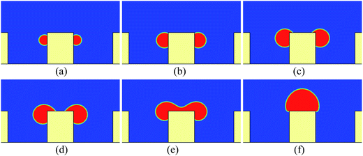
First, we study the cases in which the droplets do not contact the bottom substrate during our simulations. For these cases, the height and the width of the pillars are taken as h = 100 and w = 80 (l.u.), respectively. The periodic boundary condition is applied in the x direction. Initially, a pair of droplets of radius r = 15 (l.u.) is placed on the sides of the central pillar. The vertical distance between the top surface of the pillar and the centers of the droplets is 24 l.u.Some snapshots of the droplet behavior on a textured hybrid surface with θpho = 120° and θphi = 50° are shown in Fig. 2, where ts denotes a thousand time steps. In our simulations, the intrinsic contact angles are implemented without contact angle hysteresis. Therefore it can be seen that in the early stage (Fig. 2a and b) the droplets grow on the sides of the pillar in the constant contact angle (CCA) mode. With the growth of the droplets, the upper three-phase contact lines gradually approach the edges of the top surface and reach the edges at a certain instant. Subsequently, as can be seen from Fig. 2c and d, the upper contact lines cross the edges and move along the top surface, which results from the wettability difference between the sides and the top surface of the pillar. Later, the two droplets coalesce on the top surface of the pillar. Here it should be noted that, since two-dimensional simulations are conducted, our results represent the migration of liquid cylinders in three-dimensional space. In addition, we use the concept of contact lines throughout the present paper, but note that the three-phase contact lines in two dimensions are contact bands with thickness.
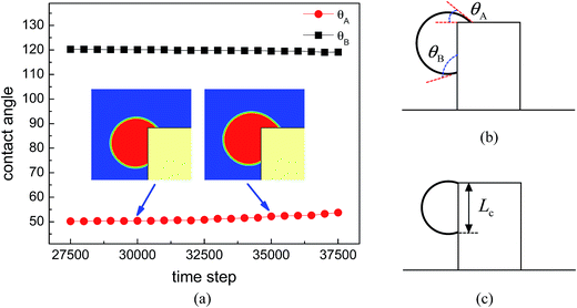
The time evolution of the dynamic contact angles during the migration process on the hybrid surface is presented in Fig. 3, where θA denotes the dynamic contact angle on the top surface of the pillar and θB represents the dynamic contact angle on the side wall of the pillar. The values of θA and θB are evaluated from the simulation results via the circle fitting method (see Fig. S1 in the ESI†). From the figure we can observe an interesting phenomenon that, when the droplet covers a small area of the hydrophilic region (the top surface) of the pillar, the contact angles θA and θB are approximately equal to θphi = 50° and θpho = 120°, respectively; however, with the increase of the covered hydrophilic area, θA gradually increases and θB slightly decreases. When θA ≈ θphi, the motion of the upper contact line along the top surface is mainly dominated by the growth (expansion) of the droplet. Nevertheless, when θA > θphi, there is an unbalanced Young's force towards the right (see Fig. 3 in ref. 42 about the unbalanced Young's force). Meanwhile, the decrease of θB leads to an upward unbalanced Young's force, which also promotes the migration of the droplet. As a result, the migration process will be speeded up (see Movie S1 in the ESI†). Such a phenomenon is consistent with the experimental observation reported in ref. 20: the droplet covers slightly more area of the hydrophilic region until a rapid migration occurs.
If there is no wetting contrast between the sides and the top surface of the pillar, the upper contact lines would be pinned at the edges of the top surface, which can be seen from Fig. 4, where the droplet behavior on a textured surface with uniform wettability is presented for comparison. The pinning phenomenon in Fig. 4 arises from an energy barrier that prevents the transition from the Cassie-Baxter state to the Wenzel state.53,54 Correspondingly, in Fig. 2 the motion of the contact lines from the sides of the pillar to the top surface occurs because the energy barrier has been overcome by applying the wetting contrast. However, with an insufficient wettability difference, the upper contact lines would also be pinned at the edges of the top surface, as can be seen in Fig. 5, in which the droplet behavior on a textured hybrid surface with θpho = 120° and θphi = 60° is displayed.
 | ||
| Fig. 5 Snapshots of droplet behavior on a textured hybrid surface with θpho = 120° and θphi = 60°. (a) t = 18ts, (b) t = 32ts, and (c) t = 60ts. | ||
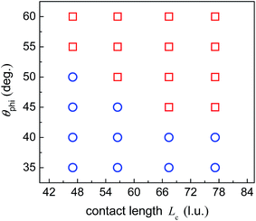
When the upper contact lines reach the edges of the top surface, the contact length between the droplet and the side wall of the pillar is measured, which is defined as Lc (see Fig. 3c). In the above simulations, the contact length Lc is about 47 l.u. By fixing θpho at 120°, a number of cases are considered with varying θphi and Lc so as to quantify the capability of the hybrid surfaces. The contact length Lc is changed by adjusting the position of the initial droplets. The results are depicted in Fig. 6, where the circles denote the cases leading to droplet migration whereas the squares denote the cases in which the upper contact lines are pinned at the edges of the top surface of the pillar. The volume of the droplet before the start of droplet migration is proportional to the contact length Lc since θpho is fixed. From the figure we can see that, when Lc increases, a smaller θphi is required to induce droplet migration. This is mainly attributed to the enhancement of the energy barrier with the increase of the contact length Lc, which prevents the Cassie-Baxter/Wenzel transition. Accordingly, a larger wettability difference is needed to overcome the energy barrier so as to shift the droplets onto the top surface of the pillar.
3.3 Wettability difference between the bottom substrate and the sides of the pillars
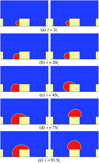
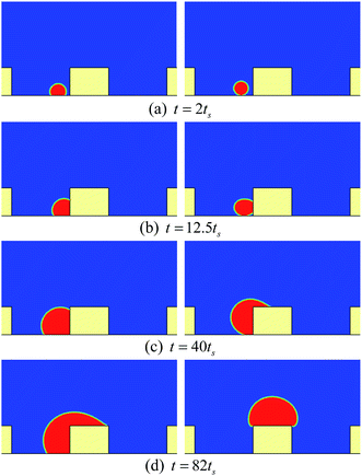
In this section, we turn our attention to the influence of the bottom substrate's wettability. Two types of hybrid surfaces are considered, which are illustrated in Fig. 7. The geometric parameters are the same as those in the previous section except that the height of the pillars is now reduced to 60 l.u. For the A-type surface in Fig. 7, the bottom substrate and the sides of the pillars have the same wettability, while there is a wettability difference between them for the B-type surface (the bottom substrate is more hydrophobic than the sides of the pillars, namely θbom > θpho). Most of the textured hybrid surfaces in the literature are A-type surfaces. The contact angles θphi and θpho are taken as 35° and 120°, respectively. In order to compare the fundamental features of the two types of hybrid surfaces, in our simulations the bottom substrate of the B-type surface is considered to be the same as that of the A-type surface except for the wettability, but note that in practical applications the contact angles of θ > 120° are achieved with surface roughness.Fig. 8 presents a comparison of the droplet behavior on the two types of hybrid surfaces. Initially, a droplet of radius r = 15 (l.u.) is placed on the left side of the central pillar. The droplet growth is triggered after 5000 time steps with the growth rate being reduced by half. The vertical distance between the center of the droplet and the bottom surface is 24 l.u., which means that the droplet should contact the bottom substrate before reaching the top surface of the pillar.
From Fig. 8b we can see that, for the A-type surface, the droplet spreads uniformly on the bottom substrate and the side wall of the pillar after contacting the bottom substrate. However, for the B-type surface, the bottom substrate is less wettable than the sides of the pillars. Consequently, as can be seen from the right panel of Fig. 8b, the contact length between the droplet and the surface is mainly located on the side wall of the pillar. For both surfaces, as time goes by, the droplet gradually covers the left side of the central pillar and approaches the edge of the top surface of the pillar. However, at the instant that the upper contact line reaches the edge of the top surface, the volume of the droplet on the A-type surface is much larger than that of the droplet on the B-type surface (the same case for the contact length between the droplet and the surface), which leads to a large energy barrier for droplet migration on the A-type surface. As a result, the droplet on the A-type surface cannot be shifted onto the top surface of the pillar, while a successful droplet migration can be observed on the B-type surface.
Fig. 9 presents the results of another case in which the initial droplet is placed on the bottom substrate but close to the left side of the central pillar. Such a choice is based on the experimental observation in ref. 20: most of the droplets on the bottom substrate nucleated around the side walls of the pillars. From the left panels of Fig. 9b and c we can also find that the droplet spreads uniformly on the bottom substrate of the A-type surface and the side wall of the central pillar. In contrast, owing to the wettability difference, the droplet on the B-type surface rapidly adheres to the side wall of the pillar after contacting the pillar (see Fig. 9b). Actually, by comparing Fig. 9c with Fig. 8c, we can find that the aforementioned two cases show the same behavior in the late stage although the initial settings are different. According to these results, it is expected that similar phenomena can be observed in the modeling of the cases in which the droplets nucleate at the corners, which is confirmed in our simulations.
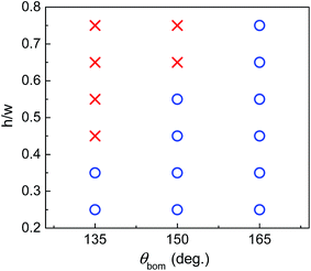
Finally, the influence of the pillar height on the capability of the B-type surface is depicted in Fig. 10, where h/w is the ratio of the pillar height to the pillar width. The pillar width is still set to 80 l.u., while the pillar height varies from 20 to 60 l.u. The initial droplet is placed on the bottom substrate but close to the left side of the central pillar. The circles in Fig. 10 represent the cases in which the droplet can be successfully shifted onto the top surface of the pillar. From the figure we can see that, when θbom is fixed, the increase of the pillar height prevents the migration of the droplet. This is expected since the droplet volume and the contact length before the start of droplet migration increase with the increase of the pillar height, which enhances the energy barrier. Therefore, when the pillar height increases, a larger θbom is required, which helps the droplet reach the edge of the top surface with smaller droplet volume and contact length, as is shown in the right panels of Fig. 8 and 9.
4. Summary
Using the lattice Boltzmann method, we have numerically investigated the droplet migration on hydrophobic–hydrophilic hybrid surfaces, which are textured with pillars consisting of hydrophobic sides and hydrophilic tops. First, we studied the cases in which the droplets reach the edges of the top surface before contacting the bottom substrate. Numerical results showed that the migration of droplets from the sides of a pillar to its top surface arises from the wettability difference between the sides and the top surface of the pillar. Without the wetting contrast or with an insufficient wetting contrast, the upper contact lines were found to be pinned at the edges of the top surface. Meanwhile, it was found that, with the increase of the contact length between the droplet and the side wall of the pillar, a larger wettability difference is required to induce droplet migration. Moreover, we observed that the migration process is gradually speeded up when the droplet covers more hydrophilic region of the pillar.We then investigated the influence of the bottom substrate's wettability. Two types of hybrid surfaces were considered, one of which adopts a wettability difference between the bottom substrate and the sides of the pillars. Through a comparison of the droplet behavior on the two types of hybrid surfaces, it was found that the droplet migration can be promoted by applying a wetting contrast between the bottom substrate and the sides of the pillars, because the droplet volume and the contact length before the start of droplet migration can be reduced with the increase of the hydrophobicity of the bottom substrate. We believe that the present numerical results and findings would be useful for understanding the fundamental features and mechanism of droplet migration on textured hybrid surfaces.
Acknowledgements
This work was supported by the National Natural Science Foundation of China (No. 51506227) and the Foundation for the Author of National Excellent Doctoral Dissertation of China (No. 201439).References
- J. M. Beér, Prog. Energy Combust. Sci., 2007, 33, 107–134 CrossRef.
- A. Lee, M.-W. Moon, H. Lim, W.-D. Kim and H.-Y. Kim, Langmuir, 2012, 28, 10183–10191 CrossRef CAS PubMed.
- X. Chen, Y. Chen, L. Deng, S. Mo and H. Zhang, Appl. Therm. Eng., 2013, 51, 48–54 CrossRef.
- T. Humplik, J. Lee, S. O'hern, B. Fellman, M. Baig, S. Hassan, M. Atieh, F. Rahman, T. Laoui and R. Karnik, Nanotechnology, 2011, 22, 292001 CrossRef CAS PubMed.
- J. G. Collier and J. R. Thome, Convective boiling and condensation, Clarendon Press, 1994 Search PubMed.
- C. K. Law, Prog. Energy Combust. Sci., 1982, 8, 171–201 CrossRef CAS.
- R. D. Narhe and D. A. Beysens, Langmuir, 2007, 23, 6486–6489 CrossRef CAS PubMed.
- C. H. Chen, Q. Cai, C. Tsai, C. L. Chen, G. Xiong, Y. Yu and Z. Ren, Appl. Phys. Lett., 2007, 90, 173108 CrossRef.
- J. B. Boreyko and C. H. Chen, Phys. Rev. Lett., 2009, 103, 184501 CrossRef PubMed.
- X. Chen, J. Wu, R. Ma, M. Hua, N. Koratkar, S. Yao and Z. Wang, Adv. Funct. Mater., 2011, 21, 4617–4623 CrossRef CAS.
- R. D. Narhe and D. A. Beysens, Europhys. Lett., 2006, 75, 98–104 CrossRef CAS.
- C. Dorrer and J. Rühe, Langmuir, 2007, 23, 3820–3824 CrossRef CAS PubMed.
- K. K. Varanasi, M. Hsu, N. Bhate, W. Yang and T. Deng, Appl. Phys. Lett., 2009, 95, 094101 CrossRef.
- L. Mishchenko, M. Khan, J. Aizenberg and B. D. Hatton, Adv. Funct. Mater., 2013, 23, 4577–4584 CrossRef CAS.
- Y. Hou, M. Yu, X. Chen, Z. Wang and S. Yao, ACS Nano, 2015, 9, 71–81 CrossRef CAS PubMed.
- M. He, Q. Zhang, X. Zeng, D. Cui, J. Chen, H. Li, J. Wang and Y. Song, Adv. Mater., 2013, 25, 2291–2295 CrossRef CAS PubMed.
- C. W. Yao, T. P. Garvin, J. L. Alvarado, A. M. Jacobi, B. G. Jones and C. P. Marsh, Appl. Phys. Lett., 2012, 101, 111605 CrossRef.
- C. W. Yao, J. L. Alvarado, C. P. Marsh, B. G. Jones and M. K. Collins, Appl. Surf. Sci., 2014, 290, 59–65 CrossRef CAS.
- E. Ölçeroğlu and M. McCarthy, ACS Appl. Mater. Interfaces, 2016, 8, 5729–5736 Search PubMed.
- D. Orejon, O. Shardt, P. R. Waghmare, N. S. K. Gunda, Y. Takata and S. K. Mitra, RSC Adv., 2016, 6, 36698–36704 RSC.
- A. Ghosh, S. Beaini, B. J. Zhang, R. Ganguly and C. M. Megaridis, Langmuir, 2014, 30, 13103–13115 CrossRef CAS PubMed.
- M. K. Chaudhury, A. Chakrabarti and T. Tibrewal, Extreme Mechanics Letters, 2014, 1, 104–113 CrossRef.
- P. S. Mahapatra, A. Ghosh, R. Ganguly and C. M. Megaridis, Int. J. Heat Mass Transfer, 2016, 92, 877–883 CrossRef.
- J. B. Boreyko, R. R. Hansen, K. R. Murphy, S. Nath, S. T. Retterer and C. P. Collier, Sci. Rep., 2016, 6, 19131 CrossRef CAS PubMed.
- D. Attinger, C. Frankiewicz, A. R. Betz, T. M. Schutzius, R. Ganguly, A. Das, C.-J. Kim and C. M. Megaridis, MRS Energy & Sustainability, 2014, 1, E4 Search PubMed.
- A. R. Parker and C. R. Lawrence, Nature, 2001, 414, 33–34 CrossRef CAS PubMed.
- L. Zhai, M. C. Berg, F. Ç. Cebeci, Y. Kim, J. M. Milwid, M. F. Rubner and R. E. Cohen, Nano Lett., 2006, 6, 1213–1217 CrossRef CAS PubMed.
- R. S. Subramanian, N. Moumen and J. B. McLaughlin, Langmuir, 2005, 21, 11844–11849 CrossRef CAS PubMed.
- N. Moumen, R. S. Subramanian and J. B. McLaughlin, Langmuir, 2006, 22, 2682–2690 CrossRef CAS PubMed.
- J. D. Halverson, C. Maldarelli, A. Couzis and J. Koplik, J. Chem. Phys., 2008, 129, 164708 CrossRef PubMed.
- X. Zhu, H. Wang, Q. Liao, Y. D. Ding and Y. B. Gu, Exp. Therm. Fluid Sci., 2009, 33, 947–954 CrossRef CAS.
- X. P. Xu and T. Z. Qian, Phys. Rev. E: Stat., Nonlinear, Soft Matter Phys., 2012, 85, 051601 CrossRef PubMed.
- J. J. Huang, H. B. Huang and X. Z. Wang, Phys. Fluids, 2014, 26, 062101 CrossRef.
- M. Chakraborty, A. Chowdhury, R. Bhusan and S. DasGupta, Langmuir, 2015, 31, 11260–11268 CrossRef CAS PubMed.
- S. Succi, The Lattice Boltzmann Equation for Fluid Dynamics and Beyond, Oxford University Press, Oxford, 2001 Search PubMed.
- A. A. Mohamad, Lattice Boltzmann Method: Fundamentals and Engineering Applications with Computer Codes, Springer Science & Business Media, 2011 Search PubMed.
- S. Chen and G. D. Doolen, Annu. Rev. Fluid Mech., 1998, 30, 329–364 CrossRef.
- C. K. Aidun and J. R. Clausen, Annu. Rev. Fluid Mech., 2010, 42, 439–472 CrossRef.
- Q. Li, K. H. Luo, Q. J. Kang, Y. L. He, Q. Chen and Q. Liu, Prog. Energy Combust. Sci., 2016, 52, 62–105 CrossRef.
- H. P. Jansen, K. Sotthewes, J. van Swigchem, H. J. W. Zandvliet and E. S. Kooij, Phys. Rev. E: Stat., Nonlinear, Soft Matter Phys., 2013, 88, 013008 CrossRef PubMed.
- G. H. Tang, H. H. Xia and Y. Shi, J. Appl. Phys., 2015, 117, 244902 CrossRef.
- Q. Li, P. Zhou and H. J. Yan, Langmuir, 2016, 32, 9389–9396 CrossRef CAS PubMed.
- Q. Zhang, D. Sun, Y. Zhang and M. Zhu, Langmuir, 2014, 30, 12559–12569 CrossRef CAS PubMed.
- H. Huang, M. Sukop and X. Lu, Multiphase lattice Boltzmann methods: Theory and application, John Wiley & Sons, 2015 Search PubMed.
- X. Shan and H. Chen, Phys. Rev. E: Stat. Phys., Plasmas, Fluids, Relat. Interdiscip. Top., 1993, 47, 1815–1820 CrossRef.
- X. Shan and H. Chen, Phys. Rev. E: Stat. Phys., Plasmas, Fluids, Relat. Interdiscip. Top., 1994, 49, 2941–2948 CrossRef CAS.
- P. Lallemand and L.-S. Luo, Phys. Rev. E: Stat. Phys., Plasmas, Fluids, Relat. Interdiscip. Top., 2000, 61, 6546–6562 CrossRef CAS.
- Q. Li, K. H. Luo and X. J. Li, Phys. Rev. E: Stat., Nonlinear, Soft Matter Phys., 2013, 87, 053301 CrossRef CAS PubMed.
- L.-S. Luo, W. Liao, X. Chen, Y. Peng and W. Zhang, Phys. Rev. E: Stat., Nonlinear, Soft Matter Phys., 2011, 83, 056710 CrossRef PubMed.
- Q. Li, Q. J. Kang, M. M. Francois, Y. L. He and K. H. Luo, Int. J. Heat Mass Transfer, 2015, 85, 787–796 CrossRef.
- P. Yuan and L. Schaefer, Phys. Fluids, 2006, 18, 042101 CrossRef.
- W. Xu, Z. Lan, B. L. Peng, R. F. Wen and X. H. Ma, RSC Adv., 2016, 6, 7923–7932 RSC.
- D. Murakami, H. Jinnai and A. Takahara, Langmuir, 2014, 30, 2061–2067 CrossRef CAS PubMed.
- W. Ren, Langmuir, 2014, 30, 2879–2885 CrossRef CAS PubMed.
Footnote |
| † Electronic supplementary information (ESI) available. See DOI: 10.1039/c6ra28665h |
| This journal is © The Royal Society of Chemistry 2017 |

