 Open Access Article
Wasp-waisted behavior in magnetic hysteresis curves of CoFe2O4 nanopowder at a low temperature: experimental evidence and theoretical approach
Tibério Magno de Lima Alvesab,
Bruno Ferreira Amorimb,
Marco Antonio Morales Torresb,
Claudionor Gomes Bezerra *b,
Suzana Nóbrega de Medeirosb,
Pedro Lana Gasteloisc,
Luis Eugenio Fernandez Outoncd and
Waldemar Augusto de Almeida Macedoc
aInstituto Federal de Educação Ciência e Tecnologia do Rio Grande do Norte, 59015-000 Natal, RN, Brazil
bDepartamento de Física Teórica e Experimental, Universidade Federal do Rio Grande do Norte, 59078-900 Natal, RN, Brazil. E-mail: cbezerra@fisica.ufrn.br
cLaboratório de Física Aplicada, Centro de Desenvolvimento da Tecnologia Nuclear, CDTN, 31970-201 Belo Horizonte, MG, Brazil
dDepartamento de Física, Universidade Federal de Minas Gerais, 31270-901 Belo Horizonte, MG, Brazil
First published on 20th April 2017
Abstract
We theoretically and experimentally investigated wasp-waisted magnetic hysteresis curves at a low temperature for CoFe2O4 nanopowders. Our theoretical approach proposes a physical mechanism that leads to wasp-waisted behavior for a single magnetic phase with the same anisotropic field, contrary to that of typical multi-phase magnetic systems. Our simulations show that a combination of effects, namely easy-plane anisotropy configuration and dipolar interactions, results in a double peak in the magnetic susceptibility curve of a granular magnetic system. As experimental evidence of such an effect, we present a CoFe2O4 nanopowder and its structural and magnetic characterizations, which support a single magnetic phase. In addition, the evidence does not corroborate many explanations reported in the literature for wasp-waisted magnetic behavior. Our results provide evidence for a tetragonal crystalline phase of CoFe2O4 due to magneto-elastic coupling, recently reported in the literature.
1 Introduction
Recently, some nanometric granular magnetic systems have displayed “wasp-waisted”-like magnetic hysteresis curves at low temperatures, especially CoFe2O4 nanoparticles, and such phenomena have been attributed to many mechanisms. Direct insight could lead to an interpretation of what occurs in the magnetic multi-phase systems of rocks,1 where the material possesses a hard magnetic phase with a high value of the coercive field and a soft magnetic phase with a lower coercive field value. Some authors attribute this phenomenon to a superposition of superparamagnetic and single-domain phases, as presented in the work of Roberts et al.,2 because the superparamagnetic phase has null coercivity and the hard blocked magnetic single-domain phase does not. Abrupt changes in the magnetization curve around a zero magnetic field could be expected in this case. However, a mixture of a single-domain phase (high coercivity) and a multi-domain phase (low coercivity) could also reproduce the wasp-waisted magnetic hysteresis curves.2For Co0.6Sn0.4Fe2O4 nanoparticles with an average grain size of approximately 20 nm,3 another explanation is based on the superexchange interaction configuration between metallic cations in the spinel structure being changed by the occupation number of Co2+ ions in the A-sites (tetrahedral), which tends to remove Fe3+ from the A-sites to B-sites (octahedral). This diminishes the effect of the superexchange coupling A–B interaction as compared to the A–A and B–B interactions. This leads to a magnetic structure that is changed from the well-established antiferromagnetic phase to competing ferromagnetic and antiferromagnetic phases. In the work of Chithra et al.,4 cobalt ferrite nanoparticles were also produced, and the wasp-waisted behavior was attributed to two groups of particles with different anisotropies leading to a double peak in the susceptibility curves and exhibiting an exchange-spring-like behavior. In the work of Song and Zhang,5 bimagnetic spinel cobalt ferrite and manganese ferrite with core–shell structures also reproduced the wasp-waisted hysteresis curves. However, concerning cobalt ferrite nanoparticles, Fu et al.6 showed that the CoFe2O4 nanoparticles exhibit the same behavior in a nanotube geometry, unlike that which occurs in nanorod7 and nanowire8 geometries. Xu et al.9 showed that jumps around H = 0 in the magnetic hysteresis cycles of CoFe2O4 nanoparticles can be attributed to spin re-orientation at low temperatures due to canted spins on the surfaces of the nanoparticles. If the surface/volume ratio of the nanoparticles increases, the surface effects tend to dominate the magnetic properties.
Coated L10 tetragonal-phase FePt nanoparticles, presented in the work of Lee et al.,10 displayed “constricted” hysteresis curves and this effect was attributed to dipolar interactions between nanoparticles, which cause abrupt changes in magnetization around zero applied magnetic field in the hysteresis cycle. In this case, when the thickness of the encapsulation layer is increased, the effect of constriction in the hysteresis curves is suppressed considerably, demonstrating that wasp-waisted hysteresis curves could also be attributed to dipolar interactions between single-domain nanoparticles.
In this work, we propose a theoretical approach that presents another physical mechanism leading to wasp-waisted-like hysteresis curves. Our model is based on the coherent rotation of single-domain nanoparticles, considering a uniaxial easy-plane anisotropy configuration and dipolar interactions without the effects of temperature. Interactions are a topic of great interest in the literature concerning magnetic granular systems, especially concerning how their superposition with anisotropic fields can change the magnetic properties. Many efforts have been made to investigate dipolar fields in granular systems that have cubic11 and easy-axis12–16 anisotropy configurations; however, studies concerning easy-plane configurations are scarce.
We also present experimental evidence from ball-milled CoFe2O4 nanopowders using various characterization methods to ensure that the proposed theoretical mechanism is likely to explain the static magnetic properties of our sample.
2 Experiment
Synthesis of the stoichiometric CoFe2O4 nanoparticles was performed in a planetary ball-mill (Fritsch Pulverisette 7 – Premium line), with a vial and balls made of hardened steel, in an air atmosphere, followed by thermal annealing. The process involved milling stoichiometric amounts of γ-Fe2O4 and Co3O4 powders, used as precursors, which were both purchased from Sigma-Aldrich. The balls and powder were placed in a vial and milled for 10 h, intercalating 10 min of rest for every 1 h of milling time to reduce heating. The parameters used in the milling were a ball-to-powder mass ratio of 20![[thin space (1/6-em)]](https://www.rsc.org/images/entities/char_2009.gif) :
:![[thin space (1/6-em)]](https://www.rsc.org/images/entities/char_2009.gif) 1 and an angular velocity of 300 rpm. After milling, the powders were annealed at 900 °C for 2 h.
1 and an angular velocity of 300 rpm. After milling, the powders were annealed at 900 °C for 2 h.
Phase characterization of the sample was performed via X-ray diffraction (XRD) using a Rigaku MiniFlex II diffractometer, with CuKα radiation of λ = 1.541 Å. The XRD data were collected at room temperature, with a 2θ range between 20° and 70°, scan rate of 5° min−1 and 0.02° step. The XRD pattern was identified using the JCPDS database and refined using the Rietveld method with the MAUD program, which was provided with the structural parameters. The sample density was estimated using the relationship Dx = 8 wt/Na3,17 where wt is the molecular weight of the sample, N is Avogadro’s number, and a is the lattice parameter of the unit cell.
The morphologies and grain size distributions of the nanopowders were analyzed using a transmission electron microscope (TEM) (Jeol, JEM-2100) equipped with an energy dispersive X-ray spectroscope (EDS).
Mössbauer spectra (MS) were recorded in transmission mode at a low temperature (12 K) and constant acceleration mode using a conventional commercial spectrometer (SEE Co), with gamma rays provided by a 57Co(Rh) source. The MS were analyzed using a non-linear least-squares routine, with a Lorentzian line shape. The isomer shift values are related to α-Fe at 300 K.
X-ray photoelectron spectroscopy analysis (XPS-Specs, Phoibos-150 electron analyzer), using monochromatized Al K-α radiation (1486.6 eV) at a power of 350 W, was carried out to characterize the valence states of iron and cobalt in the sample. High-resolution spectra were acquired using 0.1 eV step energy and 20 eV passage energy. The spectra were fitted using Casa XPS software, resulting in RES STD <1.
The magnetic hysteresis loop was recorded in a commercial VSM – PPMS DynaCool from Quantum Design. The measurements were performed with magnetic fields between ±140 kOe at 5 K.
3 Model
Our modeling approach consists of building an L edge simulation square box, which contains a set of randomly positioned N single-domain nanoparticles with particle size determined from a log-normal size distribution, with a pre-defined concentration c (see Fig. 1(a)), and obeying a non-overlapping criterion. We choose a coordinate system that coincides with the edges of the simulation box. The i-th nanoparticle is characterized by the position![[r with combining right harpoon above (vector)]](https://www.rsc.org/images/entities/i_char_0072_20d1.gif) i (see Fig. 1(b)), and crystallographic orientation defined by the unitary vector ûi, with polar angles θui and ϕui (see Fig. 1(c)), as well as by its magnetic moment
i (see Fig. 1(b)), and crystallographic orientation defined by the unitary vector ûi, with polar angles θui and ϕui (see Fig. 1(c)), as well as by its magnetic moment ![[small mu, Greek, vector]](https://www.rsc.org/images/entities/i_char_e0e9.gif) i = MsVi
i = MsVi![[m with combining circumflex]](https://www.rsc.org/images/entities/i_char_006d_0302.gif) i. Here, Ms is the saturation magnetization (considered the same for all particles), Vi is the volume of the nanoparticle, and
i. Here, Ms is the saturation magnetization (considered the same for all particles), Vi is the volume of the nanoparticle, and ![[m with combining circumflex]](https://www.rsc.org/images/entities/i_char_006d_0302.gif) i is a dimensionless unitary vector, with polar angles θi and ϕi.
i is a dimensionless unitary vector, with polar angles θi and ϕi.
Let us describe the magnetic energy terms that compose the free magnetic energy. In a magnetic field ![[H with combining right harpoon above (vector)]](https://www.rsc.org/images/entities/i_char_0048_20d1.gif) , the i-th single-domain nanoparticle presents a Zeeman energy given by
, the i-th single-domain nanoparticle presents a Zeeman energy given by
EZi = −![[small mu, Greek, vector]](https://www.rsc.org/images/entities/i_char_e0e9.gif) i· i·![[H with combining right harpoon above (vector)]](https://www.rsc.org/images/entities/i_char_0048_20d1.gif) . .
| (1) |
Since our sample presents an average grain size of approximately 60 nm, we expect that the effects of the surface anisotropy will be suppressed by the magneto-crystalline anisotropy of the core material. Therefore, the magneto-crystalline anisotropy is the dominant anisotropy in the sample. We consider a magneto-crystalline anisotropy following uniaxial symmetry, i.e.,18
| Eai = [K1αi2 + K2αi4]Vi. | (2) |
Here, K1 and K2 are the uniaxial magneto-crystalline anisotropy constants. In addition, αi is the direction cosines of the magnetization related to the uniaxial crystallographic axes of the i-th nanoparticle. This quantity has to be transformed through inverse rotations θui and ϕui (see Fig. 1(c)) in order to formulate the anisotropic energy in terms of the coordinate system of the simulation box.
Regarding the interaction between particles, dipolar interactions are included in our model. If ![[r with combining right harpoon above (vector)]](https://www.rsc.org/images/entities/i_char_0072_20d1.gif) i and
i and ![[r with combining right harpoon above (vector)]](https://www.rsc.org/images/entities/i_char_0072_20d1.gif) j are the positions of the i-th and j-th particles, respectively, the dipolar field Hdipij due to the j-th particle acting on the i-th particle is given by
j are the positions of the i-th and j-th particles, respectively, the dipolar field Hdipij due to the j-th particle acting on the i-th particle is given by
 | (3) |
Here, rij = |![[r with combining right harpoon above (vector)]](https://www.rsc.org/images/entities/i_char_0072_20d1.gif) i −
i − ![[r with combining right harpoon above (vector)]](https://www.rsc.org/images/entities/i_char_0072_20d1.gif) j| is the distance between the i-th and j-th particles. Therefore, the superposition of the dipolar fields acting on the i-th particle can be written as
j| is the distance between the i-th and j-th particles. Therefore, the superposition of the dipolar fields acting on the i-th particle can be written as
 | (4) |
![[H with combining right harpoon above (vector)]](https://www.rsc.org/images/entities/i_char_0048_20d1.gif) effi = effi = ![[H with combining right harpoon above (vector)]](https://www.rsc.org/images/entities/i_char_0048_20d1.gif) + + ![[H with combining right harpoon above (vector)]](https://www.rsc.org/images/entities/i_char_0048_20d1.gif) dipi. dipi.
| (5) |
Considering the Zeeman, dipolar, and magneto-crystalline anisotropic energies, one can write the free magnetic energy of the i-th particle as
Ei = −![[H with combining right harpoon above (vector)]](https://www.rsc.org/images/entities/i_char_0048_20d1.gif) effi· effi·![[m with combining circumflex]](https://www.rsc.org/images/entities/i_char_006d_0302.gif) iMsVi + [K1αi2 + K2αi4]Vi. iMsVi + [K1αi2 + K2αi4]Vi.
| (6) |
Since we are interested in describing the static magnetic properties at low temperatures, our approach consists of locally minimizing the free magnetic energy of each individual particle using the steepest descend method to find the equilibrium orientation state and then calculate the magnetization in a completely blocked state of temperature (temperature effects are not considered). In this regard, it is useful to reduce the number of parameters by dividing eqn (6) by 2|K1|Vi, which leads to the reduced free magnetic energy
 | (7) |
Here, ![[h with combining right harpoon above (vector)]](https://www.rsc.org/images/entities/i_char_0068_20d1.gif) effi =
effi = ![[H with combining right harpoon above (vector)]](https://www.rsc.org/images/entities/i_char_0048_20d1.gif) effi/Hk1 is the reduced effective magnetic field, Hk1 = 2|K1|/Ms, and a = K2/|K1|.
effi/Hk1 is the reduced effective magnetic field, Hk1 = 2|K1|/Ms, and a = K2/|K1|.
To implement our simulation, we consider a log-normal size distribution of particles
 | (8) |
Here, y = d/dm, where d is the particle diameter, dm is the average particle diameter, and σ is the standard deviation of the distribution. Because of the finite size of the simulation box, we applied a cut-off range for the dipolar field,19–21 which is defined by a critical radius, rc = 5dm. This means that, for a given particle, only the field produced by the surrounding particles within the range of rc is considered. We should remark that, for different concentrations, slightly different values of rc were observed. We have verified that a critical radius rc larger than 5dm does not substantially change the results.
We divide the edges of our box simulation by L, defining ![[r with combining right harpoon above (vector)]](https://www.rsc.org/images/entities/i_char_0072_20d1.gif) ′ =
′ = ![[r with combining right harpoon above (vector)]](https://www.rsc.org/images/entities/i_char_0072_20d1.gif) /L. The concentration is given by
/L. The concentration is given by  , which can be rewritten as c = N〈V〉L3. Here, N is the number of particles and 〈V〉 is the average volume calculated from f(y). Once 〈V〉 = πdm3〈y3〉/6, the concentration can be expressed as
 | (9) |
 | (10) |
 | (11) |
The static magnetic properties are obtained by calculating the average component of the magnetization along the reduced magnetic field h = H/Hk1, i.e.,
 | (12) |
![[m with combining circumflex]](https://www.rsc.org/images/entities/i_char_006d_0302.gif) i·ẑ is the reduced component of the magnetization of the i-th particle as a function of the reduced magnetic field h. To compare our theoretical results with experimental data, we calculate the reduced coercive field hc and the reduced remanant magnetization 〈m(0)〉 = mr, which are related to the experimental coercive field Hc, remanant magnetization Mr and saturation magnetization Ms by hc = Hc/Hk1 and 〈m(0)〉 = mr = Mr/Ms.
i·ẑ is the reduced component of the magnetization of the i-th particle as a function of the reduced magnetic field h. To compare our theoretical results with experimental data, we calculate the reduced coercive field hc and the reduced remanant magnetization 〈m(0)〉 = mr, which are related to the experimental coercive field Hc, remanant magnetization Mr and saturation magnetization Ms by hc = Hc/Hk1 and 〈m(0)〉 = mr = Mr/Ms.
4 Numerical method
We can summarize our theoretical procedure as follows:(i) We set the ratio a, as well as the concentration c and standard deviation σ. Then, we calculate d′m and 〈y3〉 for N particles.
(ii) The packing process involves setting random positions (![[r with combining right harpoon above (vector)]](https://www.rsc.org/images/entities/i_char_0072_20d1.gif) ′1,
′1, ![[r with combining right harpoon above (vector)]](https://www.rsc.org/images/entities/i_char_0072_20d1.gif) ′2) and sizes (y1, y2) in the reduced simulation box for the first and second particles. We perform a test to determine if this pair of particles obeys the non-overlapping criterion r′12 > d′m(y1 + y2)/2. Then, we increase the number of particles one by one until N particles are created that obey the non-overlapping criterion, thus completing the packing process.
′2) and sizes (y1, y2) in the reduced simulation box for the first and second particles. We perform a test to determine if this pair of particles obeys the non-overlapping criterion r′12 > d′m(y1 + y2)/2. Then, we increase the number of particles one by one until N particles are created that obey the non-overlapping criterion, thus completing the packing process.
(iii) A set of coordinates (θu, ϕu, θ, ϕ) is associated with each particle. Here, θu and ϕu are random in the intervals 0 ≤ θu ≤ π and 0 ≤ ϕu ≤ 2π. We assume saturation in the −ẑ direction as the initial configuration, which means taking θ = π and ϕ = 0 for all particles.
(iv) The reduced dipolar field is calculated for all of the particles, following the cut-off criterion previously defined by rc = 5dm, and the reduced applied magnetic field is set as ![[h with combining right harpoon above (vector)]](https://www.rsc.org/images/entities/i_char_0068_20d1.gif) = −hsatẑ, where hsat is the saturation reduced magnetic field.
= −hsatẑ, where hsat is the saturation reduced magnetic field.
(v) The effective magnetic field ![[h with combining right harpoon above (vector)]](https://www.rsc.org/images/entities/i_char_0068_20d1.gif) eff =
eff = ![[h with combining right harpoon above (vector)]](https://www.rsc.org/images/entities/i_char_0068_20d1.gif) +
+ ![[h with combining right harpoon above (vector)]](https://www.rsc.org/images/entities/i_char_0068_20d1.gif) dip is calculated, and a local minimization process is employed (steepest descent) to obtain the equilibrium positions (θ and ϕ) of all particles. Then, 〈m(h)〉 is numerically calculated.
dip is calculated, and a local minimization process is employed (steepest descent) to obtain the equilibrium positions (θ and ϕ) of all particles. Then, 〈m(h)〉 is numerically calculated.
(vi) The new reduced dipolar field is recalculated for all particles, and the reduced applied magnetic field is increased by a step of Δh. New equilibrium orientations as well as the new value of 〈m(h)〉 are calculated. This process continues until ![[h with combining right harpoon above (vector)]](https://www.rsc.org/images/entities/i_char_0068_20d1.gif) = hsatẑ is reached and returns to
= hsatẑ is reached and returns to ![[h with combining right harpoon above (vector)]](https://www.rsc.org/images/entities/i_char_0068_20d1.gif) = −hsatẑ, completing the reduced hysteresis loop.
= −hsatẑ, completing the reduced hysteresis loop.
We should remark that, to avoid finite size and boundary effects, we evaluate 〈m(h)〉 considering particles inside a simulation box with edges equal to 0.9L, centered within the original simulation box.
5 Results and discussion
5.1 Structural and chemical analysis
The X-ray diffraction patterns, along with the fitting data for the powders used as precursors and the CoFe2O4 sample, are shown in Fig. 2. The Rietveld refinement confirms the purity of the used precursor powders, the formation of a single phase, and the high degree of crystallinity of the sample. All of the diffraction peaks can be indexed to the cubic spinel structure of CoFe2O4 (JCPDS card no. 22-1086). Therefore, within the resolution limit of XRD, no second phase was detected. The lattice parameters, obtained through the Rietveld analysis, of the used precursor powders were 8.361 Å and 8.080 Å with χ2 = 1.17, for γ-Fe2O4 and Co3O4, respectively. For the CoFe2O4 sample the lattice parameter obtained from the Rietveld analysis was 8.391 Å with χ2 = 1.13 and the calculated value of the X-ray density was 5.27 g cm−3. Both are in close agreement with 8.394 Å and 5.29 g cm−3, for bulk CoFe2O4.22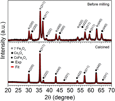 | ||
| Fig. 2 The XRD patterns, including the Rietveld refinement (red solid line) of the precursor powders before milling and the CoFe2O4 sample indexed with the (hkl) reflections of the spinel structure. | ||
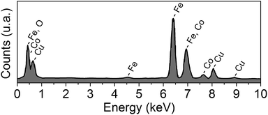
The EDS spectrum (Fig. 3) of the CoFe2O4 nanopowder shows the presence of Co, Fe, Cu and O. One can notice that, except for peaks related to Cu, no additional peaks due to impurities appear in the EDS spectrum. Table 1 shows the concentration of elements present in the sample, from which we can observe that the ratios of the elements slightly deviate from the ideal concentration.
| Element | Ideal (%) | Exp. (%) |
|---|---|---|
| Co | 34.53 | 32.82 |
| Fe | 65.47 | 67.18 |
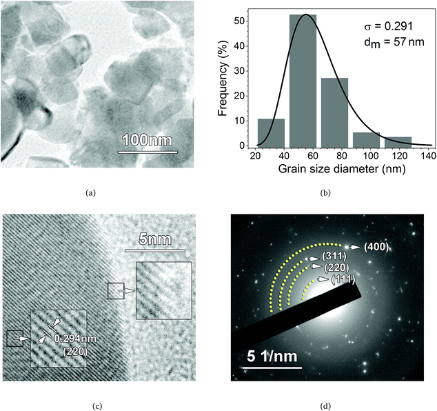
TEM images of the CoFe2O4 nanopowder are shown in Fig. 4. From the micrograph in Fig. 4(a), we can observe that the grains consist of agglomerates, with shapes that are not well defined, of nanoparticles without the presence of pores or fractures. The particle morphology is strongly affected by the ball milling process, which provides various shapes of nanoparticles during ferrite formation.23,24 The average grain size diameter (dm) is determined from the histogram size, shown in Fig. 4(b), using a log-normal distribution function. The parameters obtained from the fit (black solid line) were dm = 57 nm and σ = 0.291. Furthermore, the image in Fig. 4(c) clearly shows fringes separated by 0.294 nm, corresponding to the (220) crystalline planes of the CoFe2O4 spinel structure. In addition, in this figure, we can observe that the particles have well-ordered crystalline planes that extend to the particle boundaries. This makes us conclude that surface effects, such as an amorphous layer or second phases, are not present in our sample. The SAED pattern of the sample is shown in Fig. 4(d). According to this diffraction pattern, the measured lattice constant and the interplanar spacing (dhkl) are in agreement with those calculated from XRD analysis.
57Fe Mössbauer spectroscopy was performed at 12 K to determine the cation distribution in the CoFe2O4 structure. Fig. 5 depicts the Mössbauer spectrum of the precursor; a single sextet was used to fit the spectrum and the calculated hyperfine parameters were in close agreement with the γ-Fe2O4 phase.25 The Mössbauer spectrum of the calcined sample shows a single-phase and magnetically blocked sample with a two-site pattern, indicating the presence of Fe located in tetrahedral (A) and octahedral (B) sites. These components were fitted to a sextet and to a distribution of hyperfine magnetic field sextets, respectively. The hyperfine parameters obtained from the fits are in close agreement with results reported by Morrish26 and they indicate the presence of only Fe3+. The average hyperfine magnetic field, 〈HHf〉 = 54 T, for Fe at B-sites that is obtained from the fits is larger than the hyperfine field at A-sites (HHf = 49 T), as already reported. We have not observed any component related to a superparamagnetic phase or a second phase such as hematite or Fe oxy(hydroxide). These results are in agreement with the X-ray diffraction study. The chemical formula unit of the cobalt ferrites, (Co1−i2+Fei3+)[Coi2+Fe2−i3+]O4, can be determined from the degree of inversion parameter (i), which is defined as the fraction of Fe cations occupying tetrahedral sites. In the ferrite formula, cations enclosed in rounded and squared brackets are ions at the A and B sites, respectively. Ferrites are completely inverted when i = 1, partially inverted when 0 < i < 1, and normal spinel when i = 0. The degree of inversion can be calculated from the ratio of the relative absorption areas (RAAs); thus RAA (A)/RAA (B) = fA/fB·i/(2 − i), where fA/fB is the ratio of the recoilless fraction between tetrahedral and octahedral sites. At 5 K, the ratio fB/fA is equal to 0.96.27 By assuming that fA/fB at 12 K is similar to the value determined at 5 K, we have determined the inversion parameter of i = 0.88, and therefore, the distribution of cations will be (Co0.122+Fe0.883+)[Co0.882+Fe1.123+]O4.
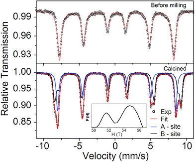 | ||
| Fig. 5 Mössbauer spectra recorded at 12 K for the before milling precursor and calcined powders. The inset is the histogram for the hyperfine magnetic field distribution for Fe at B-sites. | ||
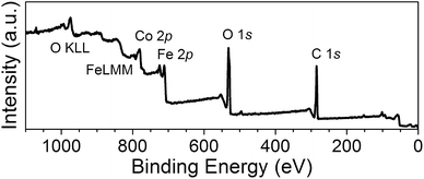
The surface chemical bonding states of the CoFe2O4 spinel oxide sample were characterized using XPS analysis. Three typical signals of the O 1s, Fe 2p and Co 2p core levels were detected from the survey scan plotted in Fig. 6. The high resolution spectrum of adventitious C 1s (284.6 eV) was used as the reference for the calibration of the binding energies of different elements. We have assumed in the fitting process that Fe and Co atoms occupy tetrahedral and octahedral sites based on XRD and Mössbauer spectra previously shown.
The high-resolution Fe 2p spectrum shown in Fig. 7 is composed of two spin–orbit doublets that are characteristic of Fe 2p3/2 (709.65 eV, Fe3+ in B-sites and 711.55 eV, Fe3+ in A-sites) and Fe 2p1/2 (723.08 eV, Fe3+ in B-sites and 725.73 eV, Fe3+ in A-sites) and the corresponding shake-up satellites (714.02, 718.57, 731.67, and 734.40 eV).28,29 However, the peak positions of the Fe 2p3/2 sub-spectra corresponding to Fe3+ in B-sites and its satellite coincide with the peak positions expected for Fe2+, i.e., 709.7 eV and 714.5 eV, respectively. Similarly, the binding energies of Fe2+ (2p1/2) and its satellite (723.3 and 730.1 eV)30 coincide with those corresponding to Fe3+ (2p1/2) in B-sites and its satellite. Therefore, the octahedral sites could be occupied either by Fe2+ or Fe3+ cations.
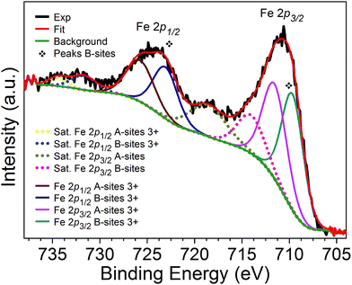 | ||
| Fig. 7 XPS high resolution spectrum of Fe 2p of the CoFe2O4 nanopowder. Dashed lines correspond to shake-up satellite peaks. | ||
The high-resolution Co 2p spectrum, depicted in Fig. 8, suggests the presence of Co2+ cations. This spectrum consists of two spin–orbit doublets Co 2p3/2 (779.40 eV, Co2+ in B-sites and 781.64 eV, Co2+ in A-sites) and Co 2p1/2 (794.95 eV, Co2+ in B-sites and 796.32 eV, Co2+ in A-sites) and the corresponding shake-up satellites (784.80, 718.57, 801.77, and 803.77 eV).28,29 Co3+ occupying octahedral and tetrahedral sites is expected to exhibit peaks centered at 783.3 eV and 798.5 eV, respectively (see the dashed arrows in Fig. 8). Note that the high-resolution spectrum obtained for Co 2p does not exhibit a defined peak around the Co3+ A-site position (798.5 eV). Therefore, it can be concluded that only Co2+ species are present in this sample. These results are complementary to those obtained by XRD and Mössbauer spectroscopy and supports the interpretation that the peaks observed in Fig. 7 are due to Fe3+ in tetrahedral and octahedral sites. Hence, only Fe3+ is present in this sample.
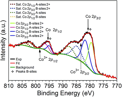 | ||
| Fig. 8 XPS high resolution spectra of Co 2p of the CoFe2O4 nanopowder. Dashed arrows indicate the expected values29 of the binding energies of the Co3+ species in octahedral (783.3 eV) and tetrahedral sites (798.5 eV). Dashed lines correspond to shake-up satellite peaks. | ||
The Fe and Co 2p and shake-up satellite peaks confirmed the Fe and Co oxidation states inside the prepared CoFe2O4 nanopowder. These results demonstrate that the surface of the CoFe2O4 nanopowder has a composition containing Fe3+ and Co2+ species characteristic of the CoFe2O4 and indicate, in addition, the presence of Fe and Co in the octahedral and tetrahedral sites. Area peaks analysis revealed an inversion parameter of i = 0.94.
5.2 Magnetic analysis
Before performing an analysis of the experimental magnetic data, let us describe the theoretical approach employed in this work.A topic of interest in the literature is the study of the roles of the dipolar interaction and magneto-crystalline anisotropy in influencing the magnetic properties of the system. In this regard, we study the influence of the dipolar field in granular systems presenting an easy-plane magneto-crystalline anisotropy using numerical simulations. Bearing this motivation in mind, we have performed numerical simulations of granular systems presenting easy-plane magneto-crystalline anisotropy with K1 > 0 and a = 0. The results for N = 2000 particles, σ = 0.3, and different values of c/c0 are depicted in Fig. 9. Our results indicate that, as the dipolar field increases (by decreasing c0 and keeping c fixed), the so-called wasp-waisted hysteresis loop is produced.
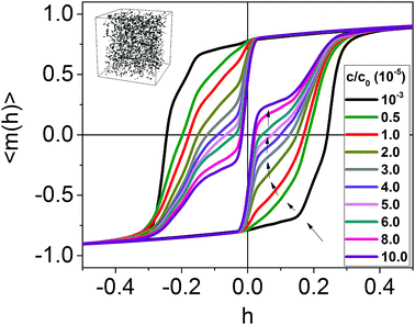 | ||
| Fig. 9 Reduced magnetic hysteresis curves for different values of c/c0, with N = 2000 and σ = 0.3. The black arrows indicate the formation of “jumps” in the reduced hysteresis as c/c0 increases. | ||
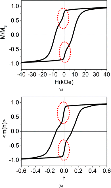
Now, we present the experimental results of static magnetic hysteresis for our CoFe2O4 sample at a low temperature (T = 5 K). We must emphasize that our sample simply does not fit into any of the previously depicted scenarios, although it presents a wasp-waisted hysteresis loop (see Fig. 10(a)). For example, from the XRD data, only a single crystalline phase, namely a spinel structure, is observed. Additionally, the TEM images and EDS analysis show a high-purity CoFe2O4 compound, with cation concentrations slightly deviating from the theoretical stoichiometry, discarding the existence of other magnetic phases. The TEM images also show a set of ordered crystalline planes, which extend to the surface of the particles, thus resulting in negligible surface effects. The Mössbauer spectroscopy results show an inverse spinel parameter of i = 0.88, which means that there is no competition between AFM and FM coexisting magnetic ordered phases in the spinel structure, contrary to what was observed by Rahman et al.3 XPS analysis provides further characterization confirming the presence of only Co2+ and Fe3+ cations in the sample, compatible to the single-phase CoFe2O4 spinel structure and, besides, area peak analysis indicates an inversion parameter close to that which was found by Mössbauer spectroscopy (i = 0.94). The spin re-orientation at a low temperature being due to canted spins on the surface of the nanoparticles is very improbable because the surface/volume ratio of our particles is very small. The present scenario of a mixture of multi-domain and single-domain particles is not discarded; however, the high experimental squareness (mr = Mr/M(Hmax) = 0.79) makes a dominant multi-domain phase leading to the wasp-waisted behavior of magnetization unlikely. A pure multi-domain phase system should exhibit a very low squareness compared to the single-domain phase.2 In this regard, it is likely that a residual multi-domain phase will favor a smaller coercivity field value.
In Fig. 10(b), we show theoretical results for the reduced magnetic hysteresis. We performed a numerical simulation with 2000 particles, where c/c0 = 3.5 × 10⁻⁵, a = −0.7, and σ = 0.3. The squareness and reduced coercivity are mr = 0.703 and hc = 0.108, respectively. If we compare with the experimental data, we obtain Ms = 89.30 emu g−1, which is close to the bulk value of CoFe2O4.31 This supports the argument that surface effects are not relevant in our sample. Since we use c = 10−2, corresponding to c0 = 285.71, the anisotropic field Hk1 = 134.4 kOe, and consequently, K1 = 3.16 × 10⁷ erg per cm3 and K2 = −2.21 × 10⁷ erg per cm3. Both values of the anisotropy constants are compatible with experimental values of similar samples produced by other methods and those determined from the law of approach to saturation.32,33 From Hk1, we can calculate the coercivity using Hc = hcHk1, which gives Hc = 14.5 kOe. This theoretical value is larger than the experimental result obtained in the present work, which is Hc = 8.4 kOe. This may be the effect of a residual multi-domain phase, which tends to reduce the coercivity values.2 We must note an interesting implication about the magneto-crystalline configuration adopted in our model. The fact that the uniaxial symmetry corroborates with the experiment indicates that our sample exhibits, at 5 K, a structure deviating from cubic symmetry. This result is in agreement with the tetragonal symmetry previously reported for cobalt ferrite.34,35
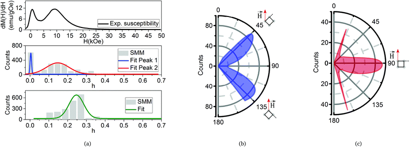
To obtain greater insight into the origin of the wasp-waisted hysteresis loop, we determine, from our model, the number of switched magnetic moments (SMMs) as a function of the reduced applied magnetic field h, i.e., we plot a histogram of the number of flipped magnetic moments for each value of the reduced applied magnetic field. In Fig. 11(a) (top), we show the results for the experimental isothermal magnetic susceptibility. We can clearly observe the presence of two peaks, instead of the usual single-peak pattern, indicating that our sample presents two switching field distributions centered at approximately H = 0.63 kOe (first peak) and H = 9.10 kOe (second peak). In Fig. 11(a) (middle), we present the theoretical plot of SMMs as a function of h. We can see that the SMMs present a behavior that is quite similar to the experimental susceptibility, with a two-peak pattern. This result is obtained from the combination of the dipolar field/concentration ratio and the easy-plane anisotropy, which originates from the two well-defined switching field distributions. In Fig. 11(a) (bottom), we present the plot of the SMMs as a function of h, but with c/c0 = 10−8. We can infer from Fig. 11(a) (bottom) that the absence of the dipolar field destroys the two-peak pattern, and the usual single-peak pattern is recovered. We conclude that the double-peak pattern is a signature of the easy-plane anisotropy and dipolar field interaction.
Fig. 11(b) and (c) show the polar distribution of θu related to the particles that were flipped around the peaks shown in Fig. 11(a). The polar distribution of SMMs around the first peak (solid blue line) is illustrated in Fig. 11(b). We can observe that the main contribution for the first peak comes from the particles with θu ≈ π/4 and θu ≈ 3π/4. The polar distribution of SMMs around the second peak (solid red line) is illustrated in Fig. 11(c). Now, the main contribution for the second peak comes from the particles with θu ≈ π/2.
Therefore, even with the same anisotropy constant, the combination of the dipolar field and easy-plane configuration leads to a wasp-waisted-like magnetic hysteresis loop by creating two well-defined peaks in the switching field distribution. In contrast to the work of Chithra et al.,4 our sample does not present two types of particles with different magnetic anisotropies, and this is well established by the structural and magnetic characterization previously described. Chithra et al. studied samples with higher values of coercivity (Hc = 18.69 kOe at T = 10 K) than our sample and an average grain size of ∼22 nm. In this case, this average grain size indicates that the nanoparticles are almost entirely in a single-domain structure. This is compatible with our simulations and interpretation. Since we only consider the single-domain phase, the theoretical result for the coercivity is higher than experimental one; our sample still presents a residual multi-domain phase due to the average grain size of ∼57 nm which tends to diminish the coercivity.
Let us investigate the trajectory of a particular magnetic moment in two specific cases: (i) c/c0 = 3.5 × 10⁻⁵ (theoretical result in agreement with the experimental results) and (ii) c/c0 = 10−8, corresponding to a very diluted case (no dipolar interaction). Let us take, for example, a particle with θu = 44.93° and ϕu = 84.24° around the center of the simulation box. In Fig. 12(a) and (c), we have the reduced magnetic hysteresis loop for c/c0 = 10−8 and c/c0 = 3.5 × 10⁻⁵, respectively. We clearly observe a strong reduction in coercivity hc, from the first case to the second case, due to the presence of the dipolar field. To facilitate the visualization of the changes in the magnetization orientation, we labeled a few steps along the low branch of the hysteresis loop in the interval from −hsat to hsat in Fig. 12(b) (zero dipolar field) and 12(d) (dipolar field). The reduced coercivity decreases from 0.226 to 0.047. If we consider Hk1 = 134.4 kOe (obtained from the numerical calculation), we obtain the corresponding coercivities 30.3 kOe and 6.31 kOe, respectively. We may interpret this huge reduction in the coercivity as a consequence of the symmetry and degeneracy of the easy-plane anisotropy. In contrast to easy-axis symmetry, which has only one direction of equilibrium and where the transition over the surface of the energy is attenuated, easy-plane symmetry presents a plane of equilibrium orientation of the magnetization, and the transition over the surface of energy is facilitated. The blue ellipses indicated in Fig. 12(a) and (b) show the path of the magnetization that was suppressed by the dipolar field.
6 Conclusions
We have shown that the magnetization of easy-plane anisotropy single-domain particles that are affected by dipolar interactions has a field dependence in a wasp-waisted-like hysteresis curve. The number of switched magnetic particles as a function of the field indicated that the easy-plane anisotropy and dipolar interaction favor two switching fields, and these are related to the particle concentration. Choosing a particular nanoparticle and comparing the very diluted case with c/c0 = 3.5 × 10⁻⁵ we note a strong decrease in coercivity. These results presented trends that are in agreement with the experimental magnetization curves from cobalt ferrite prepared using annealed ball-milled nanoparticles. The proposed physical model is suitable for explaining the wasp-waisted behavior of magnetic hysteresis curves.Acknowledgements
The authors thank the national agencies CAPES, CNPq, and INCT of Space Studies for financial support.References
- P. J. Wasilewski, Earth Planet. Sci. Lett., 1973, 20, 67 CrossRef CAS.
- A. P. Roberts, et al., J. Geophys. Res.: Solid Earth, 1995, 100, 17909 CrossRef.
- A. U. Rahman, et al., J. Nanopart. Res., 2014, 16, 1 CrossRef.
- M. Chithra, et al., J. Magn. Magn. Mater., 2016, 401, 1 CrossRef CAS.
- Q. Song and Z. J. Zhang, J. Am. Chem. Soc., 2012, 134, 10182 CrossRef CAS PubMed.
- J. Fu, et al., Nanoscale, 2012, 4, 3932 RSC.
- Z. Zhang, et al., Adv. Mater., 2005, 17, 1415–1419 CrossRef CAS.
- Z. Wang, et al., J. Phys. Chem. C, 2008, 112, 15171 CAS.
- S. T. Xu, et al., Nanoscale, 2015, 7, 6520 RSC.
- D. C. Lee, et al., J. Phys. Chem. B, 2006, 110, 11160 CrossRef CAS PubMed.
- M. Woińska, et al., Phys. Rev. B: Condens. Matter Mater. Phys., 2013, 88, 144421 CrossRef.
- M. El-Hilo, et al., J. Appl. Phys., 1998, 84, 5114 CrossRef CAS.
- J. Garcia-Otero, et al., J. Appl. Phys., 2000, 87, 7376 CrossRef CAS.
- J. Garcia-Otero, et al., Phys. Rev. Lett., 2000, 84, 167 CrossRef CAS PubMed.
- D. Kechrakos and K. N. Trohidou, Phys. Rev. B: Condens. Matter Mater. Phys., 1998, 58, 12169 CrossRef CAS.
- H. T. Yang, et al., Appl. Phys. Lett., 2011, 98, 153112 CrossRef.
- B. D. Cullity and S. R. Stock, Elements of X-ray diffraction, Prentice Hall, 2001 Search PubMed.
- M. Getzlaff, Fundamentals of Magnetism, Springer, Berlin, Heidelberg, 2007 Search PubMed.
- V. Schaller, et al., J. Magn. Magn. Mater., 2009, 321, 1400 CrossRef CAS.
- Z. Mao, et al., J. Magn. Magn. Mater., 2008, 320, 2335 CrossRef CAS.
- V. Russier, J. Appl. Phys., 2001, 89, 1287 CrossRef CAS.
- B. D. Cullity and C. D. Graham, Introduction to magnetic materials, Wiley-IEEE Press, 2008 Search PubMed.
- C. Suryanarayana, Prog. Mater. Sci., 2001, 46, 1 CrossRef CAS.
- L. Kumar, et al., Int. Nano Lett., 2013, 3, 1 CrossRef.
- R. M. Cornell and U. Schwertmann, The Iron Oxides, Wiley-VCH, 2nd edn, 2003 Search PubMed.
- G. A. Sawatzky, et al., Phys. Rev., 1969, 187, 747 CrossRef CAS.
- R. W. Grant, et al., J. Appl. Phys., 1967, 38, 1455 CrossRef CAS.
- Z. Zhou, et al., Appl. Surf. Sci., 2008, 254, 6972 CrossRef CAS.
- T.-C. Lin, et al., Appl. Surf. Sci., 1997, 119, 83 CrossRef CAS.
- A. Demund, et al., Surf. Interface Anal., 2008, 40, 27 CrossRef CAS.
- J. Smit and H. P. J. Wijn, Ferrites, Philips’ Technical Library, 1959 Search PubMed.
- Y. Melikhov, et al., J. Appl. Phys., 2006, 99, 08R102 CrossRef.
- B. G. Toksha, et al., Solid State Commun., 2008, 147, 479 CrossRef CAS.
- H. P. Rooksby and B. T. M. Willis, Nature, 1953, 172, 1054 CrossRef CAS.
- S. Yang and X. Ren, Phys. Rev. B: Condens. Matter Mater. Phys., 2008, 77, 014407 CrossRef.
| This journal is © The Royal Society of Chemistry 2017 |


