 Open Access Article
Creative Commons Attribution 3.0 Unported Licence
Asymmetric geometry composites arranged between parallel aligned and interconnected graphene structures for highly efficient thermal rectification†
Xiaomin Guab,
Shudong Zhang *a,
Mengya Shangab,
Tingting Zhaoa,
Nian Lia,
Haifeng Liab and
Zhenyang Wang*a
aInstitute of Intelligent Machines, Chinese Academy of Sciences, Hefei, Anhui 230031, China. E-mail: sdzhang@iim.ac.cn; zywang@iim.ac.cn
bDepartment of Chemistry, University of Science & Technology of China, Hefei, Anhui 230026, China
First published on 8th February 2017
Abstract
A novel framework of binary asymmetric geometry composites was arranged between parallelly aligned and interconnected, microcosmic, graphene structures. The greater number of efficient, heat transfer channels in interconnected graphene networks (one end) than in the parallelly aligned structures (another end) resulted in both ends of the thermal conductivity saltation. Therefore, this resulted in the adjustment of the thermal rectification of graphene composites to control the direction of heat flow.
Thermal rectification, a special heat transfer mode, is an interesting phenomenon in which heat transport is related to the temperature gradient or the direction of heat flow. Thermal rectification can lead to a greater heat flow in one direction than in another one.1,2 Thus, in the last decade, the phenomenon of thermal rectification has attracted considerable interest for its potential application in thermal management of electronics and energy savings. There are currently several general approaches that can potentially result in rectifying behaviour or realize thermal rectification, such as temperature dependent thermal conductivity,2–5 interfacial thermal resistance,6–8 asymmetric geometries,3,4,9–12 mass difference and size dependence. Moreover, the asymmetric structure is expected to be a behavior of thermal rectification at both macro scale and nanoscale. For example, at the macro scale, numerical calculations and experiments have demonstrated that two-segment bulk materials with different thermal conductivity dependencies on temperature have thermal rectification characteristics.13 Moreover, thermal rectification in bulk asymmetric structures have been investigated to determine the shape dependence of the thermal rectification via both theoretical calculations and experiments.3 Recently, it has been reported that the single asymmetric material of reduced graphene oxide (rGO) can produce a heat rectification phenomenon at the macroscopic scale based on the dependencies of thermal conductivity of rGO on temperatures.9 At the nanoscale, the thermal rectification effect of the different asymmetric structures, including asymmetric carbon nanotubes,1,5,7,14–19 graphene nanoribbons,11,20–24 nanoporous silicon,25 and graphene,4,6,9,10,16,26 was studied in-depth, and simulated using molecular dynamics theory and classical nonequilibrium simulation. The abovementioned research studies have shown that the geometric asymmetry was a very valid way to increase the rectification ratio. In addition, the benefit of employing an asymmetric structure is that the thermal rectifier device can be constructed with a single material system.
Graphene has drawn great attention because of its mechanical strength and outstanding high thermal conductivity (∼5000 W m−1 K−1).27–29 Its conjugated molecular planar structure allows high, in-plane thermal conductivity.30,31 In addition, graphene sheets with an ultrahigh aspect ratio are facially constructed to form bulk shaped materials with a different microscale structure, including parallel and vertically aligned graphene layers and interconnected graphene networks. In addition to the intrinsic properties of graphene, the performance of the entire bulk graphene-shaped material is also affected by a graphene-unit aligned orientation. Therefore, graphene is considered to be a promising material to construct a thermal rectifier device.31,32 It is helpful to both practically construct a thermal rectifier and explore the possible thermal rectification of various nanostructures, which are facing great difficulties. Herein, we introduce a general strategy to achieve a novel framework of binary, asymmetric, geometry composites arranged between parallelly aligned and interconnected graphene in a single material, which has two ends with different microcosmic graphene structures. In current asymmetric, geometry composites, the conjugated molecular plane of graphene can provide a large contact area with the PEG polymer matrix compared with other 0-D or 1-D materials, which is of benefit to adjust the graphene filler orientation. Moreover, the novel binary, asymmetric geometry composite can generate a more efficient heat rectification phenomenon. The larger number of efficient heat transfer channels in interconnected graphene networks (one end) than in parallel aligned structures (another end) result in both ends of the thermal conductivity transformation, adjusting the thermal rectification with the coefficient up to 1.44. The thermal rectification coefficient was increased by 12.5% compared to that of the macroscopic asymmetric structure of the reduced graphene oxide paper.9 This value can be adjusted in light of controlling the length ratio of parallelly aligned and interconnected microcosmic graphene.
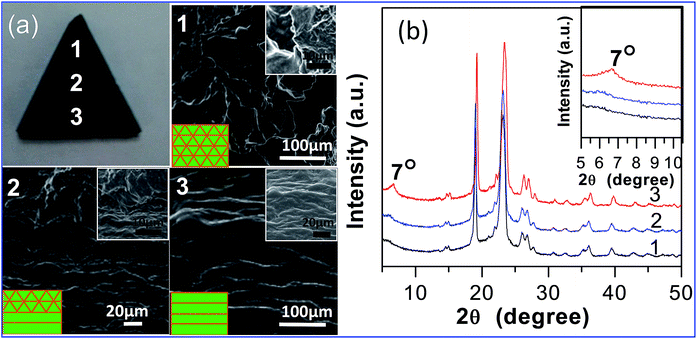
In this study, in order to achieve a highly efficient thermal rectification, we combined the advantages of asymmetric geometry structure and different microstructures to design a novel framework of binary asymmetric geometry composites. As illustrated in Fig. 1, the composite was designed as an asymmetric triangle geometry. A nanoscale asymmetric structure was composed of parallelly aligned and interconnected graphene, which constituted two ends with a different microcosmic framework. In addition, the micro asymmetric structure can be conveniently controlled in light of adjusting the length ratio of interconnected graphene and parallel aligned graphene. We demonstrated the abovementioned design concept by experimental approaches and examples. First, the interconnected graphene/polyethylene glycol composites (i-G/PEGs) and parallelly aligned graphene/polyethylene glycol composites (p-G/PEGs) were prepared by simple, complete mixing of the PEG and graphene suspension and air-drying methods under ambient temperature (ESI). Second, interconnected and parallel aligned G/PEGs were cross-linked by PEG to fit together. Finally, the samples could be assembled into various shapes, such as a triangle shape (Fig. 2(a)). The low and high magnification of the SEM image indicates that i-G/PEGs have a disordered morphology with an interconnected network frame (Fig. 2(a)-1, upper inset). The morphology contains surface folds, which are evidently different from the p-G/PEGs with a parallelly aligned structure (Fig. 2(a)-3, upper inset). In the cross-linked position of the different microstructure (Fig. 2(a)-3, upper inset), an evident difference can be observed in low and high magnification of the SEM image. The XRD patterns of the p-G/PEG, i-G/PEGs and the corresponding composite structure are evidently distinct as shown in Fig. 2(b). The i-G/PEGs did not have a sharp peak at 7°, demonstrating that the graphene sheets did not pack into an ordered, layered structure, which corresponds to the results of SEM images (Fig. 2(a)-1). Furthermore, the cross-linked position of the complex morphology can be clearly observed in the SEM image (Fig. 2(a)-2), which displays a composite structure of the network framework (on the top) and parallel layer-by-layer arrangement (on the bottom).
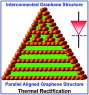 | ||
| Fig. 1 Simple schematic of a novel framework of binary asymmetric triangle geometry composites composed between parallel aligned and interconnected microcosmic graphene structures. | ||
The asymmetric structure can promote the generation of thermal rectification.3,10,12,21 Therefore, the obtained binary, triangular geometry composites arranged between a parallelly aligned and interconnected graphene structure were studied. The length ratio of the network and layered structure in composites was 1![[thin space (1/6-em)]](https://www.rsc.org/images/entities/char_2009.gif) :
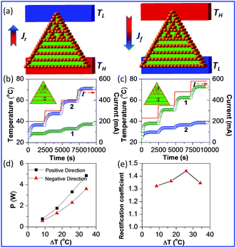
:![[thin space (1/6-em)]](https://www.rsc.org/images/entities/char_2009.gif) 1 (Fig. 1). Herein, we define that the positive direction of heat flow is from the top to the bottom of the triangular G/PEGs. In addition, heat power can be set as P+ when the measurement system reaches the non-equilibrium stationary state. In the negative direction, heat power was recorded as P−. The conceptual diagram of thermal rectification with the triangular G/PEGs is shown in Fig. 3(a), and the i-G/PEGs are located at the top. The heat flows from high temperature TH to low temperature TL as revealed by the direction of the arrows. The forward heat flux Jf is the heat that flows from the interconnected network structure to the layered structure, while the reverse direction is defined as Jr. The temperature variations with time are presented in Fig. 3(b) (negative direction) and Fig. 3(c) (positive direction). The temperature in points 1 and 2 increased with increasing current. The same temperature bias is in Fig. 3(b) and (c), then, ΔT = |T2 − T1| and recording the corresponding current. Moreover, the heat power (Fig. 3(d)) and thermal rectification coefficient (Fig. 3(e)) vary with the temperature bias. Heat power (P) can be defined as
1 (Fig. 1). Herein, we define that the positive direction of heat flow is from the top to the bottom of the triangular G/PEGs. In addition, heat power can be set as P+ when the measurement system reaches the non-equilibrium stationary state. In the negative direction, heat power was recorded as P−. The conceptual diagram of thermal rectification with the triangular G/PEGs is shown in Fig. 3(a), and the i-G/PEGs are located at the top. The heat flows from high temperature TH to low temperature TL as revealed by the direction of the arrows. The forward heat flux Jf is the heat that flows from the interconnected network structure to the layered structure, while the reverse direction is defined as Jr. The temperature variations with time are presented in Fig. 3(b) (negative direction) and Fig. 3(c) (positive direction). The temperature in points 1 and 2 increased with increasing current. The same temperature bias is in Fig. 3(b) and (c), then, ΔT = |T2 − T1| and recording the corresponding current. Moreover, the heat power (Fig. 3(d)) and thermal rectification coefficient (Fig. 3(e)) vary with the temperature bias. Heat power (P) can be defined as
| P = rI2 | (1) |
 | (2) |
As implied in Fig. 3(e), R can reach the largest value of 1.44 when ΔT = 25.9 °C. In the i-G/PEGs, its network structure has a variety of heat transfer pathways, meaning it has a rather good heat channel when the heat flux is flowing and the heat transfer mode is very effective. However, the thermal channel of the p-G/PEGs will be hampered by heat transfer, meaning the heat flux can only pass through the surface of graphene. In order to further explain the underlying mechanism of thermal rectification of binary, asymmetric geometry composites, the thermal conductivities of p-G/PEGs and i-G/PEGs were measured. Results show that the thermal conductivity of i-G/PEGs is higher than that of p-G/PEGs. For example, the thermal conductivity of i-G/PEGs is 0.2870 W m−1 K−1, while that for p-G/PEGs is 0.2045 W m−1 K−1 under ambient conditions. When i-G/PEGs and p-G/PEGs were constructed and integrated together, the heat flow generated in the positive and negative direction is obviously different due to the difference of the thermal conductivity distribution in i-G/PEGs and p-G/PEGs. This is consistent with the experimental results of the rGO with binary composites that indicate the larger the discrepancy of the thermal conductivity of two different materials, the better the thermal rectification effect.33 In addition, the results for the thermal rectification phenomenon of the rectangular structure of binary asymmetric G/PEGs can be found in the appendix (Fig. S4 of ESI†).
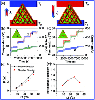
In order to better validate the effectiveness of our design of the asymmetric geometry G/PEGs on the thermal rectification effect, comparative tests were conducted. The thermal rectification phenomenon of the single, interconnected structure G/PEGs with higher thermal conductivity was investigated. Fig. 4(a) is the conceptual diagram of the direction of heat flow with a sample of netlike G/PEGs. Fig. 4(b) and (c) in the negative and positive direction, respectively, show the transformation of temperature and current over time for points 1 and 2. The magnitude of heat power in the positive direction (P+) is particularly larger than that in the negative direction (P−), as shown in Fig. 4(d). As the temperature bias increases, P+ and P− are monotonically increased. In Fig. 4(e), the thermal rectification coefficient R can be up to a maximum value of 1.27 when ΔT = 25.7 °C.
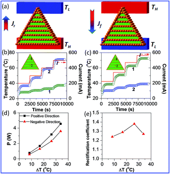
Moreover, the thermal rectification phenomenon of the single parallelly aligned structure G/PEGs with lower thermal conductivity was also explored. Fig. 5(a) is a simple simulation of the direction of heat flow with parallel-layer composites. Similarly, layered G/PEGs were constructed into triangular structures according to the same research methods used to prepare i-G/PEGs. Fig. 5(b) shows the temperature and current variations with time in points 1 and 2 in the negative and positive directions (Fig. 5(c)). As shown in Fig. 5(d), P+ increased more than P−. The thermal rectification coefficient has a maximum value of R = 1.38 when ΔT = 26.3 °C, as shown in Fig. 5(e). Considering all the experimental results, it is clear that the thermal rectification coefficients of parallel-layer G/PEGs are even larger than interconnected composites.
In recent years, thermomass theory has been used to explain the influence of the asymmetrical structures on thermal rectification.34,35 According to the mass–energy equivalence of Einstein, which indicates that thermal energy has the equivalent mass and heat transfer processes can be regarded as flowing processes of thermomass. In the flowing process of thermomass, the inertia of motion effect produces acceleration or deceleration. When the heat flux of QH transmits from the cross-sectional area of A1 to the cross-sectional area of A2, the formula of equivalent thermal resistance is expressed in eqn (3):
 | (3) |
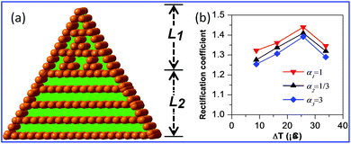
From the results mentioned above, the binary, asymmetric geometry composites arranged between parallelly aligned and interconnected graphene can generate a more efficient heat rectification effect. Nevertheless, the thermal rectification coefficient is significantly diverse in light of adjusting the length ratio of parallel aligned and interconnected graphene composites. In Fig. 6(a), L1 and L2 are respectively the length of interconnected and parallel aligned graphene structures where α = L1/L2. As shown in Fig. 6(b), with the increased temperature bias, a thermal rectification value with a different length ratio was also distinct. The largest thermal rectification value of R = 1.44 was obtained when L1/L2 = 1![[thin space (1/6-em)]](https://www.rsc.org/images/entities/char_2009.gif) :
:![[thin space (1/6-em)]](https://www.rsc.org/images/entities/char_2009.gif) 1 at ΔT = 25.9 °C.
1 at ΔT = 25.9 °C.
Conclusion
In summary, we have successfully shown, for the first time, the thermal rectification phenomena of the binary, asymmetric geometry composites arranged between parallel aligned and interconnected graphene. The greater amount of efficient, heat transfer channels in interconnected, graphene networks than in parallelly aligned structures result in both ends of the thermal conductivity saltation. Thus, the triangular structure of binary, asymmetric geometry composites, possessing both a macro- and micro-asymmetric structure, have thermal rectification coefficients up to 1.44. This value can be adjusted by controlling the length ratio of parallel aligned and interconnected graphene. Our research based on G/PEG can produce a highly efficient heat rectification phenomenon under ambient temperature. Furthermore, the current simple method can be extended to realize the thermal rectification system by asymmetric structures, mass differences and size dependence. Therefore, potential applications include thermal management of electronics, intelligent temperature control and energy saving.Acknowledgements
This study was financially supported by the National Natural Science Foundation of China (No. U1432132, 61605222) and the Major/Innovative Program of the Development Foundation of Hefei Center for Physical Science and Technology (2014FXZY001).Notes and references
- G. C. Loh, E. T. Teo and B. K. Tay, J. Appl. Phys., 2012, 112, 103515 CrossRef.
- W. Kobayashi, D. Sawaki, T. Omura, T. Katsufuji, Y. Moritomo and I. Terasaki, Appl. Phys. Express, 2012, 5, 027302 CrossRef.
- D. Sawaki, W. Kobayashi, Y. Moritomo and I. Terasaki, Appl. Phys. Lett., 2011, 98, 3 CrossRef.
- G. Zhang and H. Zhang, Nanoscale, 2011, 3, 4604–4607 RSC.
- M. Alaghemandi, E. Algaer, M. C. Bohm and F. Muller-Plathe, Nanotechnology, 2009, 20, 115704 CrossRef PubMed.
- W. Xu, G. Zhang and B. Li, J. Appl. Phys., 2014, 116, 134303 CrossRef.
- A. K. Vallabhaneni, B. Qiu, J. Hu, Y. P. Chen, A. K. Roy and X. Ruan, J. Appl. Phys., 2013, 113, 064311 CrossRef.
- Q. X. Pei, Y. W. Zhang, Z. D. Sha and V. B. Shenoy, Appl. Phys. Lett., 2012, 100, 101901 CrossRef.
- H. Tian, D. Xie, Y. Yang, T. L. Ren, G. Zhang, Y. F. Wang, C. J. Zhou, P. G. Peng, L. G. Wang and L. T. Liu, Sci. Rep., 2012, 2, 523 Search PubMed.
- J. Cheh and H. Zhao, J. Stat. Mech.: Theory Exp., 2012, 2012, P06011 Search PubMed.
- N. Yang, G. Zhang and B. Li, Appl. Phys. Lett., 2009, 95, 033107 CrossRef.
- J. Lee, V. Varshney, A. K. Roy, J. B. Ferguson and B. L. Farmer, Nano Lett., 2012, 12, 3491–3496 CrossRef CAS PubMed.
- W. Kobayashi, Y. Teraoka and I. Terasaki, Appl. Phys. Lett., 2009, 95, 3 CrossRef.
- X. Zhang, M. Hu and D. Tang, J. Appl. Phys., 2013, 113, 194307 CrossRef.
- K. Gordiz, S. M. Vaez Allaei and F. Kowsary, Appl. Phys. Lett., 2011, 99, 251901 CrossRef.
- K. Bui, H. Nguyen, C. Cousin, A. Striolo and D. V. Papavassiliou, J. Phys. Chem. C, 2012, 116, 4449–4454 CAS.
- K. Takahashi, M. Inoue and Y. Ito, Jpn. J. Appl. Phys., 2010, 49, 02BD12 Search PubMed.
- X. Ni, G. Zhang and B. Li, J. Phys.: Condens. Matter, 2011, 23, 215301 CrossRef PubMed.
- S. Pal and I. K. Puri, Nanotechnology, 2014, 25, 345401 CrossRef PubMed.
- Y. Wang, S. Chen and X. Ruan, Appl. Phys. Lett., 2012, 100, 163101 CrossRef.
- W. R. Zhong, W. H. Huang, X. R. Deng and B. Q. Ai, Appl. Phys. Lett., 2011, 99, 193104 CrossRef.
- J. Hu, X. Ruan and Y. P. Chen, Int. J. Thermophys., 2012, 33, 986–991 CrossRef CAS.
- S. Pal and I. K. Puri, Small, 2015, 11, 2910–2917 CrossRef CAS PubMed.
- H. Fan, L. Deng, X. Yuan, J. Guo, X. Li and P. Yang, RSC Adv., 2015, 5, 38001–38005 RSC.
- M. Criado-Sancho, F. X. Alvarez and D. Jou, J. Appl. Phys., 2013, 114, 053512 CrossRef.
- P. Yang, X. Li, H. Yang, X. Wang, Y. Tang and X. Yuan, Appl. Phys. A, 2013, 112, 759–765 CrossRef CAS.
- C. Li and G. Shi, Nanoscale, 2012, 4, 5549–5563 RSC.
- K. X. Sheng, Y. X. Xu, C. Li and G. Q. Shi, New Res. Carbon Mater., 2011, 26, 9–15 CrossRef CAS.
- L. Ren, K. N. Hui, K. S. Hui, Y. Liu, X. Qi, J. Zhong, Y. Du and J. Yang, Sci. Rep., 2015, 5, 14229 CrossRef CAS PubMed.
- X. J. Liu, G. Zhang and Y. W. Zhang, J. Phys. Chem. C, 2014, 118, 12541 CAS.
- X. J. Liu, G. Zhang and Y. W. Zhang, Nano Lett., 2016, 16, 4954 CrossRef CAS PubMed.
- X. J. Liu, G. Zhang and Y. W. Zhang, Nano Res., 2015, 8, 2755 CrossRef CAS.
- R. J. Chen, Y. L. Cui, H. Tian, R. M. Yao, Z. P. Liu, Y. Shu, C. Li, Y. Yang, T. L. Ren, G. Zhang and R. Q. Zou, Sci. Rep., 2015, 5, 8884 CrossRef CAS PubMed.
- M. Wang and Z. Y. Guo, Phys. Lett. A, 2010, 374, 4312–4315 CrossRef CAS.
- Y. Dong, B. Y. Cao and Z. Y. Guo, J. Appl. Phys., 2011, 110, 063504 CrossRef.
Footnote |
| † Electronic supplementary information (ESI) available: Experimental section and additional material characterization. See DOI: 10.1039/c7ra00118e |
| This journal is © The Royal Society of Chemistry 2017 |

