 Open Access Article
Creative Commons Attribution 3.0 Unported Licence
An electrostatic nanosecond switch in a nanoscale water channel†
Dongqin Zheng ,
Jianhui He,
Jiamei Feng,
Jiale Wen and
Weirong Zhong*
Siyuan Laboratory, Guangzhou Key Laboratory of Vacuum Coating Technologies and New Energy Materials, Department of Physics, Jinan University, Guangzhou 510632, China. E-mail: wrzhong@hotmail.com
First published on 22nd March 2017
Abstract
We proposed a nanoscale water switch composed of CNTs. A capped CNT with potassium ions in it may move under an external electric field, just like a piston. We can control the switch toggle between the open and closed states only by changing the direction of the external electric field. Molecular dynamics (MD) was used to simulate the performance of the switch. The results show that this device may act well as a switch. The response speed of the switch reaches the nanosecond level. The stability of the piston position is also investigated.
1. Introductions
Fluid diffusion and transportation through nano-channels or nano-pores have attracted a lot of attention in recent years.1–3 How to transport and control the fluid molecules in nano-channels is the ultimate goal of nanofluidics. Among these studies, the study of water control plays an important role because of its wide application in water purification,4 gaseous separation5 and bio-nanotechnology.6 Although water flow control devices have been well developed in the macroscopic scale, it is much more difficult in the nanoscale. However, such research opens the possibility of developing nanoscale devices in which the water flow can be manipulated.Carbon nanotubes (CNTs) have often been employed as molecular channels because of their one-dimensional structure and the unusual properties of the fluid transportation. In 2001, Hummer et al. found that water can transport through carbon nanotubes (CNTs).7 They have observed that a small reduction of the nanotube-water attractive potential produced a large change in the water occupancy of the channel with two-state transitions between empty and filled states. Usually, electrical control is a convenient manipulation for carbon nanotubes,8,9 which can be realized by placing electrodes along the walls of carbon nanotubes.10
In the macroscopic world, the piston structure was widely used in controlling water flow.11–16 For small scale channels, a water switch is still an unresolved problem. In this paper, we proposed a nanoscale piston structure by using a T-type CNT and a capped CNT, in which one or two potassium ions are caged. The piston can be controlled by a static electric field, and therefore it can control the water flow in the nano-channel.
To build the structure mentioned in this paper, two issues cannot be disregarded. One is the technological difficulty to fabricate the capped CNTs and fullerene. Recently, many researched focus on this problem through physical and chemical methods.17,18 Another issue is the structure stability of capped fullerene, which are also widely studied.19–21 Based on these studies, building a T-type CNTs imbedded a fullerene is feasible.
2. Models
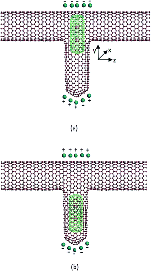
In the research field of nano-channel transport, most researchers employ CNTs as their channel model, because CNTs are easy to build and the technique is mature. The nanoscale water control device proposed in this paper, shown in Fig. 1, consists of three parts: (1) a T-type CNT, which is connected by a zigzag (20, 0) CNT and an armchair (10, 10) CNT. The horizon part is the water flow channel, and the vertical part is the container of a piston. The length of the horizon CNT is about 88 Å. This structure is built through the method suggested in ref. 22. (2) A short capped (6, 6) CNT, which plays the role of piston. It can move in the vertical direction. The diameter of this piston is 8.08 Å. It is limited by the size of its container. (3) The potassium ions caged in the capped CNT. Each potassium ion has one positive charge. If adding a static electric field on this device, we can control the movement of the piston. For example, if the direction of the electric field is upward, just like Fig. 1(a), an upward force will be exerted on the potassium ions, and therefore the capped CNT is subject to an upward force because of the interaction between the ion and the capped CNT. This upward force may move the capped CNT to the top of the T-type CNT, and block the water flow, which means the ‘close’ state. On the other side, if the direction of the electric field is opposite, see Fig. 1(b), the piston will move to the bottom of the T-type CNT, and the water flow is unblocked, which means the ‘open’ state.The effect of this device has been verified by molecular dynamic (MD) simulation. Point electrodes are put at the top and bottom of the T-type CNT to generate the static electric field which may control the movement of the piston. The total charge of the electrode is indicated as Q. When the electric field direction is upward, Q is positive, otherwise Q is negative. Some water molecules are filled in the horizon channel of the T-type CNT. They are driven by a pressure gradient so that the flow direction is from left to right. We measure the flow capacity of the channel by counting the net number of water molecules flowing out from the right end during a constant period.
The MD simulation is carried out by Verlet algorithm with an open boundary condition along the direction of open tubes. The time step is 0.55 fs. Three types of force are calculated during the dynamic evolution. They are (1) bond interactions within the CNTs and water molecules; (2) intermolecular van der Waals force among the water molecules, the potassium ions and the CNTs; (3) Coulomb force among the charged particles, including the electric dipole interaction among water molecules. The Coulomb potential is
 | (1) |
In this paper, the Tersoff–Brenner potential23 is employed to calculate the C–C bond interaction, and the harmonic mode is used to describe the intramolecular interaction of water molecules.24 The intermolecular interaction is given by Lennard-Jones (LJ) potential function:25–27
 | (2) |
| Atom type | A (eV × Å6) | B (eV × Å12) |
|---|---|---|
| C–O (water) | 20.101 | 25![[thin space (1/6-em)]](https://www.rsc.org/images/entities/char_2009.gif) 030.4 030.4 |
| C–H (water) | 2.6357 | 1297.57 |
| O–O (water) | 27.163 | 27![[thin space (1/6-em)]](https://www.rsc.org/images/entities/char_2009.gif) 332.99 332.99 |
| C–C | 17.332 | 28![[thin space (1/6-em)]](https://www.rsc.org/images/entities/char_2009.gif) 664.802 664.802 |
| K+–C | 18.824 | 27![[thin space (1/6-em)]](https://www.rsc.org/images/entities/char_2009.gif) 353.2 353.2 |
| K+–K+ | 23.7299 | 32![[thin space (1/6-em)]](https://www.rsc.org/images/entities/char_2009.gif) 414.89 414.89 |
3. Results and discussions
Firstly, we want to evaluate whether the water flow can be controlled by the static electric field generated by the point electrodes. Forty water molecules are put into the channel, and a constant pressure gradient is imposed on them so that a single direction water flow is formed. Two potassium ions are putted into the capped CNT, and a certain charge particles (Q) are put at the position described in Fig. 1. The trajectory of each particle is traced so that the net flow can be obtained. Fig. 2 shows the average water flow versus the Q value, under different pressure gradient. We can see that when Q is negative, or Q is positive but the value is small, the water flow is zero. That means under this condition, the flow channel is shut down. When the Q value increases to 4 unit charges, the water flow increases significantly, showing that the channel is opened. Then with the increase of Q, the water flow increases slowly. The situations are almost same for different pressure gradient, except the maximum water flow is 5.9, 12.4 and 25.06 molecules per ps respectively. An analysis result is plotted in the inset of Fig. 2. The switch effect that the position of piston responding to the electrical charge can be seen. The analytical results are agreed with the numerical results very well. More details about the theoretical analysis can be seen in the ESI.†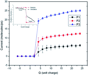 | ||
| Fig. 2 Charge dependence of the water flux in carbon nanotubes for different water pressure gradients. The pressure gradients of P1, P2 and P3 is 2 × 10⁷, 4 × 10⁷ and 1 × 10⁸ Pa Å−1 respectively. | ||
From Fig. 2 we can see that this device works well when it is used as a water switch. The Q value is a critical factor which may change the state of the water channel. It is easy to understand why the channel is shut down when Q is negative. Under this condition, the two potassium ions caged in the piston are subject to an upward electric field force, so they may take the piston move to the top of the water channel, and block the water flow. When the Q value is positive and is greater than 4 unit charges, the situation is opposite. The direction of the electric field force exerted on the potassium ions is downward, and the piston moves to the bottom of the T-type CNT, which induce the opening of the water channel. It is a little confusing that the channel is closed when Q is positive but less than 4 unit charges. The reason for this phenomenon is that the van der Waals force exerted by the T-type CNT to the capped CNT is not zero in the vertical direction because of the asymmetric structure of the T-type CNT. The resultant force is upward. When Q is zero, the piston stays at the top of the T-type CNT. Only when the Q value reaches 4 unit charges, the electric field force may overcome the upward van der Waals force, then the piston can move downward and the channel is opened.
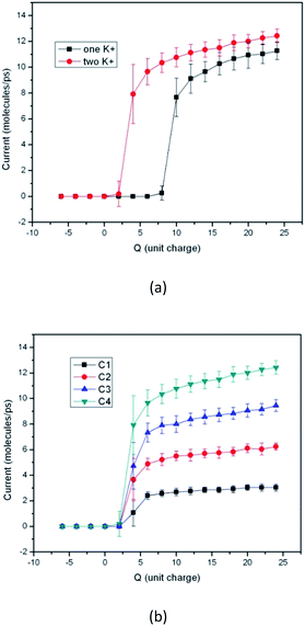
Fig. 3 gives the results when the switch works under other condition. Fig. 3(a) gives the performance comparison of the device when different number of potassium ion is put into the capped CNT. It can be seen that the device may perform as a switch even though only one potassium ion is in the piston. The trends of the two curves are similar, except that the threshold Q value is different. When the number of potassium ion is decreased from 2 to 1, the threshold Q value increases from 4 to 10 unit charges. The result shown in Fig. 3(b) is obtained by using different number of water molecules, provided 10, 20, 30 and 40 water molecules are put into the channel respectively. It shows that the performance of the device is independent of the water concentration. In all the situations the thresholds of the Q value are same.
In order to investigate the dynamic response character of the switch, an alternative outer electric field is created by changing the sign of Q every 1 × 10⁶ steps. Under this alternative electric field, the switch toggles between the open and close state. Fig. 4(a)–(c) are corresponding to the pressure gradient 2 × 10⁷, 4 × 10⁷ and 1 × 10⁸ Pa Å−1 respectively. For almost all situations the switch has high response speed (less than one nanosecond). Although for small Q value, the startup speed is a little slower than the shutdown speed. Only when the pressure gradient is 2 × 10⁷ Pa Å−1 and Q is 4 unit charges the switch occasionally cannot open normally. This means small Q value and small pressure gradient may make the switch not work normally. It should be noted that when the switch state changes from “open” to “close”, the water flow decreases sharply to zero, but when the state changes from “close” to “open”, the situation is different. The water flow is not stable but oscillates up and down. The oscillating amplitude is closely related to the pressure gradient. Larger pressure gradient means smaller oscillation amplitude. With the Q value of 4 unit charges, the oscillation amplitude reaches 80% in Fig. 4(a), but only 20% in Fig. 4(c). This demonstrates that larger flow quantity make the open state more stable. Another factor that influences the oscillating amplitude is the Q value. The open state with larger Q value can be more stable.
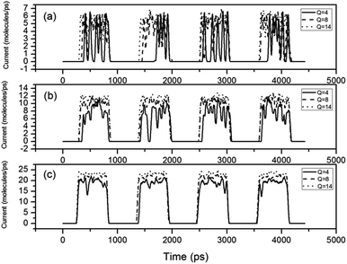 | ||
| Fig. 4 Water currents change with time under different pressure gradients. The pressure gradients are (a) 2 × 10⁷, (b) 4 × 10⁷ and (c) 1 × 10⁸ Pa Å−1, respectively. | ||
We have also recorded the position of the piston during the calculation period. Fig. 5 shows the position of the top of the piston with the pressure gradient of 4 × 10⁷ Pa Å−1. The zero position is the central line of the horizon CNT. It can be seen that when the piston stays at the top of the CNT, its position is almost constant, while when the piston moves to the bottom, its position is not stable. So we can get a conclusion that the instability of the water flow at open state is caused by the instability of the piston position.
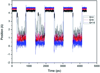 | ||
| Fig. 5 Position (Y-direction) of CNTs piston changes with time, under the pressure gradient of 4 × 10⁷ Pa Å−1. | ||
4. Conclusions
In this research we have proposed a nano-scale water switch, consisting of one T-type CNT and a capped CNT. The capped CNT, with one or two potassium ions in it, may move under the static electric field and plays a role of piston. The results of molecular dynamic simulation show that this device performs well as a water switch. When the piston moves upward, the water flow decreases and finally is blocked. When the piston goes downward, the water channel is open, and water may flow through the CNT smoothly. The stability of the piston position is influenced by the water pressure and the static electric field. High pressure and strong electric field make the piston position move more stably. It is also presented that the switch has nanosecond response speed. Furthermore, the switch can operate stably under 100–1000 atm. This research provides some valuable suggestions for designing and fabricating nano-scale water control devices.Acknowledgements
The authors would like to thank the high performance computing platform of Jinan University and the Siyuan clusters. This study was supported in part by the Natural Science Foundation of Guangdong Province, China (Grant no. 2014A030313367); and the Fundamental Research Funds for the Central Universities, JNU (Grant no. 11614341).Notes and references
- V. P. Sokhan, D. Nicholson and N. Quirke, J. Chem. Phys., 2004, 120, 3855–3863 CrossRef CAS PubMed.
- J. K. Holt, H. G. Park, Y. Wang, M. Stadermann, A. B. Artyukhin, C. P. Grigoropoulos, A. Noy and O. Bakajin, Science, 2006, 312, 1034–1037 CrossRef CAS PubMed.
- J.-L. Wen, D.-Q. Zheng and W.-R. Zhong, RSC Adv., 2015, 5, 99573–99576 RSC.
- M. Elimelech and W. A. Phillip, Science, 2011, 333, 712 CrossRef CAS PubMed.
- Z.-C. Xu, D.-Q. Zheng, B.-Q. Ai and W.-R. Zhong, Sci. Rep., 2016, 6, 23414 CrossRef CAS PubMed.
- S. Meng, W. L. Wang, P. Maragakis and E. Kaxiras, Nano Lett., 2007, 7, 2312 CrossRef CAS PubMed.
- G. Hummer, J. C. Rasaiah and J. P. Noworyta, Nature, 2001, 414, 188–190 CrossRef CAS PubMed.
- J. Su and H. Guo, ACS Nano, 2011, 5, 351–359 CrossRef CAS PubMed.
- K. Ritos, M. K. Borg, N. J. Mottram and J. M. Reese, Philos. Trans. R. Soc., A, 2015, 374, 20150025 CrossRef PubMed.
- K. F. Rinne, S. Gekle, D. J. Bonthuis and R. R. Netz, Nano Lett., 2012, 12, 1780–1783 CrossRef CAS PubMed.
- S. Joseph and N. R. Aluru, Phys. Rev. Lett., 2008, 101, 064502 CrossRef PubMed.
- Z. Xu, C. Wang, N. Sheng, G. Hu, Z. Zhou and H. Fang, J. Chem. Phys., 2016, 144, 014302 CrossRef PubMed.
- A. Kayal and A. Chandra, J. Chem. Phys., 2015, 143, 224708 CrossRef PubMed.
- R. Wan, J. Li, H. Lu and H. Fang, J. Am. Chem. Soc., 2005, 127, 7166–7170 CrossRef CAS PubMed.
- J.-W. Feng, H.-M. Ding and Y.-Q. Ma, J. Chem. Phys., 2014, 141, 094901 CrossRef PubMed.
- J. Liu, G. Shi, P. Guo, J. Yang and H. Fang, Phys. Rev. Lett., 2015, 115, 164502 CrossRef PubMed.
- A. Weidinger, M. Waiblinger, B. Pietzak and T. A. Murphy, Appl. Phys. A, 1998, 66, 287–292 CrossRef CAS.
- K. Lips, M. Waiblinger, B. Pietzak and A. Weidinger, Phys. Status Solidi A, 2000, 177, 81 CrossRef CAS.
- M. Waiblinger, K. Lips, W. Harneit and A. Weidinger, Phys. Rev. B: Condens. Matter Mater. Phys., 2001, 63, 045421 CrossRef.
- B. Xu and X. Chen, Phys. Rev. Lett., 2013, 110, 156103 CrossRef PubMed.
- K. Nomura and S. Okada, Chem. Phys. Lett., 2014, 608, 351–354 CrossRef CAS.
- S. Melchor and J. A. Dobado, J. Chem. Inf. Comput. Sci., 2004, 44, 1639–1646 CrossRef CAS PubMed.
- D. W. Brenner, Phys. Rev. B: Condens. Matter Mater. Phys., 1990, 42, 9458 CrossRef CAS.
- K. Toukan and A. Rahman, Phys. Rev. B: Condens. Matter Mater. Phys., 1985, 31, 2643 CrossRef CAS.
- G. Stan, M. J. Bojan, S. Curtarolo, S. M. Gatica and M. W. Cole, Phys. Rev. B: Condens. Matter Mater. Phys., 2000, 62, 2173 CrossRef CAS.
- W. Zhong, Z. Xu, D. Zheng and B. Ai, Appl. Phys. Lett., 2014, 104, 081914 CrossRef.
- R. E. Tuzun, D. W. Noid, B. G. Sumpter and R. C. Merkle, Nanotechnology, 1996, 7, 241 CrossRef CAS.
Footnote |
| † Electronic supplementary information (ESI) available. See DOI: 10.1039/c7ra00308kk |
| This journal is © The Royal Society of Chemistry 2017 |

