 Open Access Article
La2Sn2O7 enhanced photocatalytic CO2 reduction with H2O by deposition of Au co-catalyst†
Shuang Chen,
Bao Pan,
Longquan Zeng,
Shijian Luo,
Xuxu Wang and
Wenyue Su *
*
State Key Laboratory of Photocatalysis on Energy and Environment, Fuzhou University, Fuzhou 350002, P. R. China. E-mail: suweny@fzu.edu.cn; Fax: +86-591-83779105; Tel: +86-591-83779105
First published on 2nd March 2017
Abstract
La2Sn2O7 (LSO) micro/nanospheres, synthesized by a hydrothermal method, exhibited photocatalytic performance for CO2 reduction. The evolution rate of the main reduction products (CH4 and CO) was 0.20 and 0.10 μmol h−1, respectively. Loading of Au co-catalyst over La2Sn2O7 efficiently enhanced the photocatalytic activity of CO2 reduction. The highest photocatalytic efficiency was obtained over 1 wt% Au/La2Sn2O7 with an apparent quantum yield (AQY) of 2.54%. Characterization techniques including SEM, TEM, XRD, XPS, DRS, PL, and electrochemical analysis were applied and the physicochemical properties of La2Sn2O7 and Au/La2Sn2O7 samples are discussed. A possible mechanism of photocatalytic CO2 reduction over Au/La2Sn2O7 is proposed.
1. Introduction
Because of the growing consumption of fossil fuels, atmospheric levels of carbon dioxide are greatly increasing thus causing tremendous concerns about ensuing effects on the global climate and future energy supplies. Research activities on the potential conversion of CO2 are thus considerably stimulated.1,2 Photocatalytic transformation of CO2 is one of the most promising routes for the utilization of CO2 because it can reduce CO2 to hydrocarbon fuels, such as CH4 and CH3OH, by solar energy in an environmentally friendly manner. Recently, various materials for photocatalytic CO2-reduction such as La2Ti2O7,3 LaPO4,4–6 TiO2,7–12 C3N4,13–15 ZnO,16 Zn2GeO4,17 TaON,18 BaCeO3,19 CdS20–23 and metal complexes24 have been reported, but with relatively low efficiencies. The synthesis of photocatalysts with high performance for CO2 reduction has been a challenging – yet vital – research topic.Semiconductors with a sufficiently more negative conduction band edge than the reduction potential of CO2, and with superior CO2 adsorption capability, favour photocatalytic CO2 reduction.4 Lanthanum-based materials, due to a highly negative conduction band edge, may be suitable for efficient reduction of CO2 with H2O25 and alkaline lanthanum cations are considered to have efficient CO2 adsorption sites.26 Many lanthanum-based materials have been reported with photocatalytic performance for hydrogen production and photocatalytic CO2 reduction.5,7 La2Sn2O7, as a key member of the lanthanum-based stannate family, possesses tailorable and tunable pyrochlore properties with high possibilities of leading to a wide variety of chemical and physical properties which could be applied as luminescent materials27 and catalysts for different reactions.28,29 Therefore, La2Sn2O7 materials are expected to be promising candidates for CO2-reduction photocatalysts.
In the present study, a La2Sn2O7 sample was prepared by a hydrothermal method and its photocatalytic performance for CO2 reduction with H2O was investigated. Au nanoparticles were deposited on La2Sn2O7 by a NaBH4 reduction method in order to acquire higher photocatalytic CO2 reduction efficiency. Synthesized La2Sn2O7 and Au/La2Sn2O7 samples were characterized by physical and chemical measurements and the effects of Au doping on photocatalytic performance are discussed. A possible reaction mechanism for photocatalysis on the prepared La2Sn2O7 and Au/La2Sn2O7 samples under UV light irradiation is also proposed.
2. Experimental
2.1. Catalyst preparation
La2Sn2O7 was fabricated via a hydrothermal method. In a typical experiment, 2 mmol La(NO3)3·6H2O and 2 mmol Na2SnO3 were dissolved in 40 mL DI water at room temperature with stirring to form a homogeneous solution. Then, Na2SnO3 solution was added into the La(NO3)3 solution drop by drop with vigorous stirring. The resulting suspension was transferred into a 100 mL Teflon-lined stainless steel autoclave and hydrothermally treated at 200 °C for 12 h, and then cooled naturally. The precipitate was collected by centrifugation and washed several times with distilled water before drying at 60 °C to obtain the final product. Au nanoparticles were deposited on the surface of La2Sn2O7 (Au/La2Sn2O7) by a NaBH4 reduction method. The La2Sn2O7 powders were dissolved in 100 mL H2O by ultrasonic dispersion and an appropriate volume of HAuCl4 solution (5 mg Au mL−1) was added. After vigorous stirring for 12 hours, the resulting mixture was reduced with NaBH4 solution (0.1 M), then centrifuged and washed thoroughly with distilled water, and dried at 60 °C for 12 h. The gold contents of the samples were estimated by precursor feeding. The values for the actual Au loading of the synthesized catalysts were obtained by using an inductively coupled plasma mass spectrometer (ICP-MS, OPTIMA 8000), and summarized in Table S1.†2.2. Characterization
Powder X-ray diffraction (XRD) data was collected using a Bruker D8 Advance instrument (Cu Kα1 irradiation, =1.5406 Å). Morphological images of the surfaces and transmission electron micrographs were obtained using a Nova NanoSEM 230 microscope (FEI Corp) and a JEOL JEM 2010F microscope. UV-vis diffuse reflectance spectra (DRS) were measured using a Varian Cary 500 Scan, with BaSO4 as a reference. X-ray photoelectron spectroscopy (XPS) measurements were performed on an ESCALAB 250 photoelectron spectroscope system. Brunauer–Emmett–Teller (BET) specific surface area and CO2 adsorption were recorded using an ASAP2020M apparatus. Electrochemical experiments were performed in a three-electrode cell made of quartz. A Pt plate and Ag/AgCl electrode served as the counter electrode and reference electrode, respectively. The working electrode was made by dip-coating a catalyst slurry (10 mg mL−1 in EtOH) on fluorine-doped tin oxide (FTO) glasses, whose area was set as ca. 0.5 cm × 0.5 cm, and then was air-dried naturally. Electrochemical experiments were determined by a Zennium electrochemical workstation (Zahner Elektrik, Germany). The Mott–Schottky experiments and photocurrent response behaviors were conducted on a Precision PARC workstation. A 0.2 M Na2SO4 aqueous solution was used as the electrolyte for the two experiments. A 300 W Xe lamp (CEL-S500/350) was utilized as the light source for the photocurrent response behavior test. Electrochemical impedance spectroscopy (EIS) experiments were conducted on a CHI660D workstation (CH instrument) in an electrolyte of 0.5 M KCl aqueous solution containing 0.01 M K3[Fe(CN)6]/K4[Fe(CN)6] (1![[thin space (1/6-em)]](https://www.rsc.org/images/entities/char_2009.gif) :
:![[thin space (1/6-em)]](https://www.rsc.org/images/entities/char_2009.gif) 1). Photoluminescence (PL) spectra were carried out on an Edinburgh instrument FLS980 spectrophotometer at ambient conditions.
1). Photoluminescence (PL) spectra were carried out on an Edinburgh instrument FLS980 spectrophotometer at ambient conditions.
2.3. Photocatalytic reactions
Photocatalytic reactions for CO2 reduction were carried out at 1 atm CO2 partial pressure in a 200 mL reactor, with an irradiation quartz reaction cell inside of it. 50 mg photocatalyst was added into the quartz reactor and dispersed in 140 mL H2O. A 125 W high-pressure mercury lamp (GGZ125, Shanghai Yaming Lighting Co, Ltd with a maximum emission at about 365 nm) was used as the light source and the reactor was kept invariably at 20 °C by flowing cooling water during the reaction process. The whole reaction system was first evacuated by a mechanical pump to remove air before irradiation, then CO2 (99.999% purity) was introduced into the reactor for 40 minutes to establish an adsorption–desorption balance and provide the necessary reaction gas. Gas products were detected by GC (Agilent 6890N) and the apparent quantum yield (AQY) was also measured under the same photocatalytic reaction conditions. The incident light intensity of a high pressure mercury lamp was measured by Spectri Light ILT950. The total number of incident photons was collected by a calibrated silicon photodiode.The apparent quantum yield (AQY) was calculated from the following equations:
3. Results and discussion
3.1. Characterization of La2Sn2O7 and Au/La2Sn2O7
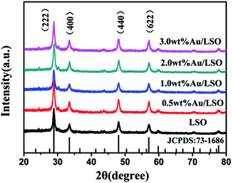
XRD patterns of the La2Sn2O7 and Au/La2Sn2O7 samples are shown in Fig. 1. The four characteristic peaks located at 28.8°, 33.4°, 48.0°, and 57.0° are indexed to the (222), (400), (440), and (622) diffraction planes of cubic crystalline La2Sn2O7 (JCPDS: 73-1686), respectively. The average crystal size of the La2Sn2O7 sample is estimated to be about 14.5 nm from the (222) peak at around 28.8° by using the Scherrer equation. Diffraction peaks of the Au/La2Sn2O7 sample ascribe only to the cubic phase of La2Sn2O7, and no diffraction peaks for Au were observed. This is due to a lower amount of metal loading and homogenous dispersion of Au on the La2Sn2O7.Morphology and sizes of the samples were characterized by SEM and TEM. The La2Sn2O7 sample shows micro/nanospheres with diameters that varied from 300 to 500 nm, assembled by densely arranged nanoparticles (Fig. 2a). The TEM of the 1 wt% Au/La2Sn2O7 sample indicates few Au NPs dispersed on the La2Sn2O7 surface (Fig. 2b). The HRTEM image of the 1 wt% Au/La2Sn2O7 sample (Fig. 2c) shows a lattice spacing of ca. 0.234 nm, corresponding to the (111) planes of Au NPs,30,31 and the size of the Au particle is about 5–7 nm. Meanwhile, the lattice spacing of the La2Sn2O7 structure is ca. 0.309 nm, corresponding to the (222) plane of cubic La2Sn2O7. Furthermore, the obtained EDX pattern corresponding to Fig. 2d shows the presence of La, Sn, O, Au, and Cu elements (Cu peaks arise from TEM grid), and the obtained EDX-mapping (Fig. S1†) shows uniform distribution of the elements.
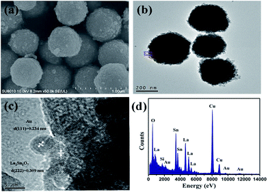 | ||
| Fig. 2 (a) SEM image of the La2Sn2O7 sample; (b) TEM image; (c) HRTEM image; (d) EDX pattern of the 1 wt% Au/La2Sn2O7 sample. | ||
An X-ray photoelectron spectroscopy (XPS) survey spectrum of the prepared 1 wt% Au/La2Sn2O7 sample (Fig. S2†) indicates the presence of La, Sn, O, and Au. No other element signal is found except for a C signal (attributed to adventitious carbon), in accord with the results of EDX (Fig. 2d). In the high resolution XPS spectrum of Au 4f (Fig. 3a), two main peaks located at 82.7 and 86.4 eV correspond to Au0 4f7/2 and Au0 4f5/2.32 And the Au0 4f7/2 negative binding energy shift of 1.4 eV, compared with that of bulk metallic Au0 (84.1 eV), indicates strong interactions between Au and La2Sn2O7.33 With regard to La 3d (Fig. 3b), the binding energies of La 3d5/2 and La 3d3/2 peaks are present at 836.1 and 853.2 eV with the shake-up peaks located at 840.2 and 857.3 eV, respectively, consistent with the reported results of La3+ in a La(III) oxidation state.34 The Sn 3d XPS spectra (Fig. 3c) show two main peaks at 486.2 eV (Sn 3d5/2) and 494.7 eV (Sn 3d3/2) with the shake-up peaks located at 488.3 and 496.7 eV,35 which may be assigned to the characteristic of Sn4+. As for O 1s XPS spectra (Fig. 3d), the O 1s signal could be fit into two peaks, and the peaks located at 528.7 and 531.2 eV are ascribed to the crystal lattice oxygen and surface hydroxyl, respectively.36
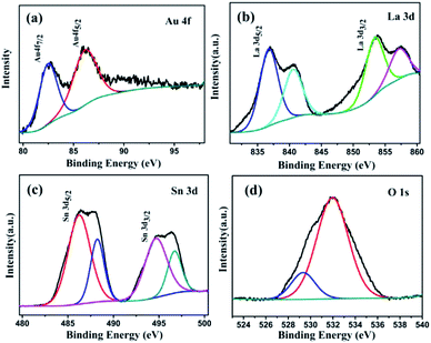 | ||
| Fig. 3 XPS spectra of the 1 wt% Au/La2Sn2O7 sample: (a) Au element; (b) La element; (c) Sn element; and (d) O element. | ||
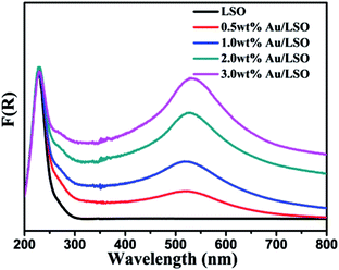
The UV-vis diffused reflection spectra of the samples are shown in Fig. 4. Onset of the absorption edge for the La2Sn2O7 is at about 315 nm. The corresponding bandgap energy (Eg) is estimated to be 3.93 eV, as determined by equation E = 1240/λ. Compared to bare La2Sn2O7 materials, the absorption edge of Au/La2Sn2O7 samples does not change, suggesting that Au is only loaded on the surface of La2Sn2O7 rather than being incorporated into the lattice of La2Sn2O7.37 Meanwhile, an intense absorption band is centered at 531 nm, which could be assigned to the SPR of the Au NPs.38 It can be seen that Au loading enhances the light absorption of La2Sn2O7 samples, and the absorption intensity heightens along with increased Au doping amounts.
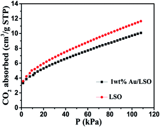
The BET surface area (SBET) of the prepared samples was investigated by N2 adsorption–desorption measurements. The SBET of the as-prepared La2Sn2O7 and 1 wt% Au/La2Sn2O7 were measured to be 75.6 and 70.6 m2 g−1 (Fig. S3†), respectively. The wide pore size distribution curves (Fig. S4†) indicate stacking among the small La2Sn2O7 nanoparticles. Meanwhile, CO2 adsorption over the samples was also measured and results are shown in Fig. 5. The CO2 adsorption amounts of the La2Sn2O7 and 1 wt% Au/La2Sn2O7 samples are 11.65 and 10.07 cm3 g−1 (Fig. 5), respectively. 1 wt% Au/La2Sn2O7 shows a lower CO2 adsorption capability compared to La2Sn2O7, which may be due to some surface CO2 adsorption sites, such as La species over La2Sn2O7, that are covered with deposited Au nanoparticles.39
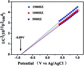
As shown in Fig. 6, the flat-band potential of La2Sn2O7 determined from Mott–Schottky plots is ca. −0.89 V vs. Ag/AgCl at pH 7 (equivalent to −0.69 V vs. NHE at pH 7). The positive slopes of these plots suggest that La2Sn2O7 is an n-type semiconductor.40 With regard to the n-type semiconductor, the conduction band lies very close to the flat-band potentials.41 Therefore, the conduction band (ECB) of La2Sn2O7 is −0.79 V vs. NHE at pH 7, which is more negative than the redox potential of CO2/CO (−0.53 V vs. NHE), CO2/CH4 (−0.24 V vs. NHE), and H2O/H2 (−0.41 V vs. NHE). So, it is thermodynamically possible that the photogenerated electrons in the prepared La2Sn2O7 reduce CO2 with H2O to CO, CH4, and H2.
3.2. Photocatalytic activity and stability
Photocatalytic CO2 reduction activities of the samples were investigated under mild conditions without any sacrificial reagents. As shown in Fig. 7a, the samples exhibited photocatalytic performance for CO2 reduction with H2O, and CH4, CO, and H2 are the main reduction products; other products such as CH3OH, HCHO, and HCOOH were not detected during the reaction. The output products of CH4, CO, and H2, over bare La2Sn2O7 were 0.60, 0.31, and 6.90 μmol after 3 h irradiation, corresponding to the evolution rates of 0.20, 0.10, and 2.30 μmol h−1, respectively, with an apparent quantum yield (AQY) of 0.89%, which is superior to the P25 sample with a AQY of 0.68% (Table S2†). After loading Au, the samples exhibited better photocatalytic CO2 reduction activities. The evolution rate of the main products increased with addition of Au. When the loading amount of Au reached 1.0 wt%, the evolution rate of CH4, CO, and H2 increased to the max of 0.43, 0.37, and 6.98 μmol h−1, respectively (Fig. 7b), which was 2.2, 3.7, and 3.0 times as high as that of bare La2Sn2O7. The generation of H2, CH4, and CO over 1.0 wt% Au/La2Sn2O7 increased almost linearly with irradiation time (Fig. 7b), and their outputs are 2.05, 1.74, and 33.08 μmol after 5 h irradiation, respectively, with an apparent quantum yield (AQY) (2.54%) enhanced by 3 times more than the La2Sn2O7 sample.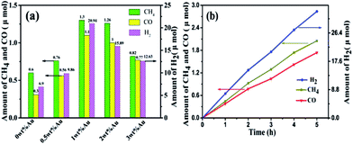 | ||
| Fig. 7 (a) The output of CH4, CO, and H2 over La2Sn2O7 and Au/La2Sn2O7 samples under irradiation for 3 h; (b) CH4, CO, and H2 formed as a function of irradiation time over 1 wt% Au/La2Sn2O7 samples. | ||
The amount of O2 formed was also measured to determine charge balance during the photocatalytic reaction. After a 5 h photocatalytic reaction over the 1.0 wt% Au/La2Sn2O7 sample, the amount of O2 was 21.08 μmol. Supposing that the oxidation of H2O to O2 is the only reaction to expend the photogenerated holes, and the photogenerated electrons are used to form CH4, CO, and H2, then the stoichiometric molar ratio of O2/(4CH4 + H2 + CO) should be 0.5. The molar ratio of O2/(4CH4 + H2 + CO) calculated from our results is 0.49, which is reasonably close to the stoichiometric ratio.
Stability is very important for practical photocatalytic systems; thus cyclic testing of the photocatalytic CO2 reduction activities was performed to investigate stability. During the 4 times repeated reaction cycles of a 1 wt% Au/La2Sn2O7 sample (Fig. S5†), there was no distinct decrease in H2, CH4, and CO evolution rates, thus demonstrating that the 1 wt% Au/La2Sn2O7 sample shows considerable photostability.
Control experiments were also carried out. No product was detected in the reaction system in the dark or without catalyst, indicating that the CO2 reduction requires presence of a photocatalyst. Only H2 was detected when CO2 was replaced by high purity N2 in the reaction system. This result suggests that the formed reduced products originated from CO2 and not from other sources of contamination.
3.3. Photocatalytic mechanism
Transient photocurrent responses of the La2Sn2O7 and 1 wt% Au/La2Sn2O7 samples were measured under intermittent UV-vis illumination. As shown in Fig. 8a, the transient photocurrent of a 1 wt% Au/La2Sn2O7 sample was much higher than that of the bare La2Sn2O7, indicating a more efficient separation and longer lifetime of photogenerated charge carriers with the loading of Au.42 It has been proven that a smaller arc radius in a Nyquist plot implies a more effective charge separation of electron–hole pairs and a faster interfacial charge transfer.43,44 The impedance arc of 1 wt% Au/La2Sn2O7 is much smaller than that of La2Sn2O7 (Fig. 8b), corresponding to its higher speed of charge separation of electron–hole pairs and interfacial charge transfer, which agrees well with their photocatalytic performances as discussed above. Meanwhile, photoluminescence spectra of the La2Sn2O7 and 1 wt% Au/La2Sn2O7 samples with an excitation wavelength of 310 nm are shown in Fig. 9. A strong PL emission spectrum centered around 410 nm is observed over the La2Sn2O7, which comes from a trap-state emission, originating from the anion (O2−) or cation (La3+ and Sn4+) vacancy defects, and other crystallographic defects.45 After loading Au on La2Sn2O7, the emission intensity remarkably decreases, indicating enhancement of the separation and transfer of photogenerated electrons and holes. This result also is in accordance with the photocurrent performance. All the observations above highlight the function of the Au co-catalyst for enhancing charge transfer, leading to a higher photocatalytic efficiency.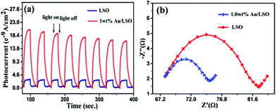 | ||
| Fig. 8 (a) Transient photocurrent response; (b) Nyquist plots of La2Sn2O7 and 1 wt% Au/La2Sn2O7 samples. | ||
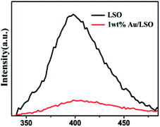 | ||
| Fig. 9 Photoluminescence (PL) spectra of La2Sn2O7 and 1 wt% Au/La2Sn2O7 samples collected at the excitation wavelength of 310 nm. | ||
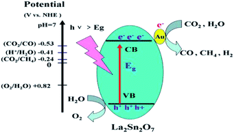
The mechanism for CO2 reduction with H2O over Au/La2Sn2O7 is proposed as shown in Fig. 10. When light with photon energy higher or equal to the band gap of La2Sn2O7 is incident on the sample, then electrons and holes are generated in the CB and VB, respectively. Photogenerated electrons on the CB are transferred to the absorbed CO2 and H+ to produce CH4, CO or H2 on the surface of La2Sn2O7. Simultaneously, holes on the VB edge of La2Sn2O7 are positive enough to oxidize water to form O2. The deposited Au acts as a co-catalyst which facilitates transfer of photoexcited electrons and prevents the recombination of photoexcited electrons and holes.
4. Conclusion
La2Sn2O7 micro/nanospheres were successfully synthesized by a facile hydrothermal method and Au nanoparticles were deposited on La2Sn2O7 via H2AuCl6 impregnation followed by NaBH4 reduction. The prepared La2Sn2O7 sample showed photocatalytic CO2 reduction activities and CH4, CO, and H2 were the main reduction products. Deposition of an Au co-catalyst significantly improved photocatalytic performance. The highest evolution rates of CH4, CO, and H2 were observed over 1.0 wt% Au/La2Sn2O7 samples with 0.43, 0.37, and 6.98 μmol h−1, respectively. The apparent quantum yield (AQY) was 2.54%, which was enhanced by 3 times in contrast to bare La2Sn2O7. An Au co-catalyst plays an excellent role as an electron transfer mediator. Our results indicate promising application of the La2Sn2O7 photocatalyst for CO2 reduction. Moreover, Au nanoparticles could be superior candidates for a co-catalyst to enhance CO2 reduction activities.Acknowledgements
This work was financially supported by the NSFC (Grants No. U1305242, 21373050), the National Key Basic Research Program of China (973 Program: 2013CB632405, 2014CB239303, 2014CB260410, 2014BAC13B03).Notes and references
- L. Yuan and Y. J. Xu, Appl. Surf. Sci., 2015, 342, 154–167 CrossRef CAS.
- E. V. Kondratenko, G. Mul, J. Baltrusaitis, G. O. Larrazabal and J. Perez-Ramirez, Energy Environ. Sci., 2013, 6, 3112–3135 CAS.
- Z. Wang, K. Teramura, S. Hosokawa and T. Tanaka, Appl. Catal., B, 2015, 163, 241–247 CrossRef CAS.
- B. Pan, S. J. Luo, W. Y. Su and X. X. Wang, Appl. Catal., B, 2015, 168, 458–464 CrossRef.
- B. Pan, Y. G. Zhou, W. Y. Su and X. X. Wang, Nano Res., 2017, 10, 534–545 CrossRef CAS.
- B. Pan, Y. G. Zhou, W. Y. Su and X. X. Wang, RSC Adv., 2016, 6, 34744–34747 RSC.
- C. Xu, X. P. He, C. Wang, X. Chen, R. S. Yuan and W. X. Dai, RSC Adv., 2016, 6, 84068–84073 RSC.
- A. Sarkar, E. Gracia-Espino, T. Wagberg, A. Shchukarev, M. Mohl, A. R. Rautio, O. Pitkanen, T. Sharifi, K. Kordas and J. P. Mikkola, Nano Res., 2016, 9, 1956–1968 CrossRef CAS.
- M. Wang, Q. T. Han, Y. Zhou, P. Li, W. G. Tu, L. Q. Tang and Z. G. Zou, RSC Adv., 2016, 6, 81510–81516 RSC.
- M. S. Akple, J. X. Low, S. W. Liu, B. Cheng, J. G. Yu and W. K. Ho, J. CO2 Util., 2016, 16, 442–449 CrossRef CAS.
- M. Tahir, B. Tahir and N. A. S. Amin, Appl. Surf. Sci., 2015, 356, 1289–1299 CrossRef CAS.
- O. Ola and M. M. Maroto-Valer, J. Photochem. Photobiol., C, 2015, 24, 16–42 CrossRef CAS.
- J. N. Qin, S. B. Wang, H. Ren, Y. D. Hou and X. C. Wang, Appl. Catal., B, 2015, 179, 1–8 CrossRef CAS.
- W. J. Ong, L. K. Putri, L. L. Tan, S. P. Chai and S. T. Yong, Appl. Catal., B, 2016, 180, 530–543 CrossRef CAS.
- W. L. Yu, D. F. Xu and T. Y. Peng, J. Mater. Chem. A, 2015, 3, 19936–19947 CAS.
- T. Wang, L. Shi, J. Tang, V. Malgras, S. Asahin]a, G. G. Liu, H. B. Zhang, X. G. Meng, K. Chang, J. P. He, O. Terasaki, Y. Yamauchi and J. H. Ye, Nanoscale, 2016, 8, 6712–6720 RSC.
- Q. Liu, Y. Zhou, Z. P. Tian, X. Y. Chen, J. Gao and Z. G. Zou, J. Mater. Chem., 2012, 22, 2033–2038 RSC.
- Q. T. Han, Y. Zhou, L. Q. Tang, P. Li, W. G. Tu, L. Li, H. J. Lia and Z. G. Zou, RSC Adv., 2016, 6, 90792–90796 RSC.
- J. Wang, C. X. Huang, X. L. Chen, H. T. Zhang, Z. S. Li and Z. G. Zou, Appl. Surf. Sci., 2015, 358, 463–467 CrossRef CAS.
- S. B. Wang and X. C. Wang, Appl. Catal., B, 2015, 162, 494–500 CrossRef CAS.
- J. G. Yu, J. Jin, B. Cheng and M. Jaroniec, J. Mater. Chem. A, 2014, 2, 3407–3416 CAS.
- J. Jin, J. G. Yu, D. P. Guo, C. Cui and W. K. Ho, Small, 2015, 11, 5262–5271 CrossRef CAS PubMed.
- S. Ijaz, M. F. Ehsan, M. N. Ashiq, N. Karamat and T. He, Appl. Surf. Sci., 2016, 390, 550–559 CrossRef CAS.
- Y. Yamazaki, H. Takeda and O. Ishitani, J. Photochem. Photobiol., C, 2015, 25, 106–137 CrossRef CAS.
- Y. Xu and M. A. A. Schoonen, Am. Mineral., 2000, 85, 543–556 CrossRef CAS.
- S. P. Wang, S. L. Yan, X. B. Ma and J. L. Gong, Energy Environ. Sci., 2011, 4, 3805–3819 CAS.
- J. Yang, Y. Su, H. Li, X. Liu and Z. Chen, J. Alloys Compd., 2011, 509, 8008–8012 CrossRef CAS.
- S. Park, Solid State Ionics, 2004, 175, 625–629 CrossRef CAS.
- J. Zeng, H. Wang, Y. C. Zhang, M. K. Zhu and H. Yan, J. Phys. Chem. C, 2007, 111, 11879–11887 CAS.
- Z. Y. Zhang, Z. Wang, S. W. Cao and C. Xue, J. Phys. Chem. C, 2013, 117, 25939–25947 CAS.
- B. J. Borah, S. J. Borah, K. Saikia and D. K. Dutta, Catal. Sci. Technol., 2014, 4, 4001–4009 CAS.
- W. B. Hou, W. H. Hung, P. Pavaskar, A. Goeppert, M. Aykol and S. B. Cronin, ACS Catal., 2011, 1, 929–936 CrossRef CAS.
- F. L. Wang, Y. J. Jiang, D. J. Lawes, G. E. Ball, C. F. Zhou, Z. W. Liu and R. Amal, ACS Catal., 2015, 5, 3924–3931 CrossRef CAS.
- D. Barreca, A. Gasparotto, C. Maragno, E. Tondello, E. Bontempi, L. E. Depero and C. Sada, Chem. Vap. Deposition, 2005, 11, 426–432 CrossRef CAS.
- P. G. Harrison, N. C. Lloyd, W. Daniell, I. K. Ball, C. Bailey and W. Azelee, Chem. Mater., 2000, 12, 3113–3122 CrossRef CAS.
- Q. H. Xie, Y. Wang, B. Pan, H. M. Wang, W. Y. Su and X. X. Wang, Catal. Commun., 2012, 27, 21–25 CrossRef CAS.
- D. W. Li, S. X. Ouyang, H. Xu, D. Lu, M. Zhao, X. L. Zhang and J. H. Ye, Chem. Commun., 2016, 52, 5989–5992 RSC.
- J. Zhang, X. Jin, P. I. Morales-Guzman, X. Yu, H. Liu, H. Zhang, L. Razzari and J. P. Claverie, ACS Nano, 2016, 10, 4496–4503 CrossRef CAS PubMed.
- J. G. Yu, K. Wang, W. Xiao and B. Cheng, Phys. Chem. Chem. Phys., 2014, 16, 11492–11501 RSC.
- V. Spagnol, E. Sutter, C. Debiemme-Chouvy, H. Cachet and B. Baroux, Electrochim. Acta, 2009, 54, 1228–1232 CrossRef CAS.
- A. Ishikawa, T. Takata, J. N. Kondo, M. Hara, H. Kobayashi and K. Domen, J. Am. Chem. Soc., 2002, 124, 13547–13553 CrossRef CAS PubMed.
- Y. Wang, H. B. Fang, Y. Z. Zheng, R. Q. Ye, X. Tao and J. F. Chen, Nanoscale, 2015, 7, 19118–19128 RSC.
- D. T. You, B. Pan, F. Jiang, Y. G. Zhou and W. Y. Su, Appl. Surf. Sci., 2016, 363, 154–160 CrossRef CAS.
- M. Zeng, X. Zeng, X. G. Peng, Z. Zhu, J. J. Liao, K. Liu, G. Z. Wang and S. W. Lin, Appl. Surf. Sci., 2016, 388, 352–358 CrossRef CAS.
- S. A. Ansari, M. M. Khan, S. Kalathil, A. Nisar, J. Lee and M. H. Cho, Nanoscale, 2013, 5, 9238–9246 RSC.
Footnote |
| † Electronic supplementary information (ESI) available: XPS survey spectrum of the 1 wt% Au/La2Sn2O7 sample; N2 adsorption/desorption isotherms (77 K) of La2Sn2O7 and 1 wt% Au/La2Sn2O7 samples; the stability test of 1 wt% Au/La2Sn2O7 photocatalyst for CH4, CO, H2 evolution rate in four repeats of reaction. See DOI: 10.1039/c7ra00765e |
| This journal is © The Royal Society of Chemistry 2017 |


