 Open Access Article
Creative Commons Attribution 3.0 Unported Licence
Peptide-templated synthesis of branched MnO2 nanowires with improved electrochemical performances†
Mingxuan Dua,
Yong Bua,
Yan Zhoub,
Yurong Zhaoa,
Shengjie Wang*a and
Hai Xu *a
*a
aState Key Laboratory of Heavy Oil Processing and Center for Bioengineering and Biotechnology, China University of Petroleum (East China), No. 66 Changjiang West Road, Qingdao 266580, China. E-mail: sjwang@upc.edu.cn; xuh@upc.edu.cn; Tel: +86-532-86981569
bCollege of Science, China University of Petroleum (East China), No. 66 Changjiang West Road, Qingdao 266580, China
First published on 23rd February 2017
Abstract
Although many nanomaterials have been prepared in vitro by mimicking biomineralization, the biomimetic synthesis of hybrids with both well-ordered nanostructures and specific functions is still in its infancy. A short designed peptide amphiphile I3K can form uniform and stable nanofibers in aqueous solution, with a surface enriched in cationic lysine residue. In the present study, we have demonstrated that the peptide nanofibers could direct the synthesis of MnO2 nanowires under mild conditions. By varying the concentration of manganese precursors (KMnO4 and Mn(NO3)2), uniform branched MnO2/peptide hybrid nanowires with high porosity and a large specific surface area were obtained. The well-defined MnO2 hybrid nanowires showed significantly improved electrochemical supercapacitive properties relative to compact MnO2 nanowires and urchin-like MnO2 spheres. Their specific capacitance could attain a higher value of 421 F g−1 and retained about 93% of the initial capacitance after 2500 cycles at a scan rate of 5 mV s−1, and remained little changed during the process of progressively varying the current density. Furthermore, the electrode prepared from the uniform MnO2 hybrid nanowires showed an excellent reversibility and a reasonably high-rate capability during the charge/discharge process. Such a study provides a new methodology to prepare functional MnO2 nanostructures under mild conditions that can be used in electrochemical energy storage.
Introduction
Supercapacitors have attracted great attention as electro-chemical energy storage devices and exhibited potential applications in hybrid electric vehicles, sensors-actuators, uninterruptable power suppliers, and energy-harvesting systems because of their high power density, rapid charge/discharge rate, temperature stability and long cycling life.1 According to their different charge-storage mechanisms, supercapacitors can be classified into two groups, i.e., double-layer capacitors and pseudo-capacitors.1,2 Compared with the double-layer capacitor in which charge storage merely occurs on the electrode surface, the pseudo-capacitor has higher specific capacitance due to the electrochemical transformation both in the bulk phase and on the surface of electrodes. Pseudo-capacitors that use conducting polymers3–5 or transition metal oxides6–9 as electrode materials rely on redox reactions between these electroactive materials and ions in electrolytes. Metal oxides, such as MnO2, NiO, RuO2, and V2O5 are of particular interest due to their high energy density, multiple and variable oxidation state, and excellent stability during the faradaic reaction.2,6–9 Among them, MnO2 has exhibited many advantages such as high theoretical specific capacitance, low cost and toxicity, nature abundance, and easy preparation, and as a result, it has been widely exploited as one of the most promising electrode materials for pseudo-capacitors.1,2However, the poor electric conductivity and the low accessible surface areas of thick MnO2 often limit the specific capacitance of conventional MnO2 electrodes of only 150–250 F g−1, which is far from the theoretical value of ∼1370 F g−1.2,10–12 Correspondingly, there are currently two strategies to improve the electrochemical capacitance properties of MnO2.2 One is to increase the electrical conductivity of MnO2 electrodes by incorporation of other metal or carbon materials. The other one is to increase the specific surface area and regulate the pore size distribution of MnO2. It is well-known that nanostructured materials usually have high specific surface areas. Thus, different manganese oxide nanostructures such as nanoparticles, nanorods, nanowires, nanoplates, and nanoflowers have been synthesized and their electrochemical capacitance performances were found to be close correlated to the morphologies, surface areas, and pore sizes and distributions.13–16
In order to obtain MnO2 nanomaterials, many methods such as sol–gel transition, hydrothermal synthesis, electrochemical deposition, and template-assisted anodic electrodeposition have been exploited.13–20 To further increase their specific surface areas and simultaneously to avoid the use of special equipment and harsh conditions during synthesis, however, there are still urgent demands for new synthetic strategies that work under mild conditions. Inspired by biomineralization and biomimetic synthesis of well-defined nanostructures,21,22 we here constructed novel MnO2 nanostructures under mild conditions by taking advantage of peptide self-assembly. The used peptide I3K is a designed short amphiphile, three consecutive Ile residues constituting the hydrophobic tail and one positively charged Lys acting as the hydrophilic head (Fig. S1a†).23,24 In aqueous solutions, the peptide can readily self-assemble into uniform and stable nanofibers, and because their surface is enriched in cationic lysine residues, silica nanotubes have been successfully templated.23,25,26 In this case, the I3K nanofibers were found to direct the deposition of MnO2 that arose from the comproportionation reaction between KMnO4 and Mn(NO3)2 in neutral water at room temperature, resulting in the formation of MnO2 nanowires. The templating ability of the peptide nanofibers arose from their surface lysine residues and by varying the concentrations of manganese precursors, MnO2 nanowires with different morphologies could be obtained. The uniform branched MnO2 nanowires had a porous structure with a high specific surface area up to 275 m2 g−1, and importantly, they showed significantly improved electrochemical properties, relative to compact MnO2 nanowires and the urchin-like MnO2 nanospheres formed in the absence of peptide. Such a study provides a simple biomimetic method to obtain MnO2 electrode nanomaterials with excellent electrochemical performances.
Materials and methods
Materials
The peptide I3K was synthesized on a CEM Liberty microwave synthesizer according to Fmoc solid-phase chemistry. The use of Rink amide MBHA resin made its C-terminus amidation while its N-terminus was capped with acetic anhydride before cleavage from the resin. The detailed synthesis and purification procedures have been given in our previous publications.23,24 All the materials used for peptide synthesis were purchased from GL Biochem Ltd (Shanghai, China). KMnO4, Mn(NO3)2, and other reagents were obtained from Sigma-Aldrich and used as received. All water used was obtained from a Millipore water purification system with a minimum resistivity of 18.2 MΩ cm.Peptide self-assembly
I3K showed high solubility in aqueous solutions. After dissolving the peptide in ultrapure water to obtain a clear peptide solution of 4 mM, the solution pH was slightly adjusted to 7.0 using dilute NaOH solution. The peptide solution was kept at room temperature for at least one week before instrumental characterizations and use in mineralization.Preparation of MnO2 nanomaterials
MnO2 was synthesized via the redox reaction between KMnO4 and Mn(NO3)2 in the presence and absence of I3K assemblies. By varying the concentrations of KMnO4 and Mn(NO3)2, different MnO2 nanomaterials were obtained. Taking the synthesis of MP-5 as an example (as indicated in Table 1), 1 mL of the aged I3K solution (4 mM) was mixed with 2.8 mL of ultrapure water, 0.2 mL of 0.1 M KMnO4 aqueous solution, and 0.01 mL of 4 M Mn(NO3)2 aqueous solution, and the final concentration of I3K, KMnO4, and Mn(NO3)2 in the mixture was 1, 5, and 10 mM, respectively. After mixing, brown precipitates were immediately observed, indicating that the reaction was fast. In spite of this feature, the mixture was kept for 24 hours at room temperature to ensure a complete reaction. To remove residual precursors, the above reaction solution was centrifuged at 10![[thin space (1/6-em)]](https://www.rsc.org/images/entities/char_2009.gif) 000 rpm for 10 min, and the precipitate was washed alternately with water and ethanol for three times, followed by freeze-drying overnight. Finally, loose powders of MnO2/peptide hybrid were collected for subsequent characterizations.
000 rpm for 10 min, and the precipitate was washed alternately with water and ethanol for three times, followed by freeze-drying overnight. Finally, loose powders of MnO2/peptide hybrid were collected for subsequent characterizations.
| Name of MnO2 | Concentration (mM) | Morphology | Specific capacitancea (F g−1) | ||
|---|---|---|---|---|---|
| I3K | KMnO4 | Mn(NO3)2 | |||
| a The specific capacitance of MnO2 nanomaterials was calculated from their CV curves at 5 mV s−1, according to the eqn (1). | |||||
| MP-0 | 0 | 5 | 10 | Urchin-like sphere | 194 |
| MP-1 | 1 | 0.1 | 0.2 | Thin and compact nanowire | 124 |
| MP-2 | 1 | 0.2 | 0.4 | Thin and compact nanowire | 139 |
| MP-3 | 1 | 1 | 2 | Thin and compact nanowire | 163 |
| MP-4 | 1 | 2 | 4 | Rough nanowire | 194 |
| MP-5 | 1 | 5 | 10 | Uniform branched nanowire | 421 |
| MP-6 | 1 | 10 | 20 | Branched nanowire (main), urchin-like sphere | 313 |
| MP-7 | 1 | 20 | 40 | Urchin-like sphere (main), branched nanowire | 226 |
Preparation of MnO2 electrodes
The working electrodes were prepared using Ni foam as a current collector (1.0 × 1.0 cm2). The Ni foam was first cleaned successively with ethanol and ultra-pure water to remove residual organics. Then, nanostructured MnO2, acetylene black, and polytetrafluoroethylene were well mixed in ethanol at a mass ratio of 80![[thin space (1/6-em)]](https://www.rsc.org/images/entities/char_2009.gif) :
:![[thin space (1/6-em)]](https://www.rsc.org/images/entities/char_2009.gif) 15
15![[thin space (1/6-em)]](https://www.rsc.org/images/entities/char_2009.gif) :
:![[thin space (1/6-em)]](https://www.rsc.org/images/entities/char_2009.gif) 5 and dried under vacuum at 60 °C for 12 h. After loading the mixed powder onto the Ni foam, the electrode was obtained by pressing the foam under a pressure of 10 MPa.
5 and dried under vacuum at 60 °C for 12 h. After loading the mixed powder onto the Ni foam, the electrode was obtained by pressing the foam under a pressure of 10 MPa.
Instrumental characterizations
Results and discussion
Preparation of branched MnO2 nanowires
As demonstrated previously, I3K nanofibers could template the formation of long silica nanotubes.23,25 The underlying mechanism was related to the lysine residues distributed on the I3K nanofibers' surface and there was an electrostatic attraction between silica intermediates and the surface lysine residues at around neutral pH. By taking advantage of this nanostructured peptide template with a well-defined surface chemistry, we here realized the template synthesis of MnO2 nanomaterials with ordered architectures under mild conditions.Manganese oxide (MnO2) was prepared via the comproportionation reaction between KMnO4 and Mn(NO3)2 in neutral water at room temperature, which is as the following:
| 2MnO4− + 3Mn2+ + 2H2O → 5MnO2 + 4H+ |
In our experiment, the molar ratio of KMnO4 and Mn(NO3)2 was set as 1![[thin space (1/6-em)]](https://www.rsc.org/images/entities/char_2009.gif) :
:![[thin space (1/6-em)]](https://www.rsc.org/images/entities/char_2009.gif) 2, which was slightly lower than their stoichiometric ratio (2
2, which was slightly lower than their stoichiometric ratio (2![[thin space (1/6-em)]](https://www.rsc.org/images/entities/char_2009.gif) :
:![[thin space (1/6-em)]](https://www.rsc.org/images/entities/char_2009.gif) 3), thus allowing the powerful oxidizing agent (KMnO4) to react completely. In the absence of peptide, the collected brown precipitates showed an urchin-like morphology with diameters mostly ranging from 140 to 260 nm (Fig. S2a in ESI†), and it can be seen from a HR-TEM micrograph that the urchin-like structure was assembled from many thin MnO2 nanoflakes (Fig. S2b†).
3), thus allowing the powerful oxidizing agent (KMnO4) to react completely. In the absence of peptide, the collected brown precipitates showed an urchin-like morphology with diameters mostly ranging from 140 to 260 nm (Fig. S2a in ESI†), and it can be seen from a HR-TEM micrograph that the urchin-like structure was assembled from many thin MnO2 nanoflakes (Fig. S2b†).
I3K self-assembled into long nanofibers with diameters of 10.5 ± 3 nm (Fig. S1b†). In the presence of I3K, we also observed brown precipitates immediately after mixing the aged peptide solution with KMnO4 and Mn(NO3)2. After 24 h, however, the collected precipitates showed complete different morphologies from that formed in the absence of peptide. As shown in Fig. 1 and Table 1, we observed the deposition of MnO2 along the peptide nanofibers, resulting in the formation of fiber-like precipitates with a high aspect ratio. Such a peptide-templated synthesis was first verified by FTIR analysis, in which the characteristic bands of both amide and manganese oxide were observed from the collected fiber-like precipitates (Fig. S3†). With increasing the concentration of manganese precursors whilst keeping their molar ratio being constant (KMnO4![[thin space (1/6-em)]](https://www.rsc.org/images/entities/char_2009.gif) :
:![[thin space (1/6-em)]](https://www.rsc.org/images/entities/char_2009.gif) Mn(NO3)2, 1
Mn(NO3)2, 1![[thin space (1/6-em)]](https://www.rsc.org/images/entities/char_2009.gif) :
:![[thin space (1/6-em)]](https://www.rsc.org/images/entities/char_2009.gif) 2), the coating of manganese oxides on the peptide fibers showed increases in thickness, surface roughness and even morphology (Fig. 1 and S4†). For instance, the fiber-like precipitates (MP-2 and MP-3) showed a compact MnO2 layer, with a diameter of 14.1 ± 6 and 22.4 ± 12 nm at a precursor concentration of 0.6 and 3 mM, respectively (Fig. 1a and b and S4a and b†). At a precursor concentration of 6 mM, the diameter was increased to 29.3 ± 8 nm and importantly, the assembly of some thin MnO2 nanoflakes along the peptide template occurred, resulting in a rougher surface morphology (MP-4, Fig. 1c and S4c†). As the precursor concentration was increased to 15 mM, the peptide nanofibers were totally covered by thin MnO2 nanoflakes, leading to the formation of uniform branched MnO2/peptide hybrid nanowires (MP-5, Fig. 1d and 3a). In this case, the diameter of inorganic coatings was increased to 42.4 ± 11 nm (Fig. S4d†). With further increasing the precursor concentration to 30 mM, we observed the occurrence of spherical urchin-like MnO2 nanostructures, which were similar to that formed in the absence of peptide, in addition to dominant branched MnO2 hybrid nanowires with a diameter of 51.3 ± 10 nm (Fig. 1e and S4e†). At a much higher precursor concentration of 60 mM, free urchin-like MnO2 spheres dominated while branched MnO2 hybrid nanowires remained little change in their diameters (Fig. 1f and S4f†). These results suggest that the templating ability of the peptide fibers has been saturated at higher concentrations of manganese precursors, thus leading to the random deposition of spherical urchin-like MnO2 (Fig. 1e and f).
2), the coating of manganese oxides on the peptide fibers showed increases in thickness, surface roughness and even morphology (Fig. 1 and S4†). For instance, the fiber-like precipitates (MP-2 and MP-3) showed a compact MnO2 layer, with a diameter of 14.1 ± 6 and 22.4 ± 12 nm at a precursor concentration of 0.6 and 3 mM, respectively (Fig. 1a and b and S4a and b†). At a precursor concentration of 6 mM, the diameter was increased to 29.3 ± 8 nm and importantly, the assembly of some thin MnO2 nanoflakes along the peptide template occurred, resulting in a rougher surface morphology (MP-4, Fig. 1c and S4c†). As the precursor concentration was increased to 15 mM, the peptide nanofibers were totally covered by thin MnO2 nanoflakes, leading to the formation of uniform branched MnO2/peptide hybrid nanowires (MP-5, Fig. 1d and 3a). In this case, the diameter of inorganic coatings was increased to 42.4 ± 11 nm (Fig. S4d†). With further increasing the precursor concentration to 30 mM, we observed the occurrence of spherical urchin-like MnO2 nanostructures, which were similar to that formed in the absence of peptide, in addition to dominant branched MnO2 hybrid nanowires with a diameter of 51.3 ± 10 nm (Fig. 1e and S4e†). At a much higher precursor concentration of 60 mM, free urchin-like MnO2 spheres dominated while branched MnO2 hybrid nanowires remained little change in their diameters (Fig. 1f and S4f†). These results suggest that the templating ability of the peptide fibers has been saturated at higher concentrations of manganese precursors, thus leading to the random deposition of spherical urchin-like MnO2 (Fig. 1e and f).
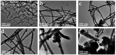 | ||
Fig. 1 TEM micrographs of representative MnO2 nano-structures formed in the presence of I3K nanofibers: (a) MP-2 (0.6 mM manganese precursors, similarly hereinafter), (b) MP-3 (3 mM), (c) MP-4 (6 mM), (d) MP-5 (15 mM), (e) MP-6 (30 mM), (f) MP-7 (60 mM). The peptide concentration was fixed as 1 mM. The molar ratio of KMnO4 and Mn(NO3)2 was fixed as 1![[thin space (1/6-em)]](https://www.rsc.org/images/entities/char_2009.gif) : :![[thin space (1/6-em)]](https://www.rsc.org/images/entities/char_2009.gif) 2 while their total concentration was changed, as indicated in Table 1. 2 while their total concentration was changed, as indicated in Table 1. | ||
At a precursor concentration of 15 mM, the formed MnO2 hybrid (MP-5) showed the most uniform branched nanowire morphology without randomly deposited urchin-like MnO2 spheres and importantly, the sample displayed the best electrochemical properties, as indicated below. Thus, further compositional and structural assessments were focused on the sample. First, the signals of Mn 2p, O 1s, N 1s, and C 1s were clearly observed in the XPS survey spectrum of MP-5 (Fig. 2a). Second, the high-resolution spectrum of Mn 2p indicated two peaks centered at 642.2 and 653.9 eV, which were attributed to Mn 2p3/2 and Mn 2p1/2, respectively. The peaks values and a spin-energy separation of 11.7 eV were well consistent with the reported data of Mn 2p3/2 and Mn 2p1/2 of MnO2.28–32 Third, as reported by Toupin et al. and Chigane et al., the energy separation between the two weak peaks of Mn 3s is 5.41 and 4.78 eV for Mn3+ and Mn4+ oxides, respectively, and a low valence of Mn usually results in a wider splitting of the two Mn 3s peaks.11,33 In this case, the observed value of 4.85 eV was close to that of Mn4+ oxide (4.78 eV) (Fig. 3c). These results suggest the overwhelming predominance of the +4 oxidation state for the manganese oxide deposited along the peptide nanofibers. On the other hand, the slight increase in the Mn 3s energy separation from 4.78 to 4.85 eV was likely to be caused by minor Mn3+ in the deposited MnO2. In fact, it has been reported that some surface Mn3+ (reactive intermediate) remained unoxidized during oxidative precipitation of MnO2 from Mn2+-bearing aqueous solutions.34 The deconvolution of the O 1s spectrum produced a major peak at 529.9 and a minor one on its high binding energy side (531.4 eV), the former corresponding to the Mn–O–Mn bond for the tetravalent oxide while the latter being likely ascribed to the combined effect of the Mn–OH bond for a hydrated trivalent oxide and the H–O–H bond for residual structure water (Fig. 2d).11,34 Thermal gravimetric analysis (TGA) indicated about 10 wt% of residual water in the sample (Fig. S5†).
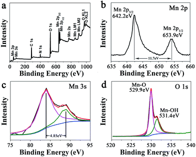 | ||
| Fig. 2 (a) XPS survey spectrum of branched MnO2 nanowires (MP-5) and the narrow XPS spectra of (b) Mn 2p, (c) Mn 3s, and (d) O 1s of MP-5. | ||
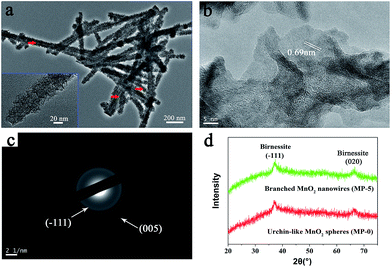 | ||
| Fig. 3 (a) High-magnification TEM image, (b) HR-TEM image, and (c) SAED pattern of branched MnO2 nanowires (MP-5). (d) XRD patterns of MP-5 and MP-0 (urchin-like MnO2 spheres). | ||
High-magnification TEM images clearly indicated that the branched MnO2 nanowires arose from the assembly of small and ultrathin MnO2 nanoflakes along the peptide template (Fig. 3a), and in some cases, the peptide nanofibers were still discernible (red arrows in Fig. 3a). The small nanoflakes were uniformly distributed on the template surface and well interconnected, and their thickness was estimated to be less than 5 nm by measuring the width of black lines (insets of Fig. 3a). HR-TEM characterization showed that the edge of the MnO2 nanoflakes was highly transparent (Fig. 3b), being consistent with their ultrathin thickness. Importantly, HR-TEM and SAED investigations indicated that the branched MnO2 nanostructures had low crystallinity (Fig. 3b and c). In spite of their weak crystalline property, some crystallizing micro-zones in the HR-TEM micrograph revealed a d-spacing of 0.69 nm, being consistent with the interplanar spacing of the (001) plane of birnessite-type MnO2.27,30,35,36 Additionally, X-ray diffraction (XRD) measurements only revealed two weak diffraction peaks for the branched MnO2 nanowires as well as the urchin-like MnO2 spheres, indicating their poor crystallinity (Fig. 3d). The two peaks can be indexed to the (−111) and (020) planes of birnessite-type MnO2 (JCPDS 80-1098). The poor crystallinity of these inorganic nanostructures may be attributed to that the comproportionation reaction rate was too fast to enable well-ordered arrangement during the MnO2 precipitation, as observed in the preparation of core-corona hierarchical MnO2 nanostructures.35 Overall, the results of XPS, TEM, and XRD indicated that the peptide nanofibers mainly directed the morphology and nanostructure of MnO2 precipitates while had little influence on their crystalline nature.
Because the branched MnO2 nanowires were formed through the assembly of numerous small and ultrathin flakes directed by the peptide nanofibers, a large surface area and a porous feature would thus be expected. As shown in Fig. 4a, the N2 adsorption/desorption measurement of MP-5 showed a typical IV-type isotherm with a hysteresis loop in a relative pressure (p/p0) range of 0.4 to 1.0, being consistent with the disordered mesoporous materials.27,28,37 The BET surface area of the branched MnO2 nanowires (MP-5) was calculated to be 275 m2 g−1, which was much higher than that (187 m2 g−1) of urchin-like MnO2 spheres and those of previously reported hybrid nanostructures such as MnO2/SiNWs and MWCNTs@MnO2.27,37 The Barett–Joyner–Halenda (BJH) pore size distribution curve of MP-5 was given in Fig. 4b. A distribution ranging from 3 to 8 nm with a distinct maximum centered at 5 nm was observed. These mesopores corresponded to slit-like pores, as a result of the stacking of numerous small and ultrathin MnO2 nanoflakes.27 The high specific surface area and the mesoporous nature of the branched MnO2 nanowires (MP-5) not only provided more surface active sites for electrochemical reactions but also favored the transport of both electrons and cations (shortening their transport path length), thus most likely endowing them with high specific capacitance. In contrast, the urchin-like MnO2 spheres (MP-0) formed in the absence of peptide has a significantly decreased surface area (187 m2 g−1) and a narrower pore sized distribution with a much smaller maximum centered at 3 nm (Fig. S6†), indicating a dense packing of MnO2 nanoflakes in this case.
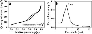 | ||
| Fig. 4 (a) N2 adsorption/desorption isotherm and (b) BJH pore size distribution of branched MnO2 nanowires (MP-5). | ||
Although KMnO4 is a strong oxidant and many studies have utilized the redox reaction between KMnO4 and carbon (e.g. carbon nanotubes and graphene) to prepare supercapacitor electrode materials without any reductant addition under acidic and/or hydrothermal conditions,10,29,30,38–40 there was little redox reaction between KMnO4 and I3K in our case (neutral pH and room temperature), which was confirmed by the XPS analysis on the collected MnO2/peptide hybrid materials. As shown in Fig. S7a,† the deconvolution peaks of N 1s spectrum of MP-5 were at 399.8 and 401.6 eV, which were assigned to the bonding configuration of the amine (–NH2) and the protonated amine (–NH3+) group, respectively. In contrast, there were no XPS signs corresponding to the oxidizing state of N such as NOx. Furthermore, we followed the visible absorption of KMnO4 in different systems. As shown in Fig. S7b,† the absorbance at 526 nm of KMnO4 (5 mM) remained unchanged for the pure KMnO4 solution or little changed in the presence of 1 mM I3K even after 12 hours at room temperature. However, the characteristic absorbance quickly reduced to near zero (typically within 5 minutes) when 10 mM Mn(NO3)2 was introduced (Fig. S7b†), indicating a rapid reaction between the two kinds of manganese precursors. In the present peptide-directed synthesis of MnO2, it was thus unlikely that KMnO4 would react with I3K and instead, it underwent a rapid comproportionation reaction with Mn(NO3)2, leading to the MnO2 deposition along the peptide nanofibers.
Therefore, I3K molecules are suggested to function through self-assembling into nanofibers, which then direct the nucleation and growth of MnO2. The templating ability of the I3K nanofibers may arise from the electrostatic attractions between the positively charged groups (–NH3+) on their surface and the negatively charged MnO4− ions, as well as the interactions (e.g. electrostatic interactions, hydrogen bonding, and van der Waals forces) between the surface groups (–NH2 and –NH3+) and the oligomers of manganese oxides (e.g. tiny nuclei). Portehault et al. have suggested that in the absence of any additives, the growth of MnO2 during the redox reaction between MnO4− and Mn2+ could be divided into two stages: in the first stage, the initial reaction between MnO4− and Mn2+ is too fast to enable the ordered growth and orientation of tiny nuclei, thus leading to the formation of poorly ordered solid spheres, and in the second stage, the slow precipitation kinetics allows the orientated growth of tiny nuclei into small and ultrathin nanoflakes and their subsequent aggregation on the preformed spheres, eventually resulting in the formation of core-corona particles.35 Here, a similar mechanistic process was proposed for the formation of branched MnO2 nanowires, as schematically illustrated in Fig. 5. In the presence of the I3K nanofibers, MnO4− ions would be anchored on their surface predominantly via the electrostatic attraction. At first, the disproportion reaction rapidly occurred between Mn2+ and the surface-enriched MnO4−, resulting in a compact layer of MnO2 along the peptide nanofibers. Then, the small and ultrathin MnO2 nanoflakes resulting from the slow reaction between residual Mn2+ and MnO4− in solution were assembled on the template, eventually leading to the formation of branched MnO2 nanowires. At low concentrations of manganese precursors, a thin and compact MnO2 layer along the peptide nanofibers dominated, because nearly all MnO4− ions were anchored on the template surface and the nucleation speed was greater than the growth speed (Fig. 1a). At higher concentrations of manganese precursors, the templating ability of the peptide nanofibers was saturated, eventually leading to the random deposition of urchin-like MnO2 spheres in addition to branched MnO2 nanowires (Fig. 1f).
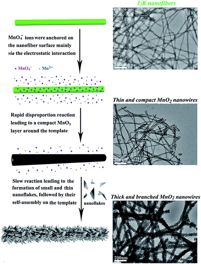 | ||
| Fig. 5 Schematic illustration of the formation process of branched MnO2 nanowires directed by the I3K nanofibers. | ||
Electrochemical performance of MnO2 nanostructures
The electrochemical performances of the above MnO2 nanostructures as the electrode materials for supercapacitors were assessed using the combination of cyclic voltammetry (CV) and galvanostatic charge/discharge techniques. The charge-storage mechanism of MnO2 is known as the ion coupled redox process: MnO2 + Na+ + e− ↔ MnOONa, which is based on the surface adsorption of electrolyte cations (Na+) on MnO2.2,11,41 Fig. 6a shows the CV curves of the MnO2 nanomaterials prepared at different precursor concentrations at a scan rate of 5 mV s−1. These CV curves were close to a rectangular shape, being characteristic of pseudocapacitive oxides.42,43 Furthermore, when the peak current was plotted against the square root of the scan rate in the case of MP-5, a linear relationship was observed between them (Fig. S8†), suggesting a diffusion controlled electrode process.43–45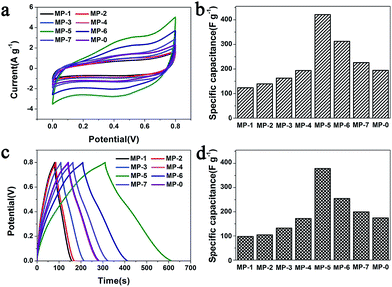 | ||
| Fig. 6 (a) CV curves of different MnO2 nanomaterials as the electrode materials in aqueous 1 M Na2SO4 at scan rates of 5 mV s−1 and (b) the calculated specific capacitances that were calculated according to the eqn (1). (c) Their galvanostatic charge–discharge curves in aqueous 1 M Na2SO4 at a current density of 1 A g−1 and (d) the specific capacitances that were calculated according to the eqn (2). | ||
The specific capacitance (C) was calculated from the CV curves according to the following equation:
 | (1) |
The galvanostatic charge–discharge (GCD) curves at a current density of 1 A g−1 for different MnO2 samples were shown in Fig. 6c. The profiles showed a quasi-linear and symmetric shape, suggesting that all the samples had an excellent reversibility as the electrode materials during the charge/discharge process.10,37,46,47 The specific capacitance (C) can also be calculated from the GCD curves according to the eqn (2):
 | (2) |
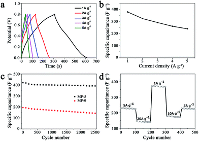
In order to test the rate capability and reversibility of the MP-5 electrode, its galvanostatic charge/discharge curves were recorded at different current densities. As shown in Fig. 7a, these almost symmetrical charge/discharge curves indicated an excellent electrochemical reversibility. Furthermore, MP-5 exhibited 63.2% retention of the initial specific capacitance as the current density was increased from 1 to 5 A g−1 (Fig. 7b), suggesting a reasonable high-rate capability.12,37,48 On the other hand, the effect of the scan rate on the capacitance property of MP-5 was also investigated. It could be seen from Fig. S9† that the CV curves remained approximately rectangular at different scan rates and the specific capacitance attained at 234 F g−1 even at a high scan rate of 100 mV s−1, demonstrating again a good capacitive property and high-rate capability of MP-5 as the electrode material. These reductions can be ascribed to a decrease in the efficiency of active species at higher current densities or scan rates.12
Cycling stability is another crucial parameter for the use of supercapacitors in practical applications. Fig. 7c shows the cycling performance of the electrode prepared from MP-5 nanowires at a scan rate of 5 mV s−1 over 2500 cycles. The specific capacitance slightly decreased during cycling and about 93% of the initial capacitance was retained after 2500 cycles. As for the electrode prepared from the urchin-like MnO2 spheres, approximately 73% of the initial capacitance was kept after 2500 cycles. The results demonstrated an excellent cycling stability of the branched MnO2 nanowire as the electrode material for supercapacitors. Furthermore, the cycling performance of the MP-5 electrode was also evaluated at varied current densities and the results are shown in Fig. 7d. It can be clearly seen that even suffering from sudden change of the current density, the electrode exhibited stable capacitance, and the specific capacitance at 5 A g−1 remained little changed when the current density finally returned to 5 A g−1 after a series of varied current densities, indicating again the excellent cycling of MP-5. Although the exact reason for the excellent cycling stability of MP-5 is currently elusive, it is likely related to the morphology of branched nanowires, which can alleviate the aggregation of nanostructures during the charge and discharge process.
Conclusions
By using the I3K self-assembled nanofibers as the template, MnO2/hybrid nanowires were synthesized through the comproportionation reaction between KMnO4 and Mn(NO3)2 in neutral aqueous solution and at room temperature. Because the underlying mechanism was the interaction between the surface-enriched lysine residues of the template and the precursor as well as the oligomers of manganese oxides in solution, the diameter and the surface morphology of the formed MnO2/hybrid nanowires could be tuned by varying the concentrations of manganese precursors at a fixed peptide concentration. Uniform branched MnO2/peptide hybrid nanowires (MP-5) were obtained when the concentration of I3K, KMnO4 and Mn(NO3)2 was 1, 5, and 10 mM, respectively. The compositional and structural measurements on MP-5 revealed the MnO2 deposition and the subsequent assembly of small and ultrathin MnO2 nanoflakes along the peptide nanofibers, thus endowing the well-ordered hybrid sample with high porosity and a large specific surface area of 275 m2 g−1. As the electrode materials, the branched MnO2 hybrid nanowires (MP-5) exhibited excellent supercapacitance performances. Their specific capacitance could attain at a higher value of 421 F g−1 and retained about 93% of the initial capacitance after 2500 cycles at a scan rate of 5 mV s−1, and remained little changed during the process of progressively varying the current density. Furthermore, the electrode prepared from MP-5 showed an excellent reversibility and a reasonable high-rate capability during the charge/discharge process. The excellent electrochemical properties of the branched MnO2 hybrid nanowires arose from their peculiar architecture and properties, including the branched nanowire morphology, higher porosity, and large specific surface area. By taking advantage of peptide self-assembly, the present study demonstrates a potential methodology to prepare MnO2 nanostructures under mild conditions, which possess excellent electrochemical performances as the electrode materials for supercapacitors.Acknowledgements
This work was supported by the National Natural Science Foundation of China (21673293 and 21103229), the Specialized Research Fund for the Doctoral Program of Higher Education (20130133110011), and the Fundamental Research Funds for the Central Universities (15CX05017A and 14CX02154A).Notes and references
- G. P. Wang, L. Zhang and J. Zhang, Chem. Soc. Rev., 2012, 41, 797–828 RSC.
- W. Wei, X. Cui, W. Chen and D. G. Ivey, Chem. Soc. Rev., 2011, 40, 1697–1721 RSC.
- M. Mastragostino, R. Paraventi and A. Zanelli, J. Electrochem. Soc., 2000, 147, 3167–3170 CrossRef CAS.
- K. R. Prasad and N. Munichandraiah, Electrochem. Solid-State Lett., 2002, 5, A271–A274 CrossRef CAS.
- D. Villers, D. Jobin, C. Soucy, D. Cossement, R. Chahine, L. Breau and D. Bélanger, J. Electrochem. Soc., 2003, 150, A747–A752 CrossRef CAS.
- M. J. Young, A. M. Holder, S. M. George and C. B. Musgrave, Chem. Mater., 2015, 27, 1172–1180 CrossRef CAS.
- J.-H. Kim, K. Zhu, Y. Yan, C. L. Perkins and A. J. Frank, Nano Lett., 2010, 10, 4099–4104 CrossRef CAS PubMed.
- C.-C. Hu, K.-H. Chang, M.-C. Lin and Y.-T. Wu, Nano Lett., 2006, 6, 2690–2695 CrossRef CAS PubMed.
- J. S. Daubert, N. P. Lewis, H. N. Gotsch, J. Z. Mundy, D. N. Monroe, E. C. Dickey, M. D. Losego and G. N. Parsons, Chem. Mater., 2015, 27, 6524–6534 CrossRef CAS.
- J. Yan, Z. Fan, T. Wei, W. Qian, M. Zhang and F. Wei, Carbon, 2010, 48, 3825–3833 CrossRef CAS.
- M. Toupin, T. Brousse and D. Belanger, Chem. Mater., 2004, 16, 3184–3190 CrossRef CAS.
- S. Devaraj and N. Munichandraiah, J. Phys. Chem. C, 2008, 112, 4406–4417 CAS.
- P. K. Nayak and N. Munichandraiah, J. Solid State Electrochem., 2012, 16, 2739–2749 CrossRef CAS.
- C.-C. Hu, Y.-T. Wu and K.-H. Chang, Chem. Mater., 2008, 20, 2890–2894 CrossRef CAS.
- V. Subramanian, H. Zhu, R. Vajtai, P. M. Ajayan and B. Wei, J. Phys. Chem. B, 2005, 109, 20207–20214 CrossRef CAS PubMed.
- S. Zhao, T. Liu, D. Hou, W. Zeng, B. Miao, S. Hussain, X. Peng and M. S. Javed, Appl. Surf. Sci., 2015, 356, 259–265 CrossRef CAS.
- A. Sarkar, A. K. Satpati, V. Kumar and S. Kumar, Electrochim. Acta, 2015, 167, 126–131 CrossRef CAS.
- G. Qiu, H. Huang, S. Dharmarathna, E. Benbow, L. Stafford and S. L. Suib, Chem. Mater., 2011, 23, 3892–3901 CrossRef CAS.
- J.-K. Chang and W.-T. Tsai, J. Electrochem. Soc., 2003, 150, A1333–A1338 CrossRef CAS.
- Q. Li, X.-F. Lu, H. Xu, Y.-X. Tong and G.-R. Li, ACS Appl. Mater. Interfaces, 2014, 6, 2726–2733 CAS.
- M. B. Dickerson, K. H. Sandhage and R. R. Naik, Chem. Rev., 2008, 108, 4935–4978 CrossRef CAS PubMed.
- S. Wang, Q. Cai, M. Du, J. Xue and H. Xu, J. Phys. Chem. B, 2015, 119, 12059–12065 CrossRef CAS PubMed.
- H. Xu, Y. Wang, X. Ge, S. Han, S. Wang, P. Zhou, H. Shan, X. Zhao and J. R. Lu, Chem. Mater., 2010, 22, 5165 CrossRef CAS.
- S. Han, S. Cao, Y. Wang, J. Wang, D. Xia, H. Xu, X. Zhao and J. R. Lu, Chem.–Eur. J., 2011, 17, 13095 CrossRef CAS PubMed.
- S. Wang, X. Ge, J. Xue, H. Fan, L. Mu, Y. Li, H. Xu and J. R. Lu, Chem. Mater., 2011, 23, 2466–2474 CrossRef CAS.
- S. Wang, J. Xue, X. Ge, H. Fan, H. Xu and J. R. Lu, Chem. Commun., 2012, 48, 9415–9417 RSC.
- D. P. Dubal, D. Aradilla, G. Bidan, P. Gentile, T. J. S. Schubert, J. Wimberg, S. Sadki and P. Gomez-Romero, Sci. Rep., 2015, 5, 9771, DOI:10.1038/srep09771.
- B. Li, G. Rong, Y. Xie, L. Huang and C. Feng, Inorg. Chem., 2006, 45, 6404–6410 CrossRef CAS PubMed.
- J. Yan, Z. Fan, T. Wei, J. Cheng, B. Shao, K. Wang, L. Song and M. Zhang, J. Power Sources, 2009, 194, 1202–1207 CrossRef CAS.
- H. Xia, M. Lai and L. Lu, J. Mater. Chem., 2010, 20, 6896–6902 RSC.
- Z. Li, Y. Mi, X. Liu, S. Liu, S. Yang and J. Wang, J. Mater. Chem., 2011, 21, 14706–14711 RSC.
- Z. Li, J. Wang, S. Liu, X. Liu and S. Yang, J. Power Sources, 2011, 196, 8160–8165 CrossRef CAS.
- M. Chigane and M. Ishikawa, J. Electrochem. Soc., 2000, 147, 2246–2251 CrossRef CAS.
- H. W. Nesbitt and D. Banerjee, Am. Mineral., 1998, 83, 305–315 CrossRef CAS.
- D. Portehault, S. Cassaignon, N. Nassif, E. Baudrin and J.-P. Jolivet, Angew. Chem., Int. Ed., 2008, 47, 6441–6444 CrossRef CAS PubMed.
- L. Yu, G. Zhang, C. Yuan and X. W. Lou, Chem. Commun., 2013, 49, 137–139 RSC.
- H. Zheng, J. Wang and C. Ma, J. Power Sources, 2012, 216, 508–514 CrossRef CAS.
- Y. Chen, B. Xie, S. Luo and Y. Zhang, Appl. Surf. Sci., 2013, 285P, 425–430 CrossRef.
- J. Li, N. Wang, Y. Zhao, Y. Ding and L. Guan, Electrochem. Commun., 2011, 13, 698–700 CrossRef CAS.
- S.-B. Ma, K.-Y. Ahn, E.-S. Lee, K.-H. Oh and K.-B. Kim, Carbon, 2007, 45, 375–382 CrossRef CAS.
- D. Bélanger, T. Brousse and J. W. Long, Electrochem. Soc. Interface, 2008, 17, 49–52 Search PubMed.
- T. Brousse, D. Bélanger and J. W. Long, J. Electrochem. Soc., 2015, 162, A5185–A5189 CrossRef CAS.
- B. E. Conway, Electrochemical supercapacitors: scientific fundamentals and technological applications, Kluwer Academic/Plenum Press, New York, 1999 Search PubMed.
- P. Simon, Y. Gogotsi and B. Dunn, Science, 2014, 343, 1210–1211 CrossRef CAS PubMed.
- R. N. Reddy and R. G. Reddy, J. Power Sources, 2004, 132, 315–320 CrossRef CAS.
- Y.-C. Chen, Y.-K. Hsu, Y.-G. Lin, Y.-K. Lin, Y.-Y. Horng, L.-C. Chen and K.-H. Chen, Electrochim. Acta, 2011, 56, 7124–7130 CrossRef CAS.
- S. Chen, J. Zhu, X. Wu, Q. Han and X. Wang, ACS Nano, 2010, 4, 2822–2830 CrossRef CAS PubMed.
- J. Liu, J. Jiang, C. Cheng, H. Li, J. Zhang, H. Gong and H. J. Fan, Adv. Mater., 2011, 23, 2076–2081 CrossRef CAS PubMed.
Footnote |
| † Electronic supplementary information (ESI) available. See DOI: 10.1039/c7ra00829e |
| This journal is © The Royal Society of Chemistry 2017 |

