 Open Access Article
Creative Commons Attribution 3.0 Unported Licence
Electrochemical properties of a silicon nanoparticle/hollow graphite fiber/carbon coating composite as an anode for lithium-ion batteries
Liyong Wang ab,
Zhanjun Liu*a,
Quangui Guoa,
Xiaohui Guoa and
Jianjun Gub
aCAS Key Laboratory of Carbon Materials, Institute of Coal Chemistry, Taiyuan 030001, China. E-mail: zjliu03@sxicc.ac.cn; Fax: +86 351 4084 106
bHebei Normal University for Nationalities, Chengde 067000, China
First published on 25th July 2017
Abstract
Herein, a double strategy to modify the cycling performance of pure silicon nanoparticles (SiPs) was applied. Hollow graphite fibers (HGFs) with a good graphite structure could improve the electrical conductivity of the electrode. The SiP/HGF composite maintained a discharge capacity of 556.2 mA h g−1 and a charge capacity of 548.6 mA h g−1 after 50 cycles at the current density of 50 mA g−1, which obviously promoted the lifetime as compared to that of the anode of pure SiPs. Carbon coating could minimize the direct contact between the SiPs and electrolyte and buffer the volume changes during cycling. The silicon nanoparticle/hollow graphite fiber/carbon-coated (SiP/HGF/C) composite delivered the initial discharge and charge capacities of 1327.2 and 936.6 mA h g−1, respectively, at a current density of 50 mA g−1. After the first cycle, the charge capacity began to steadily increase to 1122.7 mA h g−1 until the thirty-first cycle. The double strategy effectively buffered the volume changes, enhanced the intensity of the electrode, and improved the overall electrical conductivity during discharge–charge cycles. The low-cost SiP/HGF/C composite showed an optimized electrochemical performance as compared to the pure SiP anode.
1. Introduction
With the rapid increase in global energy consumption, the exhaustion of fossil fuels, and increase in environmental problems, energy storage and conversion has become a key issue affecting our daily life.1–3 Rechargeable lithium-ion batteries (LIBs), named by Sony Corp., can store and release electric energy many times and are promising for green energy applications. Carbon materials were first adopted as anode materials for commercialized LIBs, providing safety during application.4 To date, a number of carbon materials have been investigated5 such as graphite,6–8 amorphous carbon,9,10 carbon fibers,11–15 carbon nanotubes,16–23 and graphene.24–33Graphite electrodes were exfoliated in propylene carbonate-based electrolytes; this resulted in drastic decomposition of the electrolyte and thus led to large irreversible capacity. Spherical natural graphite with a carbon coating not only avoids direct contact with the electrolyte, but also achieves excellent electrochemical performance. Spherical carbon-coated natural graphite exhibits a reversible capacity of 360 mA h g−1, and its most coulombic efficiencies are over 90%.34
Nitrogen-doped mesoporous hollow spheres demonstrated high specific surface area and a vegetable sponge-like mesoporous shell with interconnected carbon that facilitated electron transport and Li ion diffusion. They have a capacity of 485 mA h g−1 at a current density of 500 mA g−1 after 1000 cycles. At a higher current density of 4.0 A g−1, these spheres can maintain a rather high capacity of 214 mA h g−1.35
Chen et al.36 have explored a flexible carbon nanotube electrode for LIBs using multiwalled carbon nanotube-entangled networks integrated into a highly conducting carbon layer. The flexible electrode delivers a significant fully reversible capacity of 572 mA h g−1, which is higher than the theoretical capacity of graphite (372 mA h g−1). The good performance of the flexible electrode is ascribed to its novel, three-dimensional porous nanostructure, which provides highly reversible insertion/extraction process of lithium ion onto/from the nanostructured electrode. The special design of the flexible carbon nanotube electrode also provides robustness without the use of any binder or substrate for mechanical integrity.
Junzhong Wang32 has used natural microcrystalline graphite minerals to produce high quality graphene microsheets through a scalable electrochemical and mechanical exfoliation method. The graphene microsheets exhibit a small sheet size of 0.2–0.6 μm2, <5 atomic layers, few defects, and high purity. The graphene anode has a reversible capacity of 390 mA h g−1 at a current density of 40 mA g−1 after 220 cycles that demonstrates its good cyclability. Notably, it retained a specific capacity of 200 mA h g−1 at a higher current density of 595 mA g−1 within 17 min and can be used for high-rate energy storage.
Although graphite has been commercially applied in LIBs, it cannot meet the growing demand for LIBs with higher energy and power densities. Many researchers have tried their best to find advanced anode materials to substitute graphite.37–42 The developed metal oxides,43–47 metal sulfides,48,49 and silicon (Si)50–62 have higher theoretical capacity than graphite. Among these different types of materials, Si has been proposed as the most promising anode material due to its corresponding high theoretical lithium storage capacity (4200 mA h g−1 for Li22Si5), high volumetric capacity (9876 mA h cm−3), and low-cost. However, Si generally induces volume expansion (>300%) during the formation of the LixSi alloy that results in cracking and pulverization, loss of electrical contact, and short cycle life. To overcome the abovementioned limitations, many methods and techniques have been applied to improve the capacity, at various rates, and cycling life of this alloy.
Nanofibers have already been studied as anodes for LIBs. The Si/carbon composite is first spun into nanofibers, which are then coated by reduced graphene oxide.63 They show good electrochemical performance with a high reversible capacity of 1055.1 mA h g−1 after 130 cycles at a current density of 0.1 A g−1. At a higher current density of 5 A g−1, they demonstrate an outstanding reversible capacity of 358.2 mA h g−1. This might be ascribed to the sandwich structure, which maintains structural integrity and improves electrochemical conductivity.
To obtain high-performance anode materials, Li et al. have developed face-to-face contact and open-void coinvolved Si/C nanohybrids as anode materials using a layer of Si anchored onto a three-dimensional graphene/carbon nanotube aerogel framework and well-balanced open voids via chemical vapor deposition method.64 The prepared nanohybrids stabilize the structure of the electrode, resulting in a high reversible discharge capacity of 1498 mA h g−1 at the current density of 200 mA g−1 and excellent rate capability (462 mA h g−1 at current density of 10 A g−1). When cycled at a higher current density of 10 A g−1, the nanohybrids still demonstrate no obvious capacity decay even after 2000 cycles, thus showing perfect cyclability.
The sandwich-structured graphite-metallic Si@C nanocomposites have been prepared using a ball-milling process and further modified by carbon layers.65 As anode materials for LIBs, they improve the electrochemical performance as compared to the pure Si anode. They exhibit a high reversible capacity of 1700 mA h g−1 after 100 cycles at 0.5C with only 0.02% capacity decay per cycle. They also have a good rate capability, with a reversible capacity of 650 and 251.2 mA h g−1 at 1 and 5C, respectively. The advanced structural design provides a highly conductive network and prevents Si pulverization during cycling, which improves the electrochemical performance.
Combining graphite and Si as an integrally bonded anode material for LIBs is a clever technique.66 Ko et al. have synthesized Si-nanolayer-embedded graphite for high-energy lithium-ion batteries. The prepared hybrids completely overcome the detrimental effects arising from volume variation. This structure supports electrical interconnectivity and morphological integrity for the electrode structure. The hybrids show a high first-cycle coulombic efficiency of 92% and high capacity retention of 96% after 100 cycles. With LiCoO2 as a cathode, the full cell delivers a higher energy density (1043 W h I−1) than the current commercial LIBs (900 W h I−1).
The strategy of hybridizing Si and carbon and incorporating Si nanoparticles into void-containing carbon matrices can improve the capacity and cycle life. Taking mass production and production technique into consideration, the involved technology and three-dimensional nanostructure of the electrode are difficult to handle in commercial production. Herein, we demonstrated a hybrid of Si and carbon by simply mixing Si nanoparticles and carbon materials via a thermal treatment. The pitch-based carbon fibers with excellent electrical/thermal conductivity and low density have been in mass production and applied in many different fields in the market. In the hybrids, self-made carbon fibers were used to enhance the electrical contact between Si and the carbon matrix and thereby the electrical conductivity of the anode. Among them, carbon coating derived from a low-cost carbon source via a thermal treatment was prepared to buffer the volume change, to enhance the integrity of the anode during the charge/discharge processes, and also to minimize direct contact between Si and the electrolyte. Taking the double protection for Si nanoparticles into consideration, the Si nanoparticle/hollow graphite fiber/carbon coating (SiP/HGF/C) composites were prepared to possibly replace the commercial graphite anode for rechargeable LIBs. In the SiP/HGF/C composites, SiPs had a weight ratio of 35%. The SiPs were the main contributor to the capacity of the electrode due to their superior high theoretical lithium storage capacity.
2. Experimental
2.1 Raw materials
Si nanoparticles were supplied by Xuzhou Jiechuang New Material Technology Co., Ltd., China. HGFs were made via melt spinning in our laboratory. Low-cost sucrose of 99% purity was purchased from the market. The softening point of the isotropic pitch was 553 K. The isotropic pitch was separated into toluene soluble (TS, 31.08 wt%) and insoluble (TI) fractions. The fraction of TI was separated into quinoline soluble (QS, 46.03 wt%) and insoluble fractions (QI, 22.89 wt%).The isotropic pitch was first spun into fibers using a spinnerette under a nitrogen atmosphere. The as-spun fibers were thermo-oxidatively stabilized at 553 K for 0.5 h in an oxidation oven. The stabilized fibers were carbonized at 1273 K for 0.5 h under a nitrogen atmosphere in a tube furnace. The hollow carbon fibers were finally graphitized at 3073 K for 20 minutes under an argon atmosphere.
The SiP/HGF composite was prepared by simply mixing the SiPs and HGFs (1![[thin space (1/6-em)]](https://www.rsc.org/images/entities/char_2009.gif) :
:![[thin space (1/6-em)]](https://www.rsc.org/images/entities/char_2009.gif) 1 by weight) in ethanol via bath sonication. Then, the mixture was slowly dried in air at room temperature.
1 by weight) in ethanol via bath sonication. Then, the mixture was slowly dried in air at room temperature.
The SiP/HGF/C composite was prepared by simply mixing the SiP/HGF composite and sucrose (7![[thin space (1/6-em)]](https://www.rsc.org/images/entities/char_2009.gif) :
:![[thin space (1/6-em)]](https://www.rsc.org/images/entities/char_2009.gif) 12 by weight) in deionized water via bath sonication. Then, the mixture was carbonized at 1073 K for 0.5 h under a nitrogen atmosphere in a tube furnace.
12 by weight) in deionized water via bath sonication. Then, the mixture was carbonized at 1073 K for 0.5 h under a nitrogen atmosphere in a tube furnace.
2.2 Characterization and electrochemical evaluation
The crystallite structure of materials was characterized between 10 and 90° at the scan rate 5° min−1 via an X-ray diffraction system (XRD; D8 advance, Brucker.) equipped with Cu Kα radiation. The values of interplanar spacing (d002) were characterized. Field-emission scanning electron microscopy (SEM, JSM-7001F) and field-emission transmission electron microscopy (TEM, JEM-2100F) were used to observe the microstructure of the samples.The working electrodes consisted of an active material, acetylene black, and a sodium carboxymethyl cellulose binder in a weight ratio of 7![[thin space (1/6-em)]](https://www.rsc.org/images/entities/char_2009.gif) :
:![[thin space (1/6-em)]](https://www.rsc.org/images/entities/char_2009.gif) 2
2![[thin space (1/6-em)]](https://www.rsc.org/images/entities/char_2009.gif) :
:![[thin space (1/6-em)]](https://www.rsc.org/images/entities/char_2009.gif) 1. CR 2016-type coin cells were assembled in a glovebox under an Ar atmosphere. A Li foil was used as the counter electrode and reference electrode, with a microporous polypropylene film (Celgard 2400) as the separator. The electrolyte was composed of 1 M LiPF6 in ethylene carbonate–dimethyl carbonate (1
1. CR 2016-type coin cells were assembled in a glovebox under an Ar atmosphere. A Li foil was used as the counter electrode and reference electrode, with a microporous polypropylene film (Celgard 2400) as the separator. The electrolyte was composed of 1 M LiPF6 in ethylene carbonate–dimethyl carbonate (1![[thin space (1/6-em)]](https://www.rsc.org/images/entities/char_2009.gif) :
:![[thin space (1/6-em)]](https://www.rsc.org/images/entities/char_2009.gif) 1 by volume) and 5 vol% vinylene carbonate. The cells were galvanostatically discharged and charged using a battery test system (LAND CT 2001A model, Wuhan Jinnuo Electronics Ltd.) in the voltage range of 0.01–2 V at room temperature.
1 by volume) and 5 vol% vinylene carbonate. The cells were galvanostatically discharged and charged using a battery test system (LAND CT 2001A model, Wuhan Jinnuo Electronics Ltd.) in the voltage range of 0.01–2 V at room temperature.
3. Results and discussion
The microstructure of the samples was observed by SEM. The mean particle size of the Si nanoparticles was about 80 nm, and the purity was 99%, as shown in Fig. 1a. HGFs were prepared to be reinforced materials, as shown in Fig. 1b. The external diameter of the GHFs was approximately 19.9 ± 0.6 μm, and their wall thickness was approximately 5.5 ± 0.4 μm. XRD was carried out to further investigate the structure of the samples. Fig. 1c shows typical characteristic peaks assigned to (111), (220), (311), (400), and (422) planes of the crystallized Si nanoparticles. To avoid the shifting and broadening of diffraction profiles, the internal Si standard was used in the XRD analysis. The interplanar spacing of the HGFs was 0.3375 nm, which was indicative of good graphite structure, as shown in Fig. 1d.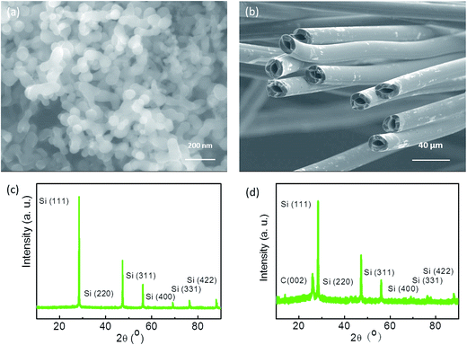 | ||
| Fig. 1 SEM images of (a) Si nanoparticles and (b) HGFs. X-ray diffraction patterns of (c) Si nanoparticles and (d) HGFs. | ||
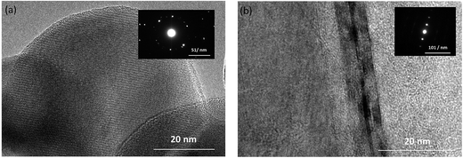
Fig. 2a shows a representative TEM image of the Si nanoparticles. The diffraction spots obtained in the entire area demonstrated a good crystalline microstructure. In Fig. 2b, the graphite stripes of the HGFs highlight the diffraction spots obtained in the entire area, which indicated a highly graphitic structure. The ribbons of the graphite grain of the HGFs can be obviously observed in the Fig. 2b, which indicate that the HGFs can exhibit good extent of graphitization and good electric conductivity.
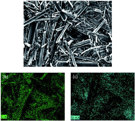
The morphology of the SiP/HGF composite before carbon coating is shown in Fig. 3a. The SiPs dispersed uniformly in the composite and adhered to the surface of the HGFs or dispersed between HGFs. The corresponding elemental mapping of the entire area of Fig. 3a is shown in Fig. 3b and c. Fig. 3b indicates the presence of carbon that originated from the HGFs; Fig. 3c shows the elemental mapping of silicon that originated from the SiPs. The elemental mapping also indicated that the SiPs dispersed well in the composite.
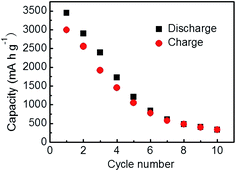
The discharge/charge curve of pure SiPs is shown in Fig. 4. They delivered a first discharge capacity of 3448 mA h g−1 and a charge capacity of 2994 mA h g−1 at a current density of 100 mA g−1. Then, the reversible capacity began to sharply decrease, indicating poor reversibility. After 10 cycles, the reversible capacity was 326.9 mA h g−1, with the irreversible capacity retention of 90% corresponding to the initial cycle performance. Due to pulverization and loss of electrical contact between the active material and the current collector, pure SiPs as an anode material show capacity fading and short battery lifetime.
The strategy to solve these issues to improve the electrochemical performance of pure Si should not only enhance the electrical conductivity of the electrode but also buffer the large volume changes to maintain electrode integrity. Carbon materials were designed to promote the electrical conductivity of the electrode. Graphene has been proven to have unique electrical conductivity due to its special structure and has potential application in electronics as well as energy conversion and storage devices. However, its large surface area results in low initial coulombic efficiency. Moreover, graphene is expensive, which would increase the overall cost of the LIBs. A pitch-based carbon fiber has been recognized as a strategic material due to its high Young's modulus, excellent thermal and electrical conductivity, and low-cost. Self-made HGFs treated at 3073 K show good graphite characteristics and can store Li+; thus, they can be potential reinforced materials for Si-based LIBs.
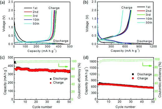
Cycle performance of the HGFs and the SiPs/HGFs was verified at a current density of 50 mA g−1. As reinforced materials, the HGF electrode delivered an initial discharge and charge capacities of 443.7 and 375.1 mA h g−1, respectively, with a coulombic efficiency of 84.5% (Fig. 5a).15,67 The first 10 curves of discharge and charge overlapped quite well, indicating good cycling stability. After 50 cycles, the electrode's reversible capacity is maintained at 338.9 mA h g−1 with steady coulombic efficiency (Fig. 5c).
The SiP/HGF composite exhibited a first discharge capacity of 1164.4 mA h g−1 and a first charge capacity of 709.8 mA h g−1, with a coulombic efficiency 61% (Fig. 5b). The loading density of the active material containing SiPs and HGFs was ∼2.2 mg cm−2. Then, the reversible capacity began to decrease, and a discharge capacity of 556.2 mA h g−1 and a charge capacity of 548.6 mA h g−1 were maintained after 50 cycles, which also prolonged the lifetime of the pure SiPs. The abovementioned results revealed that the SiP/HGF anode had a better cyclability with high reversible capacity than the pure SiP anode. This also indicates that the HGFs not only store/release Li ion, but also improve the lifetime of the anode.
Although the HGFs improved the electrical contact between the SiPs and current collector, the capacity still decreased. This was attributed to the large volume changes of the SiPs. Therefore, a more protective strategy to improve the electrochemical performance of the SiP anode should be developed. An efficient and inexpensive method to buffer the volume changes of SiPs is to use a carbon coating for the SiP/HGF composite.
The cycle performance of the carbon fibers was tested at a current density of 50 mA g−1. Their initial discharge and charge capacities were 371.4 and 205.3 mA h g−1, respectively, with a coulombic efficiency of 55.2% (Fig. 6a). After 50 cycles, the reversible capacity was 188.7 mA h g−1, which was lower than that of the graphitized fibers. This also indicated that the graphitized fibers were superior to be used as anode materials in the composites than the carbon fibers (Fig. 6b).
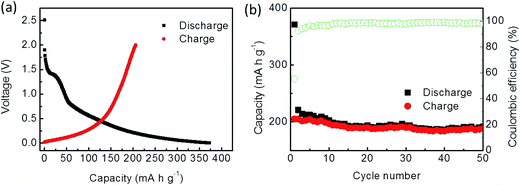 | ||
| Fig. 6 Electrochemical performance of the carbon fibers: (a) charge/discharge curves of the initial cycle and (b) cycling performance. | ||
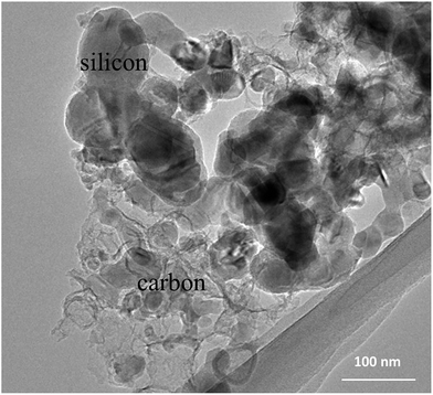
After further protection, TEM was employed to observe the microstructure of the SiP/HGF/C composite. The circular nanoparticles were Si nanoparticles coated with carbon, as displayed in Fig. 7. The corresponding parts are marked in this figure.
The cycle performance of the SiP/HGF/C composite was tested at a current density of 50 mA g−1. The loading density of the active material containing SiPs, HGFs, and C composite was ∼2.4 mg cm−2. Its initial discharge and charge capacities were 1327.2 and 936.6 mA h g−1, respectively, with a coulombic efficiency of 70.6% (Fig. 8a). The second and third charge capacities were 947.8 and 987.2 mA h g−1, respectively. After 10 cycles, the reversible capacity was 1045.2 mA h g−1, which was 11% higher than the initial capacity. The first several curves of discharge and charge overlapped quite well, which indicated good cycling stability of the SiP/HGF/C composite anode. After the first cycle, the charge capacity began to steadily increase to 1122.7 mA h g−1 until the thirty-first cycle (Fig. 8c). This might be attributed to the protection provided by the carbon coating, which effectively buffered the volume changes and enhanced the electrode intensity during discharge–charge cycles. After this, its reversible capacity was maintained at 910.1 mA h g−1 at the 50th cycle, which was higher than that of the SiP/HGF composite.
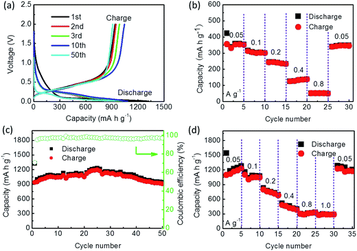 | ||
| Fig. 8 (a) Voltage profiles of the SiP/HGF/C composite. (b) Rate capability of the HGFs. (c) Cycle performance of the SiP/HGF/C composite. (d) Rate capability of the SiP/HGF/C composite. | ||
Rate capability is an important factor for using LIBs in energy storage. The rates for the samples were increased stepwise from 50 mA g−1 to 800 mA g−1 and then switched back. The HGFs reached a reversible capacity of 350.4, 300.3, and 232.7 mA h g−1 after 5, 10, and 15 cycles, respectively. At the densities of 400 and 800 mA g−1, the HGFs obtained the reversible capacities of 137.9 and 49.7 mA h g−1, respectively (Fig. 8b). After the high rate measurements, the HGF electrode tested at 50 mA g−1 achieved a reversible capacity of 345.2 mA h g−1, which was in accordance with the value of the 5th cycle. The good rate capability of this electrode could be helpful for the SiP/HGF/C composite.
The SiP/HGF/C composite delivered the reversible capacities of 1224.6, 1049.1, 679.4, 379.4, and 326.9 mA h g−1 after 5, 10, 15, 20, and 25 cycles, respectively. At the density of 1000 mA h g−1, the SiP/HGF/C composite obtained a reversible capacity of 284.7 mA h g−1. After the high rate measurements, the SiP/HGF/C composite electrode tested at 50 mA g−1 achieved a reversible capacity of 1170.4 mA h g−1, which was close to the value of the 5th cycle (1224.6 mA h g−1) (Fig. 8d). The carbon coating could improve the integrity of the electrode, which was helpful for its good rate capability.
The electrical conductivity of the samples was verified via electrochemical impedance spectroscopy (EIS) measurements, as shown in Fig. 9a. The EIS spectra consisted of two semicircles and a straight sloping line. The first semicircle in the high frequency region may have resulted from the formation of SEI, possibly attributed to their large specific surface area mainly due to an external surface. The second semicircle in the medium frequency region probably resulted because of interfacial charge transfer impedance. The straight sloping line in low frequency region was mainly related to lithium diffusion impedance. The straight diffusion tail suggested that the carbon conductive network facilitated the diffusion and transport of lithium ions between the electrode and the electrolyte and thus reduced lithium ion diffusion resistance. The equivalent circuit is shown in Fig. 9c. Re is the electrolyte resistance and Rct is the charge transfer resistance. Q is the double-layer constant phase angle element and Zw is the Warburg impedance related to the diffusion of lithium ions into the bulk of the composite electrode. C is the capacitance, and Rf is the resistance of the surface film and contact. The values of Rct and Rf for the SiP/HGF/C electrode were 262.7 and 10.7 Ω, respectively. The corresponding relationship between impedance and frequency is displayed in Fig. 9d.
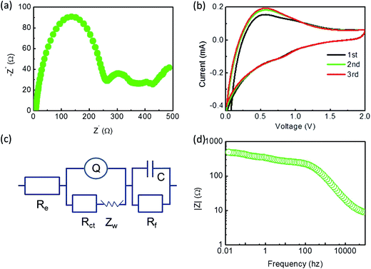 | ||
| Fig. 9 (a) Nyquist plots of the electrodes of the SiP/HGF/C composite, (b) cyclic voltammetry curves of SiP/HGF/C, (c) equivalent circuit of (a), and (d) relationship between impedance and frequency. | ||
A typical cyclic voltammetry (CV) measurement of the electrodes in the voltage range of 0.01–2.0 V at a sweep rate of 1 mV s−1 is shown in Fig. 9b. In the case of the SiP/HGF/C electrode, upon discharge, the current peak appeared at about 0.56 V. In the following anodic scan, the oxidation peaks were nearly consistent with those of the first scan. During the electrode's first cathodic half-cycle, a peak could be clearly seen at about 0.85 V, which could be attributed to the formation of the SEI film that resulted in an initial irreversible capacity.68,69 During the following anodic scan, the corresponding anodic peaks had no obvious shift as compared to those of the first scan. The second and third cathodic–anodic scan curves overlapped quite well, this suggested good cycling performance of the electrode.
4. Conclusions
In conclusion, the double strategy to modify the cycling performance of pure SiPs was applied. The HGFs with a good graphite structure could improve the electrical conductivity of the electrode. The SiP/HGF composite maintained a discharge capacity of 556.2 mA h g−1 and a charge capacity of 548.6 mA h g−1 after 50 cycles at the current density of 50 mA g−1, which obviously prolonged the lifetime of the pure SiPs. Carbon coating was employed to minimize the direct contact between the SiPs and the electrolyte and buffer the volume changes during cycling. The cycle performance of the SiP/HGF/C composite was tested at a current density of 50 mA g−1. Its initial discharge and charge capacities were 1327.2 and 936.6 mA h g−1, respectively, with a coulombic efficiency of 70.6%. After the first cycle, the charge capacity began to steadily increase to 1122.7 mA h g−1 until the thirty-first cycle. After this, its reversible capacity maintained at 910.1 mA h g−1 at 50th cycle with steady coulombic efficiency. This was attributed to the protection provided by the carbon coating and the addition of the HGFs, which effectively buffered the volume changes, enhanced the intensity of electrode, and improved the electrical conductivity during discharge–charge cycles; this resulted in high reversible capacity, good cycling stability, and good rate capability as compared to those of the pure SiP anode. The SiP/HGF/C composites are a promising choice to prepare a low-cost anode material for the LIBs.Acknowledgements
This work was supported by the Project of Scientific Technological Research and Development Plan of Chengde (201608B004, 20155006), the Science and Technological Research Project for University of Hebei Province (ZD2017310), the Hebei Normal University for Nationalities Foundation for Youths (QN201505), and the National Science and Technological Support Project (2015BAH43F00).References
- J. M. Tarascon and M. Armand, Nature, 2001, 414, 359–367 CrossRef CAS PubMed.
- M. Armand and J. M. Tarascon, Nature, 2008, 451, 652–657 CrossRef CAS PubMed.
- P. G. Bruce, B. Scrosati and J. M. Tarascon, Angew. Chem., Int. Ed., 2008, 47, 2930–2946 CrossRef CAS PubMed.
- Y. P. Wu, E. Rahm and R. Holze, J. Power Sources, 2003, 114, 228–236 CrossRef CAS.
- S. Xin, Y. G. Guo and L. J. Wan, Acc. Chem. Res., 2012, 45, 1759–1769 CrossRef CAS PubMed.
- H. Y. Lee, J. K. Baek, S. M. Lee, H. K. Park, K. Y. Lee and M. H. Kim, J. Power Sources, 2004, 128, 61–66 CrossRef CAS.
- D. Goers, M. E. Spahr, A. Leone, W. Märkle and P. Novák, Electrochim. Acta, 2011, 56, 3799–3808 CrossRef CAS.
- H. Abe, K. Zaghib, K. Tatsumi and S. Higuchi, J. Power Sources, 1995, 54, 236–239 CrossRef CAS.
- A. Emori, A. Kudou and T. Horiba, Carbon, 2007, 45, 2857–2858 CrossRef.
- W. Guo, X. Li, J. Xu, H. K. Liu, J. Ma and S. X. Dou, Electrochim. Acta, 2016, 188, 414–420 CrossRef CAS.
- J. K. Lee, K. W. An, J. B. Ju, B. W. Cho, W. I. Cho, D. Park and K. S. Yun, Carbon, 2001, 39, 1299–1305 CrossRef CAS.
- S.-H. Yoon, C.-W. Park, H. Yang, Y. Korai, I. Mochida, R. T. K. Baker and N. M. Rodriguez, Carbon, 2004, 42, 21–32 CrossRef CAS.
- V. Subramanian, H. Zhu and B. Wei, J. Phys. Chem. B, 2006, 110, 7178–7183 CrossRef CAS PubMed.
- I. Cameán, A. B. García, I. Suelves, J. L. Pinilla, M. J. Lázaro and R. Moliner, J. Power Sources, 2012, 198, 303–307 CrossRef.
- L. Wang, Z. Liu, Q. Guo, G. Wang, J. Yang, P. Li, X. Wang and L. Liu, Electrochim. Acta, 2016, 199, 204–209 CrossRef CAS.
- S. Zhong, J. Hu, Z. Wu and W. Mei, Carbon, 2015, 81, 852 CrossRef.
- J. Chen, Y. Liu, A. I. Minett, C. Lynam, J. Wang and G. G. Wallace, Chem. Mater., 2007, 19, 3595–3597 CrossRef CAS.
- C. Zhong, J. Z. Wang, D. Wexler and H. K. Liu, Carbon, 2014, 66, 637–645 CrossRef CAS.
- A. P. Cohn, L. Oakes, R. Carter, S. Chatterjee, A. S. Westover, K. Share and C. L. Pint, Nanoscale, 2014, 6, 4669–4675 RSC.
- Y. Zhang, W. Bai, J. Ren, W. Weng, H. Lin, Z. Zhang and H. Peng, J. Mater. Chem. A, 2014, 2, 11054–11059 CAS.
- J. Mun, J. H. Park, W. Choi, A. Benayad, J. H. Park, J. M. Lee, S. G. Doo and S. M. Oh, J. Mater. Chem. A, 2014, 2, 19670–19677 CAS.
- J. W. Hu, Z. P. Wu, S. W. Zhong, W. B. Zhang, S. Suresh, A. Mehta and N. Koratkar, Carbon, 2015, 87, 292–298 CrossRef CAS.
- R. Paul, V. Etacheri, V. G. Pol, J. Hu and T. S. Fisher, RSC Adv., 2016, 6, 79734–79744 RSC.
- R. Raccichini, A. Varzi, V. S. K. Chakravadhanula, C. Kübel and S. Passerini, Sci. Rep., 2016, 6, 23585 CrossRef CAS PubMed.
- J. Qin, C. He, N. Zhao, Z. Wang, C. Shi, E. Z. Liu and J. Li, ACS Nano, 2014, 8, 1728–1738 CrossRef CAS PubMed.
- Y. Chen, J. Zhu, B. Qu, B. Lu and Z. Xu, Nano Energy, 2014, 3, 88–94 CrossRef CAS.
- G. Kucinskis, G. Bajars and J. Kleperis, J. Power Sources, 2013, 240, 66–79 CrossRef CAS.
- H. Yu, G. Guo, L. Ji, H. Li, D. Yang, J. Hu and A. Dong, Nano Res., 2016, 9, 3757–3771 CrossRef CAS.
- H. Yu, G. Guo, L. Ji, H. Li, D. Yang, J. Hu and A. Dong, Nano Res., 2016, 9, 1–15 CrossRef.
- R. Mo, Y. Du, D. Rooney, G. Ding and K. Sun, Sci. Rep., 2016, 6, 19843 CrossRef CAS PubMed.
- L. Jiao, T. Wu, H. Li, F. Li and L. Niu, Chem. Commun., 2015, 51, 15979–15981 RSC.
- J. Wang, J. Huang, R. Yan, F. Wang, W. Cheng, Q. Guo and J. Wang, J. Mater. Chem. A, 2015, 3, 3144–3150 CAS.
- L. Zhan, S. Yang, Y. Wang, Y. Wang, L. Ling and X. Feng, Adv. Mater. Interfaces, 2014, 1, 274–276 Search PubMed.
- M. Yoshio, H. Wang and K. Fukuda, Angew. Chem., Int. Ed., 2003, 42, 4203–4206 CrossRef CAS PubMed.
- K. Huo, W. An, J. Fu, B. Gao, L. Wang, X. Peng, G. J. Cheng and P. K. Chu, J. Power Sources, 2016, 324, 233–238 CrossRef CAS.
- J. Chen, A. I. Minett, Y. Liu, C. Lynam, P. Sherrell, C. Wang and G. G. Wallace, Adv. Mater., 2008, 20, 566–570 CrossRef CAS.
- U. Kasavajjula, C. Wang and A. J. Appleby, J. Power Sources, 2007, 163, 1003–1039 CrossRef CAS.
- W. Zhang, J. Power Sources, 2011, 196, 13–24 CrossRef CAS.
- X. W. Zhang, P. K. Patil, C. Wang, A. J. Appleby, F. E. Little and D. L. Cocke, J. Power Sources, 2004, 125, 206–213 CrossRef CAS.
- Y. Liu, W. Zhang, Y. Zhu, Y. Luo, Y. Xu, A. Brown, J. N. Culver, C. A. Lundgren, K. Xu, Y. Wang and C. Wang, Nano Lett., 2012, 13, 293–300 CrossRef PubMed.
- A. S. Arico, P. Bruce, B. Scrosati, J. M. Tarascon and W. van Schalkwijk, Nat. Mater., 2005, 4, 366–377 CrossRef CAS PubMed.
- Y. M. Chiang, Science, 2010, 330, 1485–1486 CrossRef CAS PubMed.
- S. K. Park, C. Y. Seong, S. Yoo and Y. Piao, Energy, 2016, 99, 266–273 CrossRef CAS.
- D. Wang, H. He, L. Han, R. Lin, J. Wang, Z. Wu, H. Liu and H. L. Xin, Nano Energy, 2016, 20, 212–220 CrossRef CAS.
- J. Yue, X. Gu, L. Chen, N. Wang, X. Jiang, H. Xu, J. Yang and Y. Qian, J. Mater. Chem. A, 2014, 2, 17421–17426 CAS.
- W. Zhang and D. Liu, Electrochim. Acta, 2015, 156, 53–59 CrossRef CAS.
- M. Y. Son, J. H. Kim and Y. C. Kang, Electrochim. Acta, 2014, 116, 44–50 CrossRef CAS.
- X. Xu, W. Liu, Y. Kim and J. Cho, Nano Today, 2014, 9, 604–630 CrossRef CAS.
- L. Fei, B. P. Williams, S. H. Yoo, J. M. Carlin and Y. L. Joo, Chem. Commun., 2016, 52, 1501–1504 RSC.
- B. Wang, X. Li, B. Luo, X. Zhang, Y. Shang, A. Cao and L. Zhi, ACS Appl. Mater. Interfaces, 2013, 5, 6467–6472 CAS.
- L. Xue, G. Xu, Y. Li, S. Li, K. Fu, Q. Shi and X. Zhang, ACS Appl. Mater. Interfaces, 2012, 5, 21–25 Search PubMed.
- X. H. Liu, L. Zhong, S. Huang, S. X. Mao, T. Zhu and J. Y. Huang, ACS Nano, 2012, 6, 1522–1531 CrossRef CAS PubMed.
- B. Wang, X. Li, X. Zhang, B. Luo, M. Jin, M. Liang, S. A. Dayeh, S. T. Picraux and L. Zhi, ACS Nano, 2013, 7, 1437–1445 CrossRef CAS PubMed.
- H. Li, C. Lu and B. Zhang, Electrochim. Acta, 2014, 120, 96–101 CrossRef CAS.
- B. S. Lee, S. B. Son, K. M. Park, J. H. Seo, S. H. Lee, I. S. Choi, K. H. Oh and W. R. Yu, J. Power Sources, 2012, 206, 267–273 CrossRef CAS.
- B. Liu, X. Wang, H. Chen, Z. Wang, D. Chen, Y. B. Cheng, C. Zhou and G. Shen, Sci. Rep., 2013, 3, 1622 CrossRef PubMed.
- A. M. Chockla, J. T. Harris, V. A. Akhavan, T. D. Bogart, V. C. Holmberg, C. Steinhagen, C. B. Mullins, K. J. Stevenson and B. A. Korgel, J. Am. Chem. Soc., 2011, 133, 20914–20921 CrossRef CAS PubMed.
- L.-F. Cui, Y. Yang, C.-M. Hsu and Y. Cui, Nano Lett., 2009, 9, 3370–3374 CrossRef CAS PubMed.
- T. H. Hwang, Y. M. Lee, B.-S. Kong, J.-S. Seo and J. W. Choi, Nano Lett., 2012, 12, 802–807 CrossRef CAS PubMed.
- N. Liu, Z. Lu, J. Zhao, M. T. McDowell, H. W. Lee, W. Zhao and Y. Cui, Nat. Nanotechnol., 2014, 9, 187–192 CrossRef CAS PubMed.
- L. Wang, Q. Guo, J. Wang, H. Li, G. Wang, J. Yang, Y. Song, Y. Qin and L. Liu, RSC Adv., 2014, 4, 40812–40815 RSC.
- X. Dong, C. Lu, L. Wang, P. Zhou, D. Li, L. Wang, G. Wu and Y. Li, RSC Adv., 2016, 6, 12737–12743 RSC.
- Y. Chen, Y. Hu, Z. Shen, R. Chen, X. He, X. Zhang, Y. Zhang and K. Wu, Electrochim. Acta, 2016, 210, 53–60 CrossRef CAS.
- S. Jing, H. Jiang, Y. Hu, J. Shen and C. Li, Adv. Funct. Mater., 2015, 25, 5395–5401 CrossRef CAS.
- Z. Sun, G. Wang, T. Cai, H. Ying and W. Han, Electrochim. Acta, 2016, 191, 299–306 CrossRef CAS.
- M. Ko, S. Chae, J. Ma, N. Kim, H. W. Lee, Y. Cui and J. Cho, Nat. Energy, 2016, 1, 16113 CrossRef CAS.
- Y.-P. Wu, C. R. Wan, C. Y. Jiang, S. B. Fang and Y. Y. Jiang, Carbon, 1999, 37, 1901–1908 CrossRef CAS.
- H. W. Ping Liu, J. Power Sources, 1995, 56, 81 CrossRef.
- J. Graetz, C. C. Ahn, R. Yazami and B. Fultz, Electrochem. Solid-State Lett., 2003, 6, A194 CrossRef CAS.
| This journal is © The Royal Society of Chemistry 2017 |

