 Open Access Article
Creative Commons Attribution 3.0 Unported Licence
Study on the structural design and performance of novel braid-reinforced and thermostable poly(m-phenylene isophthalamide) hollow fiber membranes†
Mingxing Chen,
Changfa Xiao *,
Chun Wang and
Hailiang Liu
State Key Laboratory of Separation Membranes and Membrane Processes, School of Material Science and Engineering, Tianjin Polytechnic University, Tianjin 300387, China. Web: xiaochangfa@163.com Tel: +86 022-83955299
First published on 7th April 2017
Abstract
Novel braid-reinforced (BR) and thermostable poly(m-phenylene isophthalamide) (PMIA) hollow fiber membranes comprising reinforced braids and a separation layer were prepared by a dry–wet spinning process for the first time. The effects of PMIA concentration and the braid composition on the structure and performance of the BR PMIA hollow fiber membranes were investigated. Field emission scanning electron microscopy (FESEM) was used to observe the morphologies of the BR PMIA hollow fiber membranes. An increase in PMIA concentration resulted in an increase of the protein rejection rate and a decrease in the pure water flux. The higher flux recovery rate indicated that the BR PMIA membranes had excellent antifouling property compared to commercial PVDF membranes. In the BR PMIA membranes existed favorable interfacial bonding between the separation layer and the reinforced braids as the tensile strength of the BR PMIA membranes exceeded 170 MPa. Moreover, when the operating temperature was increased from 25 °C to 90 °C, the water flux increased more than two-fold with stable ink solution rejection, which showed an excellent thermal stability.
Introduction
The demand for fresh water has increased with rapid population growth. Therefore, water reclamation technologies have been receiving increasing attention in recent years. The membrane bioreactor (MBR) has become the first choice for water reclamation due to its lower operating costs and high efficiency.1 Almost all the currently available commercial MBR processes employ membrane modules as the filter to obtain clarified and disinfected water. Hollow fiber membranes have been generally used in MBR technology2–5 as they are mechanically self-supporting and easily assembled in modules for different membrane applications.6 Although hollow fiber membranes have many advantages, their applications are sometimes limited by problems of low tensile strength and as they can be easily damaged in MBR operation.7Some studies have been done to promote the mechanical properties of hollow fiber membranes,8–11 such as the reinforced membrane, which displays good tensile strength and a self-supporting capability. However, a problem still remains that the separation layer could be easily peeled from the reinforced matrix of this kind of hollow fiber membrane, which was termed as a heterogeneous reinforced (HTR) hollow fiber membrane, as the separation layer and reinforced matrix are incompatible. It is desirable that the homogeneous reinforced (HMR) hollow fiber membrane uses the same material between the reinforced matrix and the separation layer to enhance the interfacial bonding. Fan12,13 prepared HMR cellulose acetate (CA) hollow fiber membranes by coating CA solution onto the CA hollow tubular braids. Liu14,15 and Zhang7,16 fabricated reinforced polyvinyl chloride (PVC) and reinforced polyvinylidene fluoride (PVDF) hollow fiber membranes, respectively, and found that the HMR membranes had a more favorable interfacial bonding between the reinforced matrix and the separation layer compared with HTR membranes.
The thermally stable membranes have recently gained significant attention for their advantages, such as flux enhancement, heat recovery, high temperature cleaning, and pasteurization, while commercial membranes can only be applied below the temperature of 50 °C.17 Although ceramic membranes still have undeniable advantages in terms of thermal stability, the high cost and difficult manufacturing process remain critical problems limiting their wide use. Thus it is valuable to develop polymeric membranes with outstanding thermal stability. Some research has been done to develop polymeric membranes with excellent thermal stability, such as polybenzimidazole (PBI),18,19 poly(phthalazine ether sulfone ketone) (PPESK),20,21 sulfonated poly(phthalazinone ether sulfone) (SPPES),22 poly(phthalazione ether nitrile ketone) (PPENK),23 poly(phthalazinone ether amide) (PPEA),24 and poly(pyromellitic dianhydride-co-4,4-oxydianiline) (PMDA/ODA PI).25 However, the poorer hydrophilic property and higher price of these materials limit their application.
Poly(m-phenylene isophthalamide) (PMIA) is one of the most important aromatic polyamides and has been used widely in nanofibers for its high thermal stability combined with excellent mechanical properties.26–31 The chemical structure formula and thermodynamics performance of PMIA are shown in Fig. 1, S1 and S2.† The aramid groups and hydrogen bond network in PMIA contribute to its outstanding thermal stability, hydrophilic property, and mechanical properties. Studies focused on the application of PMIA membranes in water treatment have achieved a certain level of development in the last few years. Ren32 and Huang33 successfully fabricated a PMIA nanofiltration membrane via a phase inversion method, which demonstrated high performance when it was used in removing chromium(VI) from chromium-containing wastewater and in applications of dye purification and desalination. Wang34 fabricated a PMIA hollow fiber nanofiltration membrane by dry–wet spinning technology. The effects of non-solvent additives on the morphology and separation performance were studied. The results indicated that it is possible to fabricate PMIA hollow fiber NF membranes with desired structures and separation performances by adding proper concentrations of LiCl, acetone, and PVP in the doping solution. In another study by Wang,35 a PMIA hollow fiber membrane was used for the removal of perfluorooctane sulfonate from water. The result suggested that the PMIA hollow fiber membrane had potential for applications in the removal of perfluorooctane sulfonate from water. Yang36 prepared a novel PMIA/GO composite nanofiltration membrane via a phase inversion method. The novel PMIA/GO composite nanofiltration membrane showed higher water flux and an excellent antifouling performance due to the addition of GO, which showed its potential for application in water treatment. Lin37 fabricated a PMIA ultrafiltration membrane via a phase inversion method. In this study, the PMIA membrane was found to break through the trade-off between selectivity and permeability. However, to the best of our knowledge, reinforced PMIA hollow fiber membranes and their thermal stability have never been studied before.
In the present study, the braid-reinforced (BR) PMIA hollow fiber membranes were prepared by a dry–wet spinning process and their properties were evaluated by analyzing their morphology, permeability, mechanical property, antifouling property, and thermal stability. The effects of polymer concentration and the composition of the reinforced braids on the structure and performance of the BR PMIA hollow fiber membranes are discussed herein.
Experimental
Materials
Poly(m-phenylene isophthalamide) (PMIA, fiber grade, Mw = 140![[thin space (1/6-em)]](https://www.rsc.org/images/entities/char_2009.gif) 000 Da) was purchased from SRO Aramid Co. Ltd. (Huaian, China). Poly(ethylene glycol) (PEG, Mw = 2000), N,N-dimethylacetamide (DMAc), calcium chloride(CaCl2), and lithium chloride(LiCl) were purchased from Tianjin Kermel Chemical Reagent Co. Ltd. (Tianjin, China). Polyvinylpyrrolidone (PVP, Analytical Reagent, K30, Mw = 30
000 Da) was purchased from SRO Aramid Co. Ltd. (Huaian, China). Poly(ethylene glycol) (PEG, Mw = 2000), N,N-dimethylacetamide (DMAc), calcium chloride(CaCl2), and lithium chloride(LiCl) were purchased from Tianjin Kermel Chemical Reagent Co. Ltd. (Tianjin, China). Polyvinylpyrrolidone (PVP, Analytical Reagent, K30, Mw = 30![[thin space (1/6-em)]](https://www.rsc.org/images/entities/char_2009.gif) 000) were bought from BASF Chemical Industrial Co. Ltd. (Ludwigshafen, Germany). Bovine serum albumin (BSA, Mw = 68
000) were bought from BASF Chemical Industrial Co. Ltd. (Ludwigshafen, Germany). Bovine serum albumin (BSA, Mw = 68![[thin space (1/6-em)]](https://www.rsc.org/images/entities/char_2009.gif) 000) was purchased from Beijing Newprobe Bioscience Co., Ltd. (Beijing, China). The commercial PVDF membrane was provided by OriginWater Technology Co. Ltd. (Beijing China). PMIA filament (PMIA fiber) was purchased from Yantai Tayho Advanced Materials Co. Ltd. (Yantai, China). PET filament (PET fiber) was purchased from Rong Sheng Chemical Fiber Co. Ltd. (Hangzhou, China). The parameters of the PMIA and PET filaments are shown in Table S1.†
000) was purchased from Beijing Newprobe Bioscience Co., Ltd. (Beijing, China). The commercial PVDF membrane was provided by OriginWater Technology Co. Ltd. (Beijing China). PMIA filament (PMIA fiber) was purchased from Yantai Tayho Advanced Materials Co. Ltd. (Yantai, China). PET filament (PET fiber) was purchased from Rong Sheng Chemical Fiber Co. Ltd. (Hangzhou, China). The parameters of the PMIA and PET filaments are shown in Table S1.†
Membrane preparation
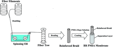
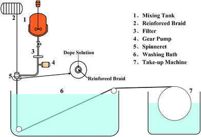
The BR PMIA hollow fiber membranes were prepared via a dry–wet spinning process. The preparation process of the BR PMIA hollow fiber membranes is listed in Fig. 2. Fig. 3 shows the apparatus used in the dry–wet spinning process. The preparation process for the BR PMIA hollow fiber membranes was divided into four steps: First, two bundles of fibers were combined into one fiber tow. After that, the reinforced hollow tubular braids (Fig. S3†) were prepared by using a braiding machine (Fig. S4†) with 24 fiber tows. Second, the reinforced braids went through the spinneret device. In this step, the reinforced braids were integrated with the PMIA doping solutions. The compositions of the PMIA doping solutions are shown in Table 1. Third, the reinforced braids were integrated with the doping solutions in the coagulation bath. The composition of the coagulation bath was water and the temperature was 25 °C. The air gap was 15 cm and the take up speed was 50 cm min−1. Finally, the prepared BR PMIA membranes were stored in distilled water for more than 24 h to remove the residual solvents and water soluble additives. During the following discussion, PMIA15 and M1 are used to refer to the same membrane.| Membrane ID | PMIA (wt%) | PVP (wt%) | PEG (wt%) | CaCl2 (wt%) | LiCl (wt%) | DMAc (wt%) | Braids compositions PMIA/PET |
|---|---|---|---|---|---|---|---|
| PMIA5 | 5 | 2 | 8 | 3.5 | 2.5 | 79 | 2/0 |
| PMIA8 | 8 | 2 | 8 | 3.5 | 2.5 | 76 | 2/0 |
| PMIA10 | 10 | 2 | 8 | 3.5 | 2.5 | 74 | 2/0 |
| PMIA15 | 15 | 2 | 8 | 3.5 | 2.5 | 69 | 2/0(M1), 1/1(M2), 0/2(M3) |
Membrane characterizations
The morphologies of the membranes were observed by scanning electron microscopy (SEM) using an Hitachi S-4800 instrument. The samples were all freeze-dried for more than 24 h. Then, they were cut off and sputtered with gold before the SEM analysis.The water contact angle of the membrane was measured using a contact angle goniometer (Kruss DSA-100, Germany). The average contact angle was calculated with five water contact angles at different locations in order to get a reliable value.
The surface charge of the membranes was determined by measurement of the zeta potentials with the streaming potential method. The measurements were carried out at a temperature of 25 °C in KCl solution (0.001 M, 500 mL) with the pH ranging from 11 to 4 with an electrokinetic analyzer (SurPASS, Anton Paar, Austria).
The pore size and distribution of the membranes were measured by a mercury porosimeter (AutoPore IV 9500, Micromeritics, USA). The samples were all freeze-dried for more than 24 h before testing.
The pure water flux (PWF) of the membranes was measured using a cross-flow filtration system (Fig. S5†) at an outside pressure of 0.1 MPa, and then calculated using eqn (1):
 | (1) |
The BSA rejection and antifouling tests were measured with 1 g L−1 BSA aqueous solution at 0.1 MPa. The flux of the BSA solution was recorded as J1. The rejection was calculated by eqn (2):
 | (2) |
After the BSA fouled membranes were washed with unionized water, the pure water flux of the cleaned membranes (J2) was measured again. The flux recovery ratio (FRR) was calculated by eqn (3):38,39
 | (3) |
To further analyze the antifouling properties of the membranes in detail, several ratios, including the total flux decline ratio (DRt), the reversible decline ratio (DRr), and the irreversible decline ratio (DRir), were defined and calculated as follows:39,40
 | (4) |
 | (5) |
 | (6) |
The mechanical property of the hollow fiber membranes was evaluated by using a universal material testing machine (5969, INSTRON Corporation, America) with a loading velocity of 5 mm min−1 and an initial length of 30 mm. Every sample was tested more than five times.
The bursting strength is the pressure required to rupture a membrane. The bursting strength of the hollow fiber membranes was measured using the apparatus shown in Fig. S6,† comprising a dead-end filtration system under the condition of inside pressure.
In order to evaluate the thermal stability of the membrane, the ink solution was used as the filtration solution. During the test, the operation temperature was raised from 25 °C to 90 °C, while the water flux and the rejection were tested, respectively. The particle distribution and standard concentration absorbance curve of the ink solution are shown in Fig. S7 and S8.† The commercial PVDF membrane and PMIA hollow fiber membrane without braid reinforcement were tested as a control under the same conditions.
Result and discussion
Morphology of the membranes
The morphologies of the BR PMIA hollow fiber membrane with various concentrations of PMIA in the doping solution are shown in Fig. 4. It can be seen that the BR PMIA hollow fiber membranes consisted of the reinforced braids and a separation layer. As shown in Fig. 4b, the separation layer of BR PMIA hollow fiber membranes exhibited an obvious finger-like pore structure. As the PMIA concentration is increased, the finger-like pore structure gradually fades away, while the sponge-like pore structure is improved. Moreover, it can be seen from Fig. 4c that the skin layer became dense as the PMIA concentration increased in the doping solutions. Therefore, one could reach a conclusion that a low PMIA concentration in the doping solution tends to precipitate in a finger-like pore structure and a porous skin layer, while high PMIA concentration tend to form a sponge-like pore structure and a dense skin layer. The higher polymer concentration generally increases the viscosity of doping solution, which slows down the rate of double-diffusion among the solvent and non-solvent in the phase inversion process.41,42 Under conditions of instantaneous demixing, membranes with a relatively porous skin layer and a finger-like pore structure are supposed to be formed, whereas delayed demixing would result in membranes with a relatively dense skin layer and a sponge-like pore structure.43–45 As a result, the desired pore structures were formed. It also could be seen that the infiltration of the doping solution promoted a good interfacial bond between the separation layer and the reinforced braid of the membranes during the preparation process.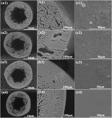 | ||
| Fig. 4 The morphologies of the BR PMIA hollow fiber membranes: (a) cross-section, (b) partial enlargement of the cross-section, (c) outer surface of: (1) PMIA5, (2) PMIA8, (3) PMIA10, (4) PMIA15. | ||
The outer surface morphologies of the BR PMIA hollow fiber membrane are shown in Fig. 4c, where it can be seen that the outer surface became denser and smoother as the PMIA concentration increased in the doping solutions. This is beneficial to improving the rejection and antifouling ability of the membrane, though it would lead to a lower flux.
The cross-sectional morphologies of the BR PMIA hollow fiber membrane with various braid compositions are shown in Fig. 5. The reinforced braid of M1, M2, and M3 were prepared with the PMIA filament, PMIA/PET filament, and PET filament, respectively. As shown in Fig. 5, the separation layer of M1 was tightly bonded with the reinforced braid as they were homogeneous, which ensures a good compatibility. M3, on the other hand, had a poor interfacial boding state as the PET reinforced braid and separation layer were heterogeneous, which means a poor compatibility. For M2, whose reinforced braid was prepared by the PMIA/PET filament, both phenomena existed and it could be seen that the separation layer tightly bonded with the PMIA fibers, while at the same time it had a poor interfacial bonding state with the PET fibers. Moreover, the M1 membranes, which belonged to HMR hollow fiber membranes, did not exhibit a dense region formed by the swelling of the PMIA fibers like the other HMR hollow fiber membranes,13 which was beneficial to the permeability of the membranes. This was because it was a little bit difficult for DMAc in the doping solution to swell the PMIA fiber in such a short time. That was also the reason why we added LiCl and CaCl2 to the DMAc solution when we prepared the doping solution.46 So we considered that the effort of the hybrid braid combined with the PET and PMIA fibers may have no significance in the present work compared to others,12 though it would reduce the cost of the BR PMIA hollow fiber membranes. The reinforced braid prepared with the PMIA filament was thus employed in our following study. Some characterizations of the BR PMIA hollow fiber membranes are shown in Table S2.†
Surface properties
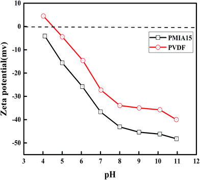
In order to evaluate the surface properties of the BR PMIA membranes, the contact angle and zeta potential were both measured. The zeta potentials of the membrane surface were measured with the pH ranging from 11 to 4. The results are shown in Fig. 6. The results of the contact angles measurements are presented in Table 2. It can be seen that there was a slight change about the contact angle as the PMIA concentration increased, and a good hydrophilicity was shown as the contact angles were lower than 55°, while the contact angle of PVDF was 75°. As shown in Fig. 6, the zeta potential decreased as the pH increases. This is a typical characteristic of polymeric membranes.47 Moreover, the PMIA membranes demonstrated a higher negativity charge than the PVDF membranes. This was because of the strong polar amide groups (–NH–CO–) existing in the PMIA macromolecular chain, which provided the PMIA membranes with strong electronegativity and excellent hydrophilicity. These are often a key goal to reduce membrane fouling and to improve the antifouling property.| Membrane ID | PMIA5 | PMIA8 | PMIA10 | PMIA15 | PVDF |
|---|---|---|---|---|---|
| Contact angle (°) | 50.4 ± 2.58 | 53.8 ± 2.25 | 52.9 ± 3.46 | 54.8 ± 2.51 | 75 ± 3.26 |
Permeation characterization
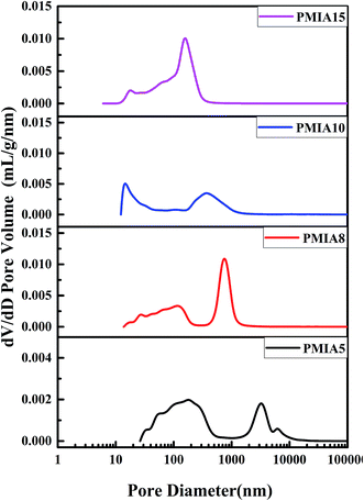
The pore size and distribution of the BR PMIA hollow fiber membranes are shown in Fig. 6. The values of the average pore diameter of the BR PMIA hollow fiber membranes are shown in Table 3. As shown in Fig. 7, the pore size distribution became narrower and the average pore diameter became smaller as the concentration of PMIA increased. The narrow distribution meant more filtering accuracy in the separation process.| Membrane ID | PMIA5 | PMIA8 | PMIA10 | PMIA15 |
|---|---|---|---|---|
| Average pore diameter (nm) | 620.3 | 417.7 | 180.2 | 148.2 |
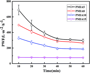
The effect of PMIA concentration on PWF is shown in Fig. 8. As shown in Fig. 8, the PWF decreased from 296.85 L m−2 h−1 for PMIA5 to 75.78 L m−2 h−1 for PMIA15 when the concentration of PMIA is increased in the doping solution. This was because the higher PMIA concentration leads to a smaller pore size and denser surface, which results in a decrease in membrane permeability. Fig. 8 also indicated that the PWF decline gradually slowed down with the increase in PMIA concentration. This was because the higher PMIA concentration promoted the resistance to the compaction of the porous membranes.48
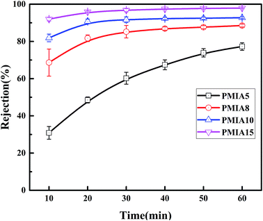
The effect of PMIA concentration on separation of BSA solution is shown in Fig. 9. As shown in Fig. 9, the rejection increased with the test time increasing, which was because the pollutant deposition leads to a cake layer on the membrane surface with the test time, finally reaching 77.3%, 88.5%, 92.7%, and 97.9% for PMIA5, PMIA8, PMIA10, and PMIA15, respectively. The rejection of PMIA5 was lower than the others due to the big pore size, as shown in Fig. 7. A high PMIA concentration in the doping solution led to a denser skin layer and smaller pore size distribution, as shown in Fig. 4 and 7. Thus, the BSA rejection increased from 77.3% to 97.9% when the PMIA concentration was increased.
Antifouling performance
In order to evaluate the antifouling performance of the BR PMIA hollow fiber membranes, the skim milk solution was diluted 50 times and then used as the filtration solution. The rejection and flux recovery of the BR PMIA hollow fiber membranes were tested. The results are shown in Fig. 10. It could be seen that the rejection of the skim milk solution reached 94.5% from Fig. 10a, which indicated that BR PMIA hollow fiber membranes had a good separation efficiency. As shown in Fig. 10b, the FRR values of PMIA10 and PMIA15 were higher than 94%, which indicated that the membranes had excellent antifouling properties for protein. The reason for this may be related to two possible factors. First, strong polar amide groups (–NH–CO–) exist in the PMIA macromolecular chain, giving the membranes strong electronegativity and excellent hydrophilicity. Second, the smaller pore size and dense outer surface would avoid the adsorption and pore blockage in the membrane's inner pores. As a result, the protein fouling mainly occurs on the membrane surface. Therefore, they could be removed easily by water.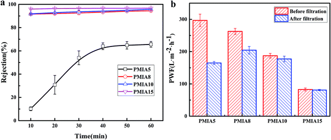 | ||
| Fig. 10 Rejection and flux recovery of the BR PMIA hollow fiber membranes in the separation process of a skim milk solution: (a) rejection, (b) the pure water flux before and after filtration. | ||
In order to further analyze the antifouling properties of BR PMIA, a simple fouling experiment with BSA solution was studied. The mean average pore size of the commercial PVDF membrane was 0.1 μm, which was close to PMIA15 (0.148 μm). Thus, both the PMIA15 and the commercial PVDF membrane were tested, respectively. The flux recovery was tested after the fouled membranes washed with deionized water. The flux recovery ratio (FRR) and total flux decline ratio (DRt) were the characteristic parameters related to the membrane antifouling property. The higher value of FRR and lower value of DRt indicated a better antifouling property of the membrane. The results are shown in Fig. 11. As shown in Fig. 11, the FRR values of PMIA15 and the commercial PVDF membrane were 96.68% and 74.23%, respectively. Simultaneously, the DRt values of PMIA15 and the commercial PVDF membrane were 35.39% and 65.11%. These results indicated that PMIA15 had better antifouling properties for protein than commercial PVDF membrane. The DRr and DRir values of PMIA15 were 32.07% and 3.32%, while those of the commercial PVDF membrane were 39.34% and 25.77%. The deposition and irreversible adsorption of BSA aggregates onto the membrane surface induced an irreversible fouling, whereas the deposition and weak interaction of BSA aggregates to the membrane surface induced a reversible fouling.39 The strong electronegativity and excellent hydrophilicity hindered the irreversible adsorption and deposition of BSA aggregates to the membrane surface and induced more deposition and a weak interaction of BSA aggregates, which enhanced the antifouling property of the membranes. As mentioned above, the PMIA membrane had a stronger electronegativity and excellent hydrophilicity compared to the PVDF membrane, so that the PMIA15 membrane had a better antifouling property than the commercial PVDF membrane.
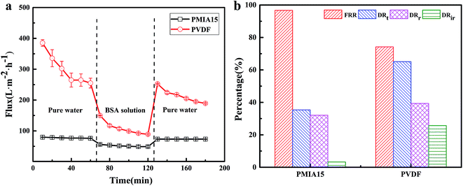 | ||
| Fig. 11 Time-dependent permeate flux of PMIA15 membranes and commercial PVDF membranes (a), and the summary of the corresponding FRR, DRt, DRr, DRir values (b) during BSA solution filtration. | ||
Mechanical properties
The mechanical properties of the BR PMIA hollow fiber membranes with various PMIA concentration are shown in Table 4. As shown in Table 4, the tensile strength and breaking elongation were close to the tensile strength of the reinforced braids, as the mechanical strength mainly depended on the reinforced braids. The tensile strength and breaking elongation of the BR PMIA hollow fiber membranes were lower than the tensile strength of the reinforced braid due to the slight dissolution of PMIA fibers in the doping solution. Moreover, the increase in the PMIA concentration in the doping solution led to the increase in the initial modulus. This was because the separation layer, which was tightly bonded with the reinforced braid of the BR PMIA hollow fiber membranes, prevented the deformation of the reinforced braid. The higher PMIA concentration in the doping solution also les to better mechanical properties of the separation layer. Besides, the bursting strength increased with the increase in PMIA concentration in the doping solution as the separation layer had a superior mechanical strength with a higher PMIA concentration. The bursting strength is a critical parameter in the backwashing process, where a superior bursting strength would limit damage to the BR PMIA hollow fiber membranes in the backwashing process.| Sample | Initial modulus (MPa) | Tensile strength (MPa) | Breaking elongation (%) | Bursting strength (MPa) |
|---|---|---|---|---|
| PMIA braid | 88.1 ± 0.81 | 193.87 ± 1.02 | 78.96 ± 0.55 | |
| PMIA5 | 312.5 ± 8.24 | 178.76 ± 2.35 | 68.2 ± 4.15 | 0.367 ± 0.029 |
| PMIA8 | 372.2 ± 6.48 | 173.15 ± 3.21 | 63.42 ± 2.79 | 0.467 ± 0.029 |
| PMIA10 | 510.1 ± 9.66 | 172.66 ± 4.65 | 63.5 ± 3.09 | 0.583 ± 0.029 |
| PMIA15 | 924.4 ± 11.1 | 179.15 ± 3.73 | 63.2 ± 3.89 | 0.983 ± 0.029 |
Thermal stability
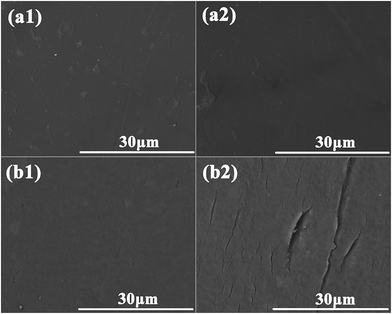
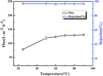
The thermal stability of the BR PMIA membranes was tested with ink solution, while the operation temperature were enhanced from 25 °C to 90 °C. The results are shown in Fig. 12. It could be seen that when the operation temperature changed from 25 °C to 90 °C, the water flux increased more than two-fold with the stable ink solution rejection of the PMIA15 membrane, while the ink solution rejection of the PVDF membrane was reduced dramatically. For the water solution, the viscosity coefficients decreased while the diffusion coefficients increased with the increasing temperature.18,19 So the water flux increased with the operation temperature changing from 25 °C to 90 °C. Fig. 13 shows the outer surface morphologies of the PMIA15 and commercial PVDF membranes following the thermal rejection process. As shown in Fig. 13, the outer surface of the commercial PVDF membrane undergoes a serious cracking phenomenon, while there was no obvious difference in the PMIA membrane when the operation temperature was 90 °C. This could be the main reason for the ink solution rejection of the PVDF membrane being reduced dramatically when the operation temperature ranged from 25 °C to 90 °C. The plentiful benzene rings and intermolecular hydrogen bonding in the PMIA macromolecular chains leads the glass transition temperature of PMIA to be more than 270 °C, which would prevent the pore structure from undergoing deformation in thermal conditions. This indicated that the BR PMIA hollow fiber membranes had excellent thermal stability and exhibited great potential for application in high temperature separation processes.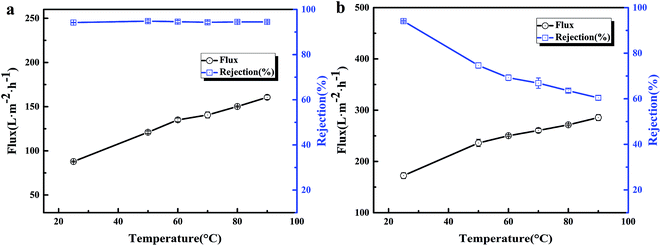 | ||
| Fig. 12 The flux and rejection of the BR PMIA hollow fiber membranes at different temperatures for: (a) the BR PMIA membranes, (b) the commercial PVDF membranes. | ||
In order to further analyze the thermal stability of the BR PMIA hollow fiber membranes, the PMIA hollow fiber membranes fabricated via a phase invasion method without braid reinforcement were applied to compare the thermal stability with the BR PMIA hollow fiber membranes. The compositions of the doping solution of the PMIA hollow fiber membrane were identical with that of PMIA15. As shown in Fig. 14, the flux of the PMIA hollow fiber membranes increased while the rejection remained stable when the operation temperature ranged from 25 °C to 90 °C. This indicated that the PMIA hollow fiber membranes also had a better thermal stability. However, the flux of the PMIA hollow fiber membranes was lower than that of the BR PMIA hollow fiber membranes. As shown in Fig. S9,† both the BR PMIA hollow fiber membranes and PMIA hollow fiber membranes had a dense outer layer, while the BR PMIA hollow fiber membranes had a relatively porous inner layer compared with the PMIA hollow fiber membranes. This should result in a lower mass transfer resistance of BR PMIA hollow fiber membranes; therefore, the BR PMIA hollow fiber membranes had a superior flux than the PMIA hollow fiber membranes. As a consequence, the BR PMIA hollow fiber membranes may be a better choice compared with PMIA hollow fiber membranes.
Conclusion
The dry–wet spinning process was applied to fabricate BR PMIA hollow fiber membranes consisting of a separation layer and reinforced braids. The increase in PMIA concentration in the doping solution led to a decrease in the PWF and pore size, and an increase in the rejection of BSA. The high FRR and low DRt indicated that the BR PMIA membranes had an excellent antifouling property. The tensile strength of the BR PMIA membranes exceeded 170 MPa. Moreover, the BR PMIA membranes had a favorable interfacial bonding force between the separation layer and reinforced braids. This indicated that the BR PMIA membranes had a good mechanical property. When the operating temperature changed from 25 °C to 90 °C, the water flux increased more than two-fold with stable ink solution rejection, which proved the excellent thermal stability and exhibited a great potential for application in high temperature separation processes.Acknowledgements
The authors gratefully acknowledge the financial support of the National Natural Science Foundation of China (21274109, 51603146) and the National Basic Research Program of China (973 Program, 2012CB722706).References
- S. I. Patsios and A. J. Karabelas, J. Membr. Sci., 2011, 372, 102–115 CrossRef CAS.
- T. Buer and J. Cumin, Desalination, 2010, 250, 1073–1077 CrossRef CAS.
- S. Chang, Desalination, 2011, 283, 31–39 CrossRef CAS.
- M. Hashino, T. Katagiri, N. Kubota, Y. Ohmukai, T. Maruyama and H. Matsuyama, J. Membr. Sci., 2011, 366, 389–397 CrossRef CAS.
- P. Cote, Z. Alam and J. Penny, Desalination, 2012, 288, 145–151 CrossRef CAS.
- X. Hu, Y. Chen, H. Liang and C. Xiao, Mater. Sci. Technol., 2011, 27, 661–665 CrossRef CAS.
- X. Zhang, C. Xiao, X. Hu and Q. Bai, Appl. Surf. Sci., 2013, 264, 801–810 CrossRef CAS.
- M. Mahendran, K. P. Goodboy and L. Fabbricino, U.S. Pat., 6354444, 2002.
- M. Mailvaganam, L. Fabbricino, C. F. F. Rodrigues and A. R. Donnelly, U.S. Pat., 5472607, 1995.
- M. S. Lee, S. H. Choi and Y. C. Shin, U.S. Pat., 7267872B2, 2007.
- J. Hao, C. Xiao, T. Zhang, J. Zhao, Z. Fan and L. Chen, Ind. Eng. Chem. Res., 2016, 55, 2174–2182 CrossRef CAS.
- Z. Fan, C. Xiao, H. Liu, Q. Huang and J. Zhao, J. Membr. Sci., 2015, 486, 248–256 CrossRef CAS.
- Z. Fan, C. Xiao, H. Liu and Q. Huang, Cellulose, 2015, 22, 695–707 CrossRef CAS.
- H. Liu, C. Xiao, Q. Huang and X. Hu, Desalination, 2013, 331, 35–45 CrossRef CAS.
- H. Liu, C. Xiao, Q. Huang, X. Hu and W. Shu, J. Membr. Sci., 2014, 472, 210–221 CrossRef CAS.
- X. Zhang, C. Xiao, X. Hu, X. Jin and Q. Bai, Desalination, 2013, 330, 49–60 CrossRef CAS.
- R. Han, S. Zhang, L. Hu, S. Guan and X. Jian, J. Membr. Sci., 2011, 370, 91–96 CrossRef CAS.
- K. Y. Wang, T.-S. Chung and J.-J. Qin, J. Membr. Sci., 2007, 300, 6–12 CrossRef CAS.
- K. Y. Wang, Q. Yang, T.-S. Chung and R. Rajagopalan, Chem. Eng. Sci., 2009, 64, 1577–1584 CrossRef CAS.
- S. Zhao, P. Wang, C. Wang, X. Sun and L. Zhang, Desalination, 2012, 299, 35–43 CrossRef CAS.
- S. Zhao, P. Wang, C. Wang, J. L. Langer, G. Abulikemu and X. Sun, Chem. Eng. J., 2013, 219, 419–428 CrossRef CAS.
- J. Han, D. Yang, S. Zhang, L. Wang and X. Jian, Desalination, 2014, 350, 95–101 CrossRef CAS.
- L. Hu, S. Zhang, R. Han and X. Jian, Appl. Surf. Sci., 2012, 258, 9047–9053 CrossRef CAS.
- C. Wu, S. Zhang, D. Yang and X. Jian, J. Membr. Sci., 2009, 326, 429–434 CrossRef CAS.
- C. Ba and J. Economy, J. Membr. Sci., 2010, 363, 140–148 CrossRef CAS.
- S. Jiang, H. Zhang, S. Song, Y. Ma, J. Li, G. H. Lee, Q. Han and J. Liu, ACS Nano, 2015, 9, 10252–10257 CrossRef CAS PubMed.
- K. Chen, S. Zhang, B. Liu, X. Mao, G. Sun, J. Yu, S. S. Al-Deyab and B. Ding, RSC Adv., 2014, 4, 45760–45767 RSC.
- X. Wang, Y. Si, X. Wang, J. Yang, B. Ding, L. Chen, Z. Hu and J. Yu, Nanoscale, 2013, 5, 886–889 RSC.
- X. Tang, Y. Si, J. Ge, B. Ding, L. Liu, G. Zheng, W. Luo and J. Yu, Nanoscale, 2013, 5, 11657–11664 RSC.
- Y. Zhai, N. Wang, X. Mao, Y. Si, J. Yu, S. S. Al-Deyab, M. El-Newehy and B. Ding, J. Mater. Chem. A, 2014, 2, 14511–14518 CAS.
- K. Xiao, Y. Zhai, J. Yu and B. Ding, RSC Adv., 2015, 5, 55478–55485 RSC.
- X. Ren, C. Zhao, S. Du, T. Wang, Z. Luan, J. Wang and D. Hou, J. Environ. Sci., 2010, 22, 1335–1341 CrossRef CAS.
- J. Huang and K. Zhang, Desalination, 2011, 282, 19–26 CrossRef CAS.
- T. Wang, C. Zhao, P. Li, Y. Li and J. Wang, Desalination, 2015, 365, 293–307 CrossRef CAS.
- T. Wang, C. Zhao, P. Li, Y. Li and J. Wang, J. Membr. Sci., 2015, 477, 74–85 CrossRef CAS.
- M. Yang, C. Zhao, S. Zhang, P. Li and D. Hou, Appl. Surf. Sci., 2017, 394, 149–159 CrossRef CAS.
- C.-E. Lin, J. Wang, M.-Y. Zhou, B.-K. Zhu, L.-P. Zhu and C.-J. Gao, J. Membr. Sci., 2016, 518, 72–78 CrossRef CAS.
- X. Zhao, Y. Su, W. Chen, J. Peng and Z. Jiang, J. Membr. Sci., 2012, 415–416, 824–834 CrossRef CAS.
- X. Fan, Y. Su, X. Zhao, Y. Li, R. Zhang, J. Zhao, Z. Jiang, J. Zhu, Y. Ma and Y. Liu, J. Membr. Sci., 2014, 464, 100–109 CrossRef CAS.
- J. Zhang, Z. Xu, W. Mai, C. Min, B. Zhou, M. Shan, Y. Li, C. Yang, Z. Wang and X. Qian, J. Mater. Chem. A, 2013, 1, 3101–3111 CAS.
- M. C. García-Payo, M. Essalhi and M. Khayet, J. Membr. Sci., 2010, 347, 209–219 CrossRef.
- M. C. García-Payo, M. Essalhi and M. Khayet, Desalination, 2009, 245, 469–473 CrossRef.
- A. K. Hołda, B. Aernouts, W. Saeys and I. F. J. Vankelecom, J. Membr. Sci., 2013, 442, 196–205 CrossRef.
- A. J. Reuvers and C. A. Smolders, J. Membr. Sci., 1987, 34, 67–86 CrossRef CAS.
- C. A. Smolders, A. J. Reuvers, R. M. Boom and I. M. Wienk, J. Membr. Sci., 1992, 73, 259–275 CrossRef CAS.
- L. Yao, C. Lee and J. Kim, Fibers Polym., 2010, 11, 1032–1040 CrossRef CAS.
- Y. Liao, T. P. Farrell, G. R. Guillen, M. Li, J. A. T. Temple, X.-G. Li, E. M. V. Hoek and R. B. Kaner, Mater. Horiz., 2014, 1, 58–64 RSC.
- J. Liu, P. Li, Y. Li, L. Xie, S. Wang and Z. Wang, Desalination, 2009, 249, 453–457 CrossRef CAS.
Footnote |
| † Electronic supplementary information (ESI) available. See DOI: 10.1039/c7ra01171g |
| This journal is © The Royal Society of Chemistry 2017 |


