 Open Access Article
Creative Commons Attribution 3.0 Unported Licence
ZnO nanosheet-assisted immobilization of Ag nanoparticles on graphene/Ni foam for highly efficient reduction of 4-nitrophenol
Y. Y. Liu ab,
X. L. Guo*ab,
L. Zhua,
X. J. Wanga,
C. Gea,
L. Zhaoa,
J. Chena,
Y. Zhanga,
Z. M. Wanga and
L. T. Sun
 bc
bc
aJiangsu Key Laboratory of Advanced Metallic Materials, School of Materials Science and Engineering, Southeast University, Nanjing 211189, China. E-mail: guo.xinli@seu.edu.cn
bSEU-JSRI Joint Research Center for the Application of Advanced Carbon Materials, Nanjing 210096, China
cThe Key MEMS Lab, School Electronics Science and Engineering, Southeast University, Nanjing 210096, China
First published on 17th March 2017
Abstract
The excellent catalytic properties of silver (Ag) nanoparticles (AgNPs) are generally deteriorated during use because of their irreversible agglomeration and the surfactants coating them. In this research, a novel hybrid structure of as-synthesized silver nanoparticles/zinc oxide nanosheets/graphene/nickel foam (AgNPs/ZnO/Gr/NiF) was prepared using chemical vapor deposition (CVD) combined with a hydrothermal reaction and in situ reduction with ascorbic acid. The as-prepared AgNPs/ZnO/Gr/NiF hybrid structure was characterized using Raman spectrometry, scanning electron microscopy, and X-ray diffraction. The ZnO nanosheets were identified as an effective buffer layer to improve the homogeneity and stability of the as-synthesized AgNPs on the surface of Gr/NiF hybrid structure because of its assisted role in carrying and immobilizing the AgNPs to the surface of Gr/NiF via chelation and complexation of arginine to both ZnO and Ag ions during the in situ reduction process of Ag ions. The as-prepared AgNPs/ZnO/Gr/NiF hybrid structure is flexible and exhibits high efficiency and recyclability for the reduction of 4-nitrophenol to 4-aminophenol.
1 Introduction
Silver nanoparticles (AgNPs) have attracted particular interest in catalytic applications because of their high surface areas and versatile catalytic activities.1–6 However, AgNPs prepared using chemical methods cannot contact with the reactants effectively because of the surfactants coating them.7–10 In addition, AgNPs may produce irreversible conglomeration after a long time being laid to one side. Therefore, finding the proper base materials to stably and homogeneously disperse AgNPs is significant and the solution to the problem will be of great value.Recently, graphene (Gr; a two-dimensional (2D) material) has been widely researched because of its unique electrical, optical and chemical properties such as high conductivity, high specific surface area, excellent chemical stability, and so on, which makes it a promising base material. Furthermore, three-dimensional graphene (3D graphene) constructed using a 2D graphene nanosheets has a porous structure and much higher specific surface area than 2D graphene. In particular, 3D graphene prepared using chemical vapor deposition (CVD) has a higher purity and conductivity. Therefore, it should be more suitable for use as a base material for preparing metal nanoparticles. Up to the present time, most of the research on metal nanoparticles/graphene hybrid nano-structures for a variety of catalytic reactions, such as copper (Cu),11 silver (Ag),12,13 gold (Au),14–22 Ag–Au,23,24 platinum (Pt),25–28 molybdenum disulfide (MoS2),29 silver iodide (AgI),30 zinc oxide (ZnO)31–33 have been focused on metal nanoparticles/graphene sheets or metal nanoparticles/graphene aerogel. However, the metal nanoparticle/graphene sheet composites have poor stability and low recyclability. For metal nanoparticle/graphene aerogel hybrids, the aerogel may strongly limit the activity of the nanoparticles because of its hydrophobicity.
AgNPs can be attached on to the surface of ZnO.34–39 The nano-ZnO modified with AgNPs or the Ag/ZnO nanostructure hybrid have been widely studied for their use in antibacterial materials, the removal of heavy metal ions, photo-catalysis, biological sensors and other fields. From the point of view of immobilization, Ag ions can readily self-assemble on the ZnO surface as they provide both anchoring sites for the metal ions to bind and nucleation sites for their subsequent growth.40–42 Therefore, ZnO can be used as a middle carrier between AgNPs and 3D graphene. The 3D graphene is decorated with a layer of ZnO film, and then the Ag ions are bound and reduced in situ on the surface of the ZnO films, thus, forming a uniform layer of AgNPs on the surface of the 3D graphene.
4-Nitrophenol (4-NP) is a pollutant which often exists in industrial and agricultural waste waters. So it is necessary to remove it from polluted waters to meet increasingly stringent environmental quality standards. As usual, the reduction of 4-NP to 4-aminophenol (4-AP) is the best method for removing the toxic 4-NP. Nevertheless, the reduction is only possible in the presence of a catalyst and therefore it is also usually selected as model reaction to check the catalytic activity of various catalysts.
In this research, graphene/nickel foam (Gr/NiF) was prepared using CVD. The Gr/NiF, without removing the Ni foam substrate, was used as the substrate to prepare ZnO/Gr/NiF using a simple in situ precipitation process under hydrothermal conditions. The AgNPs were attached on the surface of ZnO/Gr/NiF using an in situ reduction method with ascorbic acid, thus, forming a novel hybrid AgNP/ZnO/Gr/NiF. The as-prepared AgNP/ZnO/Gr/NiF hybrid structure exhibited a high reduction efficiency for the reduction of 4-NP to 4-AP and showed high recyclability and flexibility.
2 Experimental
2.1 Materials and reagents
Zinc chloride (ZnCl2, ≥98.0% pure), ammonia solution (NH3, 25–28%), silver nitrate (AgNO3, ≥99.8% pure), arginine (C6H14N4O2, ≥98.0% pure), sodium hydroxide (NaOH, ≥96.0% pure), ascorbic acid (C6H8O6, ≥99.7% pure), 4-NP (C6H5NO3, ≥99.0% pure), and sodium borohydride (NaBH4, ≥96.0% pure) were used for this experimental work. The 4-nitrophenol was stored at −3 °C.2.2 Preparation of Gr/NiF
Gr/NiF was prepared using a CVD method. Methane (CH4) was used as the carbon (C) source. The Ni foams of size 0.16 cm × 2.0 cm × 3.0 cm were cleaned first using ethanol and then acetone. The NiF was loaded into a quartz tube and exposed to an environment of hydrogen (H2, 100 sccm) and argon (100 sccm) and the temperature was raised to 1000 °C. Then the quartz tube was held at 1000 °C for 30 min and CH4 (10 sccm) and H2 (100 sccm) were introduced into the quartz tube and held for 5 min.2.3 Preparation of ZnO nanosheet/Gr/NiF hybrid
The ZnO nanosheet/Gr/NiF hybrids were prepared from ZnCl2 in alkaline solution in a hydrothermal environment.43 In detail, 0.05 mol ZnCl2 and 2 ml NH3 were dissolved in 40 ml of deionized water and stirred thoroughly. Then, the Gr/NiF was immersed in the solution and subjected to hydrothermal treatments at 120 °C for 90 min in an autoclave. The ZnO/Gr/NiF hybrids were obtained after washing and drying at room temperature.2.4 Preparation of AgNP/ZnO/Gr/NiF hybrid
An aqueous solution of arginine–silver complexes was prepared using the following process.44 AgNO3 (1 mmol) was dispersed in 30 ml of deionized water and 0.4 mmol arginine was dispersed in 20 ml of deionized water (adjusted to pH 11 by adding NaOH). After the solid had dissolved adequately, the arginine solution was added dropwise into the AgNO3 solution, and a small amount of white precipitate was produced. Then, the ZnO/Gr/NiF hybrid was immersed in an arginine–silver solution for six hours. The above product was cleaned by ultrasound in water and dried. Finally, the sample was dipped into a solution of ascorbic acid (50 ml, 100 mM) for 30 min.2.5 Reduction of 4-NP catalyzed using the AgNPs/ZnO/Gr/NiF hybrid
Solutions of 4-NP (0.05 mM) and NaBH4 (0.1 M) were freshly prepared. Then, 2 ml of 4-NP was mixed with 1 ml of iced NaBH4 in a bottle, and the color of the mixed solution became yellow. The AgNP/ZnO/Gr/NiF hybrid (1 × 1 × 0.16 cm3) was then immersed in the yellow cultured mixed solution obtained previously. At 30 s intervals, the AgNP/ZnO/Gr/NiF was removed and the remaining mixed solution was transferred to a quartz cuvette for measurement using ultraviolet-visible (UV-vis) spectroscopy. The solution was transferred back to the bottle for a sequential reaction for the next 30 s. The catalytic reaction lasted for 180 s and the solution become transparent in color. With the increase of time, the absorption peak of the 4-NP ion at 400 nm gradually decreased while a new peak appeared at 300 nm, suggesting that the 4-NP had decomposed and that the 4-AP had been generated.2.6 Characterization and measurement
Raman spectra were measured using a Raman spectrometer (Thermo Fisher Scientific) in the range of 200–4000 cm−1. Scanning electron microscopy (SEM) and energy dispersive X-ray (EDX) spectroscopy measurements were performed on a Quanta 200 scanning microscope (FEI) with 10 kV acceleration voltage. X-ray diffraction (XRD) spectra were obtained using a D8-DISCOVER X-ray diffractometer (Bruker) with scanning in the range of 2θ = 20–80°. UV-vis spectra were measured using a UV-2450 spectrophotometer (Shimadzu) with 1 cm × 1 cm × 3 cm quartz cells in the range of 200–500 nm.3 Results and discussion
The morphology of the as-prepared Gr/NiF and ZnO/Gr/NiF hybrids with different magnifications are shown in Fig. 1. Fig. 1a shows the porous morphology of Gr/NiF. The graphene has grown homogeneously on the surface of the Ni foam with a thickness ∼3–6 layers. After synthesis of the ZnO nanosheet on the surface of the porous Gr/NiF, the surface becomes relatively rough with a large number of nanosheets (white area) uniformly distributed on the surface, see Fig. 1b–d. The inset in Fig. 1d shows the typical morphology of the ZnO nanosheet at a higher magnification. The thickness of the ZnO films is about 19 nm and the length is about 5 μm. The large specific surface area of ZnO nanosheet provides plentiful sites for the deposition of AgNPs.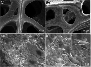 | ||
| Fig. 1 (a) SEM image of Gr/NiF. (b–d) SEM images of ZnO/Gr/NiF at different magnifications. The inset of (d) shows the morphology of the ZnO nanosheet at high magnification. | ||
Fig. 2a–c show the morphology of the AgNP/ZnO/Gr/NiF hybrid at different magnifications. It can be observed that the AgNPs are homogeneously distributed on the surface of the ZnO/Gr/NiF hybrid. The particle size distribution is shown in Fig. 2d and the mean diameter of the AgNPs is 134.8 nm. Fig. 2e shows the EDX spectrum of the AgNP/ZnO/Gr/NiF hybrid, which shows the presence of the elements: Ni, C and Ag and indicates that Ag particles are attached in the ZnO nanosheet. Based on the distribution of the elements shown in the table inset in Fig. 2e, the weight percentage and the atomic percentage of Ag particles are calculated to be ∼33.46 and 13.78, respectively.
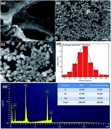 | ||
| Fig. 2 (a–c) SEM images of AgNP/ZnO/Gr/NiF hybrids at different magnifications. (d) Particle size distribution of the Ag particles. (e) EDX spectrum of AgNP/ZnO/Gr/NiF. | ||
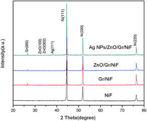
The XRD spectra of NiF, Gr/NiF, ZnO/Gr/NiF and the AgNP/ZnO/Gr/NiF hybrid are shown in Fig. 3. The peaks at 2θ of 44.5°, 51.88° and 76.43° are assigned as the (111), (200) and (220) planes of the face centered cubic Ni. The Gr/NiF shows one more diffraction peak than NiF at 2θ of 26.5°, which is attributed to the (002) reflection of graphitic carbon. The diffraction peak of ZnO appears unobvious because of the particularly strong peaks of Ni. In addition, the AgNP/ZnO/Gr/NiF presents one more diffraction peak than ZnO/Gr/NiF at 38.5°, indicating the (111) planes of the face centered cubic Ag.
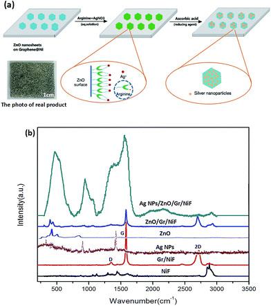
The effect of the ZnO nanosheet and the preparation mechanism of AgNP/ZnO/Gr/NiF hybrid are shown schematically in Fig. 4a. As shown in Fig. 4a, the ZnO nanosheet can be used as a middle carrier to realize the connection of the AgNPs and 3D graphene using the following process: (1) when ZnO is exposed to ambient air or in water, the hydroxyl groups will be formed on the surface of the ZnO. These hydroxyl groups act as active sites for the adsorption of cations, which is the same as the mechanism of ZnO for removing heavy metal ions.45–47 Therefore, Ag+ can be directly deposited and reduced on the surface of the ZnO nanosheet. However, in the absence of binder, it is difficult to control the size and distribution of AgNPs on the surface of ZnO. (2) In order to realize the connection of AgNPs and ZnO, the arginine a type of amino acid is used.42 The high isoelectric point (IEP) of ZnO (9.5) makes it feasible to immobilize the low IEP of materials such as protein and amino acids using electrostatic adsorption.48 Arginine has previously been known to be involved in the surface modification of ZnO as a ZnO-binding polypeptide. In addition, arginine will bind Ag ions via chelation and complexation mechanisms under alkaline conditions, forming stable silver–arginine complexes. The silver–arginine may exist as the tridentate structure that is showed in the dotted circle on the left. In this way, more Ag+ can easily bind on ZnO films with the help of arginine. (3) The silver–arginine tridentate complexes self-assembled onto the ZnO films are reduced by ascorbic acid. In addition, ZnO exposed to light, especially UV light can produce free negative electrons, which promote the reduction of Ag+. Therefore, the AgNPs are fastened to ZnO nanosheets, which are bound on to the 3D graphene. Furthermore, the photograph of the real product shows that it is flexible and its structure is solid.
Fig. 4b shows the Raman spectra of NiF, Gr/NiF, AgNPs, ZnO, ZnO/Gr/NiF and the AgNP/ZnO/Gr/NiF hybrid. The Raman spectrum of NiF shows a sharp peak at ∼2900 cm−1. In contrast, the Gr/NiF presents three peaks at ∼1350, ∼1570 and ∼2700 cm−1, indicating the characteristic D, G and 2D bands of graphene, respectively. The Raman spectrum of pure ZnO exhibits one prominent peak at ∼424 cm−1. The ZnO/Gr/NiF shows superposed peaks of graphene and ZnO. The AgNPs have two outstanding peaks at ∼1074 cm−1 and ∼1583 cm−1. The AgNP/ZnO/Gr/NiF hybrid presents additive peaks of all materials, indicating the successful preparation of the AgNP/ZnO/Gr/NiF hybrid. Furthermore, the Raman intensity for the AgNP/ZnO/Gr/NiF is much higher than that collected for the pure AgNPs substrate. The reason attributed for this is that the ZnO-coated Gr/NiF hybrids provide a larger active surface on which to deposit more AgNPs.
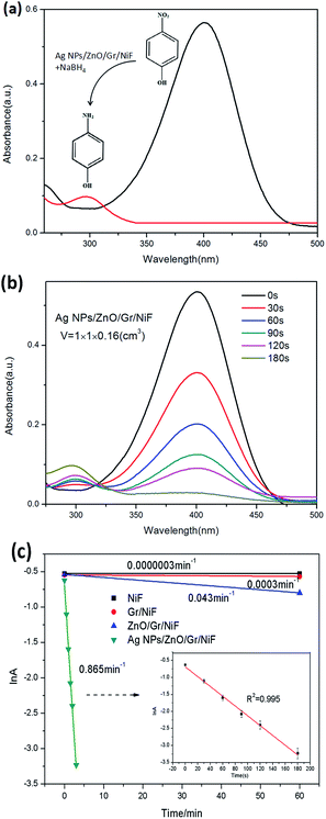
The catalytic reduction of 4-NP to 4-AP with an excess of NaBH4 has often been used as a model reaction to evaluate the catalytic performance of metal nanoparticles. UV-vis spectrometry is used for real-time monitoring of the reaction process. As illustrated in Fig. 5a, the solution of 4-NP in water shows a peak at about 400 nm whereas the 4-AP exhibits a peak at about 300 nm. In general, the absorbance at 400 nm remained unchanged with time for as long as two days without the addition of any other catalyst. As can be seen from the chemical formulae, the 4-NP is converted into 4-AP because of the exchange of O, H elements between 4-NP and 4-AP, respectively. With the addition of the AgNP/ZnO/Gr/NiF hybrid (1 × 1 × 0.16 cm3) catalyst, the reduction reaction is significantly increased. With the increase of time, the typical absorption peak of the 4-NP ion at 400 nm gradually decreased while a new peak at about 300 nm appeared, suggesting that the 4-NP has decomposed and the 4-AP had been generated (Fig. 5b). The reduction reaction lasted for 180 s and the peak at 400 nm disappeared. Fig. 5c shows a linear correlation between ln(A) (where A is the absorbance at 400 nm) versus the reduction time of NiF, Gr/NiF, ZnO/Gr/NiF and AgNP/ZnO/Gr/NiF hybrid. The NiF and Gr/NiF hardly seem to have generated any catalytic effect. The ZnO/Gr/NiF slightly accelerated the reaction, which resulted from the ZnO nanosheets producing a slight photocatalytic effect under the visible light irradiation. By contrast, the AgNP/ZnO/Gr/NiF hybrid showed a significant catalytic effect. The inset of Fig. 5c is the enlarged drawing (with error bars) of the reaction with the AgNP/ZnO/Gr/NiF hybrid. It shows a good linear relationship and the R2 = 0.995 which indicates that the reaction is pseudo first-order. The rate constant (K) determined from the slope is 0.865 min−1, which is higher than that obtained using other catalysts (Table 1). The ratio of the rate constant K over the macroscopic volume of the AgNPs/ZnO/Gr/NiF, was calculated using activity (k) = K/V. The activity k of the AgNP/ZnO/Gr/NiF is k = 0.865 min−1/(1 × 1 × 0.16 cm3) = 5.406 min−1 cm−3.
| Catalyst | Supported material | Concentration of 4-NP (mM) [mmol] | Concentration of NaBH4 (mM) [mmol] | K (min−1) | Ref. |
|---|---|---|---|---|---|
| AgNPs | No | 0.1 [3 × 10⁻⁴] | 100 [3 × 10⁻²] | 0.191 | 7 |
| AgNPs | No | 5 [2.5 × 10⁻⁵] | 100 [0.25] | 0.111 | 2 |
| Ag@MWCNTs | Carbon nanotubes | 0.1 [1.5 × 10⁻³] | 5 [7.5 × 10⁻²] | 0.4728 | 4 |
| AgNPs/CNFs | CNFs | 0.12 [3.6 × 10⁻³] | 5 [0.15] | 0.372 | 1 |
| Au/Tween/GO | GO | 7 [7 × 10⁻³] | 0.16 [1.6 × 10⁻⁴] | 0.2537 | 15 |
| Graphene/PDA–Au | GO | 1 [1 × 10⁻³] | 330 [1.32] | 0.38 | 18 |
| Pt@3DG | 3D-graphene | 0.033 [1.98 × 10⁻⁴] | 0.4 [5.6 × 10⁻³] | 0.389 | 26 |
| 3DG@Au NSs | 3D-graphene (CVD) | 10 [1 × 10⁻²] | 10 [2 × 10⁻²] | 0.3798 | 19 |
| Au/graphene | 3D-graphene | 0.1 [2.8 × 10⁻⁴] | 100 [2 × 10⁻²] | 0.19 | 21 |
| Ag/ZnO/Gr/NiF | 3D-graphene/NiF (CVD) | 0.05 [1 × 10⁻⁴] | 100 [0.1] | 0.865 | This work |
In order to compare the differences found between this catalyst and others report in papers found in the literature, the results were tabulated in Table 1. By contrast, it can be seen that there several advantages to using the catalyst prepared in the present research. The 3D-graphene was prepared using CVD without removing the NiF substrates. In this way, graphene was obtained not only with high purity but also with high conductivity, and also the 3D-graphene has a high mechanical strength. Then, the as-prepared graphene/NiF was made into the supporting material. Using the “ZnO nanosheet-assisted” method, the AgNPs were attached on to the surface of the base substrates using an in situ reduction method without adding any surfactant. At the same time, the problems of uneven dispersion and weak connection of nanoparticles will not exist in this catalyst. From the previous points, it can be seen that the high activity can be attributed to the following reasons: (1) a larger amount of AgNPs are uniformly bound onto the Gr/NiF covering with the ZnO nanosheets, thus, improving the hydrophobicity of the Gr/NiF. Thus, the reaction solution can more easily penetrate into the pores, accelerating the process of catalysis. (2) Uncoated AgNPs can be fully exposed to its active sites, providing a number of places for swapping elements. (3) AgNPs and Gr/NiF all have exceptional conductivity and stability, which speeds up the electron transfer.
Fig. 6 shows the mechanism of 4-NP molecule reduction using the AgNP/ZnO/Gr/NiF hybrid in the presence of NaBH4 in aqueous medium. The catalytic process mainly consists of three parts: (1) the BH4− and 4-NP absorb on the AgNPs together. (2) Then, BH4− and 4-NP start electron transfer and atomic exchange. In detail, the BH4− ions lose their electrons and hydrogen atoms while the 4-NP obtains electrons and hydrogen atoms while losing oxygen atoms. Subsequently, the new material of 4-AP is generated. (3) The 4-AP generated automatically breaks from the AgNPs and moves in to the solution. In this process, the AgNPs show a high level of catalysis for the reaction by the way in which they provide many reaction sites and reduce the reaction kinetics of the barrier.
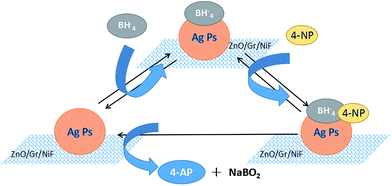 | ||
| Fig. 6 Schematic showing the 4-NP molecule reduction using the AgNP/ZnO/Gr/NiF hybrid in the presence of NaBH4 in aqueous medium. | ||
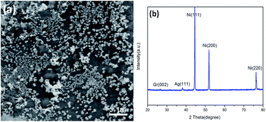
It is worth noting that the structure of the AgNP/ZnO/Gr/NiF hybrid is very stable after testing the catalytic reaction. The AgNPs maintained the same size distribution and were evenly bound on the ZnO nanosheet modified on the surface of Gr/NiF, see Fig. 7a. The XRD pattern shows that the metallic state of the AgNPs is also stable after the catalytic reaction, see Fig. 7b.
4 Conclusions
In summary, ZnO nanosheet-assisted immobilization of AgNPs on Gr/NiF was used to prepare new hybrid catalysts without any surfactant on the AgNPs. The ZnO nanosheets were identified as an effective buffer layer to improve the homogeneity and stability of the as-synthesized AgNPs on the surface of the AgNP/Gr/NiF hybrid structure. This was because of its role assisting in carrying and immobilizing the AgNPs on the surface of Gr/NiF via chelation and complexation of arginine to both ZnO and Ag ions during the in situ reduction process of Ag ions. The as-prepared AgNP/ZnO/Gr/NiF hybrid structure is flexible and exhibits high efficiency and recyclability for the reduction of 4-NP to 4-AP.Acknowledgements
The authors would like to thank the following for their financial support: the National Natural Science Foundation of China [21173041] and the 2016 Graduate Student Innovation Program of Jiangsu, China [KYLX16_0196], the Opening Project of SEU-JSRI Joint Research Center for the Application of Advanced Carbon Materials and the Opening Project of Jiangsu Key Laboratory of Advanced Metallic Materials.References
- P. Zhang, C. Shao, Z. Zhang, M. Zhang, J. Mu, Z. Guo and Y. Liu, Nanoscale, 2011, 3, 3357 Search PubMed.
- M. Bano, D. Ahirwar, M. Thomas, G. A. Naikoo, M. U. Sheikh and F. Khan, New J. Chem., 2016, 40, 6787–6795 RSC.
- A. Rostami-Vartooni, M. Nasrollahzadeh and M. Alizadeh, J. Alloys Compd., 2016, 680, 309–314 CrossRef CAS.
- S. M. Alshehri, T. Almuqati, N. Almuqati, E. Al-Farraj, N. Alhokbany and T. Ahamad, Carbohydr. Polym., 2016, 151, 135–143 CrossRef CAS PubMed.
- W. Zhou, Y. Zhou, Y. Liang, X. Feng and H. Zhou, RSC Adv., 2015, 5, 50505–50511 RSC.
- J. Qu, C. Ren, Y. Dong, Y. Chang, M. Zhou and X. Chen, Chem. Eng. J., 2012, 211–212, 412–420 CrossRef CAS.
- S. Jana, S. Ghosh, S. Nath, S. Pande, S. Praharaj, S. Panigrahi, S. Basu, T. Endo and T. Pal, Appl. Catal., A, 2006, 313, 41–48 CrossRef CAS.
- B. Ajitha, Y. A. K. Reddy, P. S. Reddy, Y. Suneetha, H. Jeon and C. W. Ahn, J. Mol. Liq., 2016, 219, 474–481 CrossRef CAS.
- X. Chen, Z. Wang, S. Bi, K. Li, R. Du, C. Wu and L. Chen, Chem. Eng. J., 2016, 295, 518–529 CrossRef CAS.
- C. Kästner and A. F. Thünemann, Langmuir, 2016, 32, 7383–7391 CrossRef PubMed.
- T. Wu, M. Chen, L. Zhang, X. Xu, Y. Liu, J. Yan, W. Wang and J. Gao, J. Mater. Chem. A, 2013, 1, 7612 CAS.
- J. Qu, C. Ren, Y. Dong, Y. Chang, M. Zhou and X. Chen, Chem. Eng. J., 2012, 211–212, 412–420 CrossRef CAS.
- Y. Tian, Y. Cao, F. Pang, G. Chen and X. Zhang, RSC Adv., 2014, 4, 43204–43211 Search PubMed.
- A. Chen, J. Qi, Q. Zhao, Y. Li, G. Zhang, F. Zhang and X. Fan, RSC Adv., 2013, 3, 8973 RSC.
- W. Lu, R. Ning, X. Qin, Y. Zhang, G. Chang, S. Liu, Y. Luo and X. Sun, J. Hazard. Mater., 2011, 197, 320–326 CrossRef CAS PubMed.
- H. Yao, T. Huang and H. Sue, RSC Adv., 2014, 4, 61823–61830 RSC.
- X. Cao, S. Yan, F. Hu, J. Wang, Y. Wan, B. Sun and Z. Xiao, RSC Adv., 2016, 6, 64028–64038 RSC.
- J. Luo, N. Zhang, R. Liu and X. Liu, RSC Adv., 2014, 4, 64816–64824 RSC.
- Z. Ma, Y. Qiu, Y. Huang, F. Gao and P. Hu, RSC Adv., 2015, 5, 79456–79462 RSC.
- F. Yang, C. Wang, L. Wang, C. Liu, A. Feng, X. Liu, C. Chi, X. Jia, L. Zhang and Y. Li, RSC Adv., 2015, 5, 37710–37715 RSC.
- J. Li, C. Liu and Y. Liu, J. Mater. Chem., 2012, 22, 8426 RSC.
- D. S. J. F. Wenjun Liu, RSC Adv., 2014, 4, 11003–11011 RSC.
- B. Neppolian, C. Wang and M. Ashokkumar, Ultrason. Sonochem., 2014, 21, 1948–1953 CrossRef CAS PubMed.
- H. Chen, X. Fan, J. Ma, G. Zhang, F. Zhang and Y. Li, Ind. Eng. Chem. Res., 2014, 53, 17976–17980 CrossRef CAS.
- R. Krishna, D. M. Fernandes, V. F. Domingos, E. S. Ribeiro, J. C. Gil, C. Dias, J. Ventura, C. Freire and E. Titus, RSC Adv., 2015, 5, 60658–60666 RSC.
- P. Zou, M. Wang, L. Zhao, L. Dai and Y. Wang, Appl. Organomet. Chem., 2016, 30, 722–725 CrossRef CAS.
- M. Atarod, M. Nasrollahzadeh and S. Mohammad Sajadi, J. Colloid Interface Sci., 2016, 465, 249–258 CrossRef CAS PubMed.
- Z. Wang, C. Xu, G. Gao and X. Li, RSC Adv., 2014, 4, 13644 RSC.
- W. Peng, Y. Chen and X. Li, J. Hazard. Mater., 2016, 309, 173–179 CrossRef CAS PubMed.
- D. A. Reddy, J. Choi, S. Lee, R. Ma and T. K. Kim, RSC Adv., 2015, 5, 67394–67404 RSC.
- X. Men, H. Chen, K. Chang, X. Fang, C. Wu, W. Qin and S. Yin, Appl. Catal., B, 2016, 187, 367–374 CrossRef CAS.
- R. Azimirad and S. Safa, Mater. Chem. Phys., 2015, 162, 686–691 Search PubMed.
- R. Cai, J. Wu, L. Sun, Y. Liu, T. Fang, S. Zhu, S. Li, Y. Wang, L. Guo, C. Zhao and A. Wei, Mater. Des., 2016, 90, 839–844 CrossRef CAS.
- P. Gao, K. Ng and D. D. Sun, J. Hazard. Mater., 2013, 262, 826–835 CrossRef CAS PubMed.
- K. H. Kim, Z. Jin, Y. Abe and M. Kawamura, Superlattices Microstruct., 2014, 75, 455–460 CrossRef CAS.
- X. Zhang, J. Zhao, S. Wang, H. Dai and X. Sun, Int. J. Hydrogen Energy, 2014, 39, 8238–8245 CrossRef CAS.
- Y. Wei, J. Kong, L. Yang, L. Ke, H. R. Tan, H. Liu, Y. Huang, X. W. Sun, X. Lu and H. Du, J. Mater. Chem. A, 2013, 1, 5045–5052 CAS.
- R. Khan, P. Uthirakumar, K. Bae, S. Leem and I. Lee, Mater. Lett., 2016, 163, 8–11 CrossRef CAS.
- J. Wang, Y. Li, J. Ge, B. Zhang and W. Wan, Phys. Chem. Chem. Phys., 2015, 17, 18645–18652 RSC.
- C. Ren, B. Yang, M. Wu, J. Xu, Z. Fu, Y. Lv, T. Guo, Y. Zhao and C. Zhu, J. Hazard. Mater., 2010, 182, 123–129 CrossRef CAS PubMed.
- T. Yang, Y. Harn, L. Huang, M. Pan, W. Yen, M. Chen, C. Lin, P. Wei, Y. Chueh and J. Wu, J. Catal., 2015, 329, 167–176 CrossRef CAS.
- S. Agnihotri, G. Bajaj, S. Mukherji and S. Mukherji, Nanoscale, 2015, 7, 7415–7429 RSC.
- X. Dong, Y. Cao, J. Wang and L. Wang, RSC Adv., 2012, 2, 4364–4369 RSC.
- F. Wu, D. Liu, T. Wang, W. Li and X. Zhou, J. Mater. Sci.: Mater. Electron., 2015, 26, 6781–6786 CrossRef CAS.
- X. Wang, W. Cai, Y. Lin, G. Wang and C. Liang, J. Mater. Chem., 2010, 20, 8582 RSC.
- I. Ghiloufi, J. E. Ghoul, A. Modwi, L. E. Mir, S. Azizian and M. Bagheri, J. Mol. Liq., 2014, 196, 198–203 CrossRef.
- T. Emmanuel, E. G. C. Anthony and O. R. Brian, J. Electroanal. Chem., 2001, 22, 20–27 Search PubMed.
- K. T. Corrine, D. Haixia, S. Mehmet and B. FranAois, Biotechnol. Bioeng., 2004, 2, 130 Search PubMed.
| This journal is © The Royal Society of Chemistry 2017 |

