 Open Access Article
Creative Commons Attribution 3.0 Unported Licence
TiO2-coated window for facilitated gas evolution in PEC solar water splitting†
Sérgio Miranda,
António Vilanova,
Tânia Lopes and
Adélio Mendes *
*
LEPABE, Faculdade de Engenharia, Universidade do Porto, Rua Dr Roberto Frias, 4200-465 Porto, Portugal. E-mail: mendes@fe.up.pt
First published on 7th June 2017
Abstract
Photoelectrochemical (PEC) cells for water splitting generally have a transparent front window for the sunlight to reach the surface of the photoelectrode or tandem photoelectrode. The overall efficiency of a PEC system for solar hydrogen production is strongly affected by the evolved gases that get trapped in the front window. This negative effect is clearly observed when the PEC cells are placed in tilted positions to maximize light harvesting. Titanium dioxide coatings become superhydrophilic when exposed to UV light, facilitating the gas bubbles to slip up. The present study focuses on the development of a thin TiO2 coating to minimize the adhesion of the evolved bubbles in the front window of PEC cells, thereby maximizing its transparency. Highly transparent, crack-free, and stable thin films of TiO2 were prepared by spin coating followed by sintering at 465 °C for 45 min. A water contact angle (WCA) of 0° was obtained after irradiating the surface of the sample for 30 min with UV-light (365 nm, 2 W m−2), confirming the superhydrophilic behaviour. The irradiance loss during the evolution of H2/O2 was assessed using a silicon PV cell; the cell, tilted at 45° and equipped with a TiO2-coated glass window, showed ca. 10% higher irradiance as compared to the uncoated glass window cell for both hydrogen and oxygen evolutions, whereas no significant differences were observed when the cells were vertically placed.
1. Introduction
Sunlight continuously strikes the earth's surface with approximately 89 PW of solar energy. This renewable energy source is capable of overcoming the energy needs of human beings.1 Nowadays, photovoltaic (PV) cells remain the best technology to convert solar energy into electrical energy; however, they are strongly dependent on the intermittency of solar irradiance. Therefore, converting solar energy into chemical energy in the form of a fuel is a promising alternative to overcome this limitation.2 The photoelectrochemical cells (PECs) comprising two processes in a single device, namely solar energy harvesting and water electrolysis, convert solar radiation and water into hydrogen and oxygen via light-induced electrochemical processes.3,4 Currently, one of the main challenges concerning the PEC cells lies in improving the solar to hydrogen conversion efficiency to make the PEC solution commercially attractive.5 For an efficient solar conversion, a PEC cell has to comply with several requirements. Among these, the electrolyte container should have optically transparent windows such that light can reach the photoelectrode surface, triggering the correspondent electrochemical reactions responsible for water splitting. However, during operation, the evolved gases can easily get trapped in the cell window, especially when the cell is tilted to maximize the sunlight harvesting. The evolved bubbles reduce the light intensity that reaches the photoactive electrode and consequently decrease the overall efficiency. Recent reports suggested that simultaneously using the front- and back-illumination could increase the photoelectrode light absorption.3 However, the accumulation of the evolved gases inside the cell remains a limiting factor. The use of coated windows that facilitate the evolved gas bubbles to slip on their surface, together with the upward movement of the circulating electrolytes, should substantially improve the transparency of the PEC device windows. To date, studies that describe the use of coatings to facilitate the evolved gas bubbles to slip over the glass windows of PEC cells for solar hydrogen production have not been reported.Titanium dioxide has been widely studied as a photocatalyst in environmental and energy-related fields.6 In fact, the first study on the photoelectrochemical water splitting was reported in 1972 by Fujishima–Honda, in which titanium dioxide semiconductor material was used as a photoanode.7 At the end of twentieth century, Fujishima also found that titanium dioxide exhibited photoinduced superhydrophilicity (PSH) state when exposed to UV light; this allowed water to completely spread on a TiO2-coated surface, as depicted in Fig. 1.8
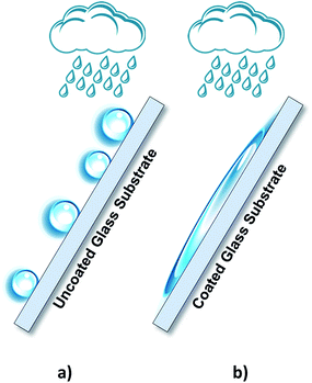 | ||
| Fig. 1 Schematic representation of water droplets behaviour over (a) uncoated glass substrates and (b) TiO2-coated glass substrates exhibiting the photoinduced superhydrophilicity state. | ||
Titanium dioxide-photoinduced superhydrophilicity (PSH) is not yet completely understood and different mechanisms have been proposed in literature.9 Miyauchi and co-workers10 have attributed the PSH to structural changes at the surface. Photogenerated excitions (e−/h+) participate in the surface reduction and oxidation of the TiO2 sites. Ti4+ sites are reduced to Ti3+ and oxygen vacancies are created at the two-coordinated bridging oxygen bonds as follows:10
 | (1) |
| O(O)2− + 2h+ → V(O) + 1/2O2 | (2) |
| Ti4+ + e− → Ti3+ | (3) |
The highly hydrophilic surface of TiO2 can be ascribed to the Ti3+ sites, which are favorable to dissociative water adsorption and thereby create hydrophilic domains, with water contact angles close to zero.11 Wang et al.11 observed a gradual reversion of these domain structures, i.e. the weakly bound hydroxyl groups (–OH) reactively desorbed from the surface after some days under dark conditions.12,13
Titanium dioxide is highly resistant to corrosion; moreover, it is cheap, environmentally friendly, and a widely available semiconductor.14 Different deposition techniques can be used to prepare the transparent thin films of TiO2: doctor blade,15 spray pyrolysis,16 chemical vapour deposition (CVD),17 sol–gel,18 sputtering,19 and spin coating.20 In this study, pristine TiO2 thin films were deposited over soda-lime glass substrates via spin coating to obtain a superhydrophilic, transparent and adherent coating to improve the overall efficiency of the PEC devices for solar hydrogen production.1
2. Experimental
2.1 Preparation of the thin TiO2 films
Soda-lime glass substrates, 10 × 5 cm2, were cleaned to remove contaminants and greasy impurities: first, the glass substrates were washed under ultrasonic conditions in an alconox/water solution, then washed with pure ethanol, and finally treated in a UVO-cleaner for 20 min. A two-step method was used to deposit the TiO2 films over soda-lime glass substrates. In the first step, the cleaned substrates were immersed in a 40 mM aqueous solution of titanium(IV) chloride tetrahydrofuran complex ([TiCl4·2THF], reagent grade 97 wt%, Sigma-Aldrich) for 30 minutes at 70 °C. The prepared films were then annealed at 200 °C for 30 minutes using a blow dryer. In the second step, titanium dioxide paste (Dyesol Industries Pty, 18 NRT) was diluted in ethanol (reagent grade 99.5 vol%, Aga) at 1![[thin space (1/6-em)]](https://www.rsc.org/images/entities/char_2009.gif) :
:![[thin space (1/6-em)]](https://www.rsc.org/images/entities/char_2009.gif) 4 wt% and stirred for 20 minutes at room temperature to achieve good homogenization. The prepared dispersion was then deposited on glass substrates via spin coating (5 mL of solution, spin speed of 2000 rpm for 20 s). Finally, the as-deposited film was heat-treated in air for 45 minutes at 465 °C in a blow dryer.
4 wt% and stirred for 20 minutes at room temperature to achieve good homogenization. The prepared dispersion was then deposited on glass substrates via spin coating (5 mL of solution, spin speed of 2000 rpm for 20 s). Finally, the as-deposited film was heat-treated in air for 45 minutes at 465 °C in a blow dryer.
2.2 Characterization techniques
The TiO2 film thickness was determined via SEM (FEI Quanta 400FEG) analysis, and the transmittance spectra were obtained using a UV-vis spectrometer (UV 3600, Shimadzu) in the wavelength range from 200 to 800 nm. Surface hydrophilicity was examined via water contact angle measurements (OCA 20, DataPhysics) before and after 30 minutes exposure to UV light irradiation. The chemical composition of the TiO2 film was analysed by Fourier transform infrared (FTIR) spectroscopy using Vertex 70 from Bruker equipped with an ATR cell. The films were measured in the 400–4000 cm−1 spectral range with the resolution of 4 cm−1 and spectra of 64 scans were obtained.3. Results and discussion
The replacement of the front window in a PEC device for solar hydrogen production (normally made of quartz) by a TiO2-coated window enhances the light harvesting of the photoelectrode and implies the development of a transparent TiO2 thin film, crack-free and with a good adhesion to the glass substrate. Several deposition techniques were considered: spin coating, doctor blade, spray pyrolysis, and sputtering. The films deposited via doctor blade, spray pyrolysis, and sputtering significantly reduced the transparency of the glass window and were then abandoned.16,21–23 Moreover, the film deposited via doctor blade also showed weak adhesion to the glass substrate. Spin coating technique showed the best results in terms of both transparency and adherence. The spin coating deposition was then optimized in terms of mass ratio of the TiO2 paste and ethanol solvent, spin time, spin velocity, and spin acceleration. A pre-treatment with TiCl4·2THF was also performed since it was reported that a chemical bath of TiCl4·2THF favored the bonding strength with the subsequent TiO2 layer.24 The pre-treated glass windows were then spin-coated with the prepared TiO2 dispersion. After solvent evaporation, they were annealed at 465 °C for 45 min, as described in the experimental section.3.1 Optical and morphological properties of the applied coatings
High film transparency is a critical requirement for the final application of the developed coatings. Fig. 2 compares the transmittance of the uncoated and TiO2-coated glass window samples for the wavelength range between 200 nm and 800 nm. In the spectral range between 350 nm and 800 nm, the transmittance of both samples was ca. 90%. However, an earlier drop was observed in the transmittance of the coated sample for wavelengths smaller that ca. 390 nm due to the presence of the anatase phase. Between 400 nm and 600 nm, the coated sample showed slightly lower transmittance; this was assigned to a larger light scattering on the coated sample due to its surface roughness and higher refractive index, n = 2.52, of the anatase phase, whereas the refractive index of the soda-lime glass was about n ≈ 1.52.25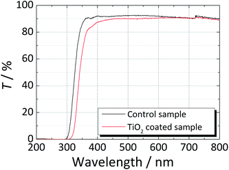 | ||
| Fig. 2 Transmittance spectra of a regular soda-lime glass (control glass) and a soda-lime glass coated with TiO2 in the wavelength range from 200 nm to 800 nm. | ||
Fig. 3 shows the top and cross-section SEM images of the obtained TiO2 films. These films were homogeneous, densely packed, and crack-free with very small grains. This favorable morphology can be ascribed to the TiCl4·2THF pre-treatment, which improved the bonding of the glass substrate to the TiO2 nanoparticles layer. The film thickness was estimated to be ca. 260 nm based on the cross-sectional SEM images.
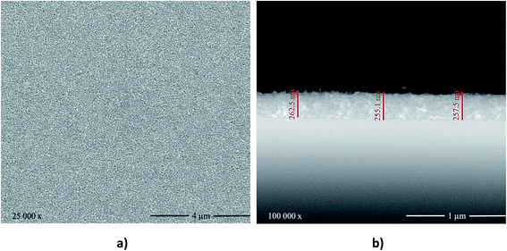 | ||
| Fig. 3 (a) Top-view and (b) cross-section SEM images of the TiO2 films deposited on soda-lime glass via spin coating. | ||
FTIR spectra of the uncoated and coated glass substrates before and after the UV light activation are shown in Fig. 4. In the control glass sample, a strong band at 1000–800 cm−1 associated to the symmetric stretching of pure SiO2 (Si–O–Si bonds) was observed. When TiO2 was deposited over the glass substrate, the intensity of the Si–O–Si bonds was found to decrease and a shift towards lower frequencies was observed. This shift can be associated to the presence of Si–O–Ti bonds, confirming the good adhesion between the glass substrate and the TiO2 film.
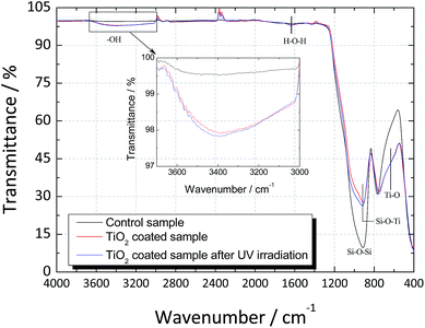 | ||
| Fig. 4 FTIR Spectrum of the regular soda-lime glass and TiO2-coated glass before and after UV light activation. | ||
In the TiO2-coated sample, a broad transmittance peak was observed at 3400 cm−1 that was assigned to the stretching modes of O–H bond due to the surface absorbed water.26 The peak at 1625 cm−1 corresponded to the bending vibration of H–O–H bond was related to the chemisorbed water.27 After UV light activation, a slight increase in both peaks was observed, confirming that TiO2 had higher capacity to adsorb water from moist environments when irradiated with UV light.26
Finally, the band observed at 550 cm−1 in the spectrum of the TiO2-coated sample can be attributed to the vibrations of the Ti–O bonds, and the appearance of a shoulder in this band confirms that pure TiO2 has been deposited.
3.2 Photoinduced superhydrophilicity of the TiO2 coating
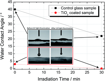
The wettability transition of the TiO2 coating was studied by measuring the water contact angle (WCA) before and after UV illumination (365 nm, 2 W m−2). Fig. 5 shows the plots of the WCA for uncoated (control) and TiO2-coated samples before and after 30 min of UV irradiation. The non-irradiated coated surface presented a water droplet contact angle of ca. 3°, which was considerably lower than that of the uncoated sample (ca. 40°). After UV illumination for 30 minutes, the coated sample exhibited a WCA of ca. 0°, thereby indicating that the photoinduced superhydrophilicity state was achieved.28As explained earlier, hydrophilicity is related to the density of the hydroxyl groups present in the surface of the TiO2 film. They are able to combine with water molecules to form hydrogen bonds, thereby promoting the surface wettability.28 Accordingly, higher surface areas lead to a more hydrophilic film. In fact, the SEM top-view image, as shown in Fig. 3a, indicates a porous coating made of small TiO2 particles, which promotes natural impregnation of atmospheric water; the latter improved the surface wettability, and consequently, lower WCA values were obtained.29
3.3 Experimental setup to simulate H2 and O2 evolution in a PEC cell
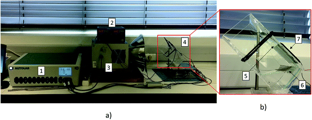
The uncoated and TiO2-coated glass windows were tested in the experimental setup depicted in Fig. 6. The assembled setup comprised a quartz vessel filled with 1 M NaOH aqueous solution, and two platinum meshes (Alfa Aesar, Germany) were used as a counter- and working-electrode connected to a DC power supply to promote the electrolysis of water (ca. 10 mA cm−2 of current density). A Plasma-I AS1300 solar simulator (Plasma International, Germany) equipped with a standard sulphur lamp was used as a light source, and a cSi-PV cell with an active area of 25 cm2 (ETM 750 – 0.5 V, Everstep, China) was placed in the opposite side and connected to a potentiostat workstation (Metrohm Autolab, Netherlands). Each glass window was then immersed in the electrolyte between the light source and the cSi-PV cell, as displayed in Fig. 6. The measurement of the photocurrent produced by the cSi-PV cell was used to evaluate the overall transparency of the glass windows with the evolving bubble curtain. One of the platinum meshes was adequately positioned for producing gas bubbles towards the window surface, as depicted in Fig. 6b. Depending on the polarity applied to the platinum mesh, oxygen (positive) or hydrogen (negative) was formed.The photocurrent produced by the cSi-PV cell was measured in two configurations: vertical and tilted, as shown in Fig. 7. The vertical configuration, 90° (Fig. 7a), was also studied since this is the common configuration used during lab characterizations. On the other hand, the tilted configuration, 45° (Fig. 7b), allowed the simulation of a PEC cell operating under real outdoor conditions for maximizing the amount of light reaching the photoactive material. The cSi-PV cell current density was measured in the following cases: (i) no gas evolution (blank measurement); (ii) when hydrogen bubbles strike the glass window; and (iii) when oxygen gas reaches the glass window. In the blank experiment (with no gas evolution), the photocurrent signals from the cSi-PV cell with and without coating were approximately the same.
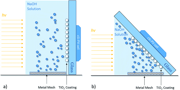 | ||
| Fig. 7 Schematic representation of different configurations for assessing the photocurrent density under (a) vertical position, 90°, and (b) tilted position, 45°. | ||
Fig. 8 shows the photocurrent signal from the cSi-PV cell for the vertical position at 90° (J90°) normalized by the photocurrent signal obtained for the blank determination, (Jblank@90°). No difference was observed when coated or uncoated glass windows were used since the gas bubbles (H2/O2) followed a natural vertical upward movement, not directly hitting on the glass surface (see Fig. 7a). Moreover, when O2 was evolving, the photocurrent signal read by the cSi-PV cell was lower than that when H2 was produced. This can be related to the larger size of the oxygen bubbles. Moreover, in both case-scenarios, the presence of bubbles affected the transmittance within the reactor.
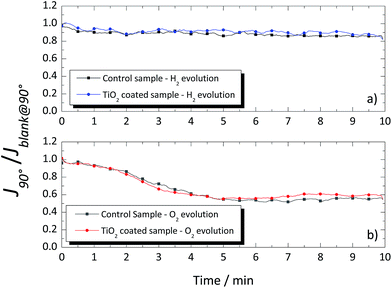 | ||
| Fig. 8 Normalized photocurrent signal of the cSi-PV cell vs. time for the coated and uncoated glass windows when placed vertical for (a) hydrogen and (b) oxygen evolutions. | ||
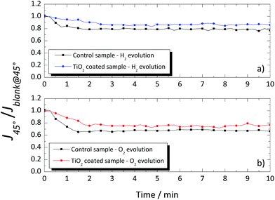
A different response was obtained when the glass windows were positioned at 45°, as shown in Fig. 9. Again, a blank measurement, without gas evolution (Jblank@45°), was performed, and the obtained values were used to normalize the photocurrent density obtained when H2 or O2 was being produced (J45°). In the 45° tilted configuration, the photocurrent signal was higher for the coated glass than that for the uncoated glass window, both for evolution of H2 and O2 as shown in Fig. 9a and b, with ca. 9% and 10%, respectively. The overall improvement of the TiO2-coated glass was assigned to the thin homogenous water film formed on the hydrophilic surface, which prevented the adhesion of the evolved gas bubbles. On the other hand, the evolved gas bubbles tend to slow-down over the untreated glass surface. The results obtained with the TiO2-coated glass windows showed the effectiveness of this layer in reducing the drag against the natural upward movement of the evolved gases nearby the window. Moreover, it is expected that in larger cells, the differences between the coated and uncoated windows would be greater due to the larger amount of the evolving bubbles.
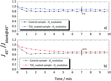 | ||
| Fig. 9 Normalized photocurrent signal of the cSi-PV cell vs. time for the coated and uncoated glass windows when placed at 45° for (a) hydrogen and (b) oxygen evolutions. | ||
In the PEC cells used for solar hydrogen production, the use of the developed coated window can improve their overall efficiency, especially when there is no upward circulation of the electrolyte. It can also decrease the needed electrolyte flow rate when considered, saving the pump energy. Additionally, the use of a superhydrophilic, photoactive layer may also be of interest for photobioreactors where biofilm formation can be delayed or even avoided.30,31
4. Conclusion
An optically transparent, superhydrophilic, and stable TiO2 coating was developed to improve the overall efficiency of tilted PEC cells for solar H2 production. The thin-TiO2 film (ca. 260 nm) was deposited via spin coating on soda-lime glass windows. A homogeneous, crack-free, and strongly bonded coating was obtained. The superhydrophilic state of the coating was assessed from the water contact angle. The optimized TiO2 film presented a water contact angle of ca. 0° when irradiated with UV light.An experimental test bench was assembled to assess the use of TiO2-coated glass windows in PEC cells for water splitting. As expected, the accumulation of evolved gas bubbles at a tilted window surface reduced the light reaching the photoelectrode. When the uncoated glass window was replaced by a TiO2-coated glass window in a 45° tilted configuration, the relative photocurrent signal obtained by the cSi-PV cell increased ca. 9% and 10% for the oxygen and hydrogen evolutions, respectively. Moreover, the performance of the coated glass window was proven to be stable for more than 10 h. The obtained results were relevant for the envisioned use of PEC panels for solar hydrogen production.
Acknowledgements
S. Miranda and A. Vilanova would like to acknowledge the European Union's Seventh Framework Programme (FP7/2007–2013) for Fuel Cells and Hydrogen Joint Technology Initiative under grant agreement no. 621252 – PECDEMO. T. Lopes is grateful to the Portuguese Foundation for Science and Technology (FCT) for her Postdoctoral Grant (Reference: SFRH/BPD/102408/2014). The research leading to these results has received funding from (i) POCI-01-0145-FEDER-006939 (Laboratory for Process Engineering, Environment, Biotechnology and Energy – UID/EQU/00511/2013) funded by the European Regional Development Fund (ERDF), through COMPETE2020 – Programa Operacional Competitividade e Internacionalização (POCI) and by national funds, through FCT – Fundação para a Ciência e a Tecnologia, and (ii) NORTE-01-0145-FEDER-000005 – LEPABE-2-ECO-INNOVATION, supported by North Portugal Regional Operational Programme (NORTE 2020), under the Portugal 2020 Partnership Agreement, through the European Regional Development Fund (ERDF).References
- R. V. D. Krol, Y. Liang and J. Schoonman, Solar hydrogen production with nanostructured metal oxides, J. Mater. Chem., 2008, 18(20), 2311–2320 RSC.
- T. Lopes, L. Andrade and A. Mendes, Photoelectrochemical cells for hydrogen production from solar energy in Solar Energy Sciences and Engineering Applications, ed. N. E. A. Akbarzadeh, CRC Press, 2013 Search PubMed.
- T. Lopes, et al., An innovative photoelectrochemical lab device for solar water splitting, Sol. Energy Mater. Sol. Cells, 2014, 128, 399–410 CrossRef CAS.
- F. Trieb, Concentrating solar power for the mediterranean region, German Aerospace Center (DLR), Germany, 2004 Search PubMed.
- L. J. Minggu, W. R. W. Daud and M. B. Kassim, An overview of photocells and photoreactors for photoelectrochemical water splitting, Int. J. Hydrogen Energy, 2010, 35(11), 5233–5244 CrossRef CAS.
- K. Nakata and A. Fujishima, TiO2 photocatalysis: design and applications, J. Photochem. Photobiol., C, 2012, 13(3), 169–189 CrossRef CAS.
- A. Fujishima and K. Honda, Electrochemical photolysis of water at a Semiconductor Electrode, Nature, 1972, 238(5358), 37–38 CrossRef CAS PubMed.
- R. Wang, K. Hashimoto and A. Fujishima, Light-induced amphiphilic surfaces, Nature, 1997, 388, 431–432 CrossRef CAS.
- A. V. Emeline, et al., Factors affecting UV-induced superhydrophilic conversion of a TiO2 surface, J. Phys. Chem. C, 2013, 117(23), 12086–12092 CAS.
- M. Miyauchi, et al., Photoinduced surface reactions on TiO2 and SrTiO3 films:
![[thin space (1/6-em)]](https://www.rsc.org/images/entities/char_2009.gif) photocatalytic oxidation and photoinduced hydrophilicity, Chem. Mater., 2000, 12(1), 3–5 CrossRef CAS.
photocatalytic oxidation and photoinduced hydrophilicity, Chem. Mater., 2000, 12(1), 3–5 CrossRef CAS. - R. Wang, et al., Photogeneration of highly amphiphilic TiO2 surfaces, Adv. Mater., 1998, 10(2), 135–138 CrossRef CAS.
- A. Fujishima, T. N. Rao and D. A. Tryk, Titanium dioxide photocatalysis, J. Photochem. Photobiol., C, 2000, 1, 1–21 CrossRef CAS.
- O. Carp, C. L. Huisman and A. Reller, Photoinduced reactivity of titanium dioxide, Prog. Solid State Chem., 2004, 32(1), 33–177 CrossRef CAS.
- R. Dholam, et al., Hydrogen production by photocatalytic water-splitting using Cr-or Fe-doped TiO2 composite thin films photocatalyst, Int. J. Hydrogen Energy, 2009, 34(13), 5337–5346 CrossRef CAS.
- J. Akilavasan, M. Al-Jassim and J. Bandara, Designing nanostructured one-dimensional TiO2 nanotube and TiO2 nanoparticle multilayer composite film as photoanode in dye-sensitized solar cells to increase the charge collection efficiency, J. Nanophotonics, 2015, 9(1), 093091 CrossRef.
- A. Nakaruk, D. Ragazzon and C. C. Sorrell, Anatase thin films by ultrasonic spray pyrolysis, J. Anal. Appl. Pyrolysis, 2010, 88(1), 98–101 CrossRef CAS.
- H.-Y. Lee and H.-G. Kim, The role of gas-phase nucleation in the preparation of TiO2 films by chemical vapor deposition, Thin Solid Films, 1993, 229(2), 187–191 CrossRef CAS.
- M. A. M. L. de Jesus, et al., Superhydrophilic self-cleaning surfaces based on TiO2 and TiO2/SiO2 composite films for photovoltaic module cover glass, Appl. Adhes. Sci., 2015, 3(1), 5 CrossRef.
- K.-S. Lee and S. H. Lee, Influence of SiO2 interlayer on the hydrophilicity of TiO2/SiO2/glass produced by RF-magnetron sputtering, Mater. Lett., 2007, 61(16), 3516–3518 CrossRef CAS.
- A. Mills, et al., Thick titanium dioxide films for semiconductor photocatalysis, J. Photochem. Photobiol., A, 2003, 160, 185–194 CrossRef CAS.
- B. A. Nejand, S. Sanjabi and V. Ahmadi, The effect of sputtering gas pressure on structure and photocatalytic properties of nanostructured titanium oxide self-cleaning thin film, Vacuum, 2010, 85(3), 400–405 CrossRef CAS.
- Y. Wang, et al., Development of high dispersed TiO2 paste for transparent screen-printable self-cleaning coatings on glass, J. Nanopart. Res., 2013, 15(1), 1384 CrossRef.
- A. I. Martinez, D. R. Acosta and A. A. Lopez, Effect of deposition methods on the properties of photocatalytic TiO2 thin films prepared by spray pyrolysis and magnetron sputtering, J. Phys.: Condens. Matter, 2004, 16(22), S2335 CrossRef CAS.
- S. Ito, et al., Fabrication of thin film dye sensitized solar cells with solar to electric power conversion efficiency over 10%, Thin Solid Films, 2008, 516(14), 4613–4619 CrossRef CAS.
- D.-J. Won, et al., Effects of thermally induced anatase-to-rutile phase transition in MOCVD-grown TiO2 films on structural and optical properties, Appl. Phys. A: Mater. Sci. Process., 2001, 73(5), 595–600 CrossRef CAS.
- K. Hashimoto, H. Irie and A. Fujishima, TiO2 photocatalysis: a historical overview and future prospects, Jpn. J. Appl. Phys., 2005, 44(12R), 8269 CrossRef CAS.
- J. M. H. Enríquez, et al., Synthesis of Solid Acid Catalysts Based on TiO2–SO42−and Pt/TiO2–SO42− Applied in n-Hexane Isomerization, Open J. Met., 2013, 3, 34–44 CrossRef.
- C. Euvananont, et al., TiO2 optical coating layers for self-cleaning applications, Ceram. Int., 2008, 34(4), 1067–1071 CrossRef CAS.
- M. Houmard, et al., Morphology and natural wettability properties of sol–gel derived TiO2–SiO2 composite thin films, Appl. Surf. Sci., 2007, 254(5), 1405–1414 CrossRef CAS.
- J. Wang, J. Liu and T. Liu, The difference in effective light penetration may explain the superiority in photosynthetic efficiency of attached cultivation over the conventional open pond for microalgae, Biotechnol. Biofuels, 2015, 8, 49 CrossRef PubMed.
- O. Zeriouh, et al., Biofouling in photobioreactors for marine microalgae, Crit. Rev. Biotechnol., 2017, 1–18 CrossRef PubMed.
Footnote |
| † Part of this work was presented at 2016 MRS Fall Meeting & Exhibit, Boston, Massachusetts. |
| This journal is © The Royal Society of Chemistry 2017 |

