 Open Access Article
Creative Commons Attribution 3.0 Unported Licence
Strong and resilient alumina nanotube and CNT/alumina hybrid foams with tuneable elastic properties†
Kelly L. Stano,
Shaghayegh Faraji,
Ozkan Yildiz,
Halil Akyildiz,
Philip D. Bradford and
Jesse S. Jur *
*
North Carolina State University, Department of Textile Engineering, Chemistry & Science, Raleigh NC 27965, USA. E-mail: jsjur@ncsu.edu
First published on 26th May 2017
Abstract
Excellent chemical and heat resistance combined with the attractive properties of aerogels, including large surface area and low density makes alumina aerogels an attractive material for high temperature catalysis, thermal insulation, and vibration damping. Brittle behaviour, a high propensity to sinter, and poor moisture stability, however, have drastically inhibited the practical use of alumina aerogels produced using traditional methods. Herein, we report the scalable fabrication of low density, anisotropic carbon nanotube (CNT)/alumina hybrid foams synthesized via atomic layer deposition (ALD) on aligned carbon nanotube foams (CNTFs). Calcination of the hybrid foams in air resulted in removal of the CNTFs, leaving behind a free-standing three-dimensional network of interconnected alumina nanotubes. Both CNT/alumina hybrid foams and pure alumina nanotube foams exhibit unprecedented elastic recovery following 50% compression, and possess values for strength and Young's moduli which exceed those of aerogels with similar densities. The scaling behaviour of Young's modulus to foam density for pure alumina foams exhibits a power-law dependence of n ≈ 1.9, attributed to superb ligament connectivity. These unique structures remain stable to the large capillary forces induced upon liquid infiltration and removal, and can absorb up to 100 times their own weight in water. Furthermore, alumina nanotube foams demonstrate enhanced thermal insulation capabilities at temperature of 1000 °C with no evidence of shrinkage.
Introduction
Aerogels and related cellular materials are characteristically unique from their solid counterparts due to their high porosity, low density, and large specific surface area. These properties make them desirable for a multitude of applications.1 As a structural ceramic, alumina and alumina-based materials are highly regarded for their high strength in addition to good chemical and thermal stability. Many of these properties have been shown to translate to low density alumina aerogels, with the exception of mechanical resilience. In particular, studies on the preparation of mechanically robust monolithic alumina aerogels with high heat resistance are limited. Although alumina aerogels are known to have superior heat resistance compared to silica, which sinters above 600 °C,2 their fragility has limited their practical use. High temperature stability and chemical resistance combined with durability would make alumina aerogels attractive for high temperature catalysts and/or catalyst supports, sensors, thermal insulators, structural composites, and many other applications.3–5There are significant challenges associated with producing low density, monolithic alumina aerogels that are mechanically robust and structurally uniform. Even at low strains, most non-silica aerogels, particularly alumina, are notoriously fragile.6 The mechanical properties of porous materials are known to degrade significantly with decreasing density.7 They exhibit a scaling behaviour between modulus and density as well as strength and density described by the relationship E/Es ∼ (ρ/ρs)n and σy/σys ∼ (ρ/ρs)n, where E is Young's modulus, ρ is density, σy is yield strength, and s denotes the respective property value of the particular solid material. The power of n is microstructure-specific and describes the deformation mechanisms of the structural components within the cellular architecture.8 Superior mechanical properties can be attained using highly ordered lattices with stretching-dominated geometries which scale more linearly, where 1 ≤ n ≤ 2.7,9,10 Cellular geometries featuring either stochastic or periodic porosity that instead deform by bending-dominated mechanisms exhibit a steep scaling behaviour, where n ≥ 2.11 Traditional aerogels are known to exhibit even higher scaling behaviours (n ≥ 3) due to their fractal geometries and disconnected structures.12
Alumina aerogels have historically been produced using sol–gel methods; though large-scale, un-cracked, and uniform monolithic aerogels are difficult to achieve.3,5,6 Furthermore, these techniques afford little control over cellular architecture such as pore size and distribution, particularly for very low densities (≤20 mg cm−3). Alternatively, there has been growing interest in the development of novel methods to produce mesoporous metal oxide materials with ordered architectures.13 Many of these techniques rely on the use of a template onto which material is deposited, which may be followed by removal of the template.
Atomic layer deposition (ALD) has emerged as a preferred technique for template coating due to its ability to conformally coat high aspect ratio and high surface area nanostructured substrates with continuous thin films at high levels of precision.14 ALD of alumina on sacrificial templates such as nanocellulose aerogels,15 mesoporous block copolymers,16 and nanoporous gold,17 has resulted in high surface area materials structures with unique interconnected nanotubular morphologies, but the resulting aerogels are fragile and have film-like thicknesses. Highly engineered micro- and nanolattice geometries have been prepared using ALD to deposit alumina on digitally designed and lithographically fabricated sacrificial polymer templates.9,10,18,19 Lithography-based template preparation, however, limits the minimum attainable feature size resulting in low volumetric surface area. Though proficient in creating optimized architectures, these templates are also limited in their ability to scale-up manufacturing for large-scale foams due to complexity and cost.
Carbon nanotubes (CNTs) are an intriguing alternative to other template materials. Optimization of chemical vapour deposition (CVD) synthesis methods have made it possible to economically produce bulk-quantities of CNTs.20 Moreover, recent advances in processing technologies have led to the creation of various one, two, and three-dimensional large-scale and ordered assemblies including vertically aligned arrays, ribbons and sheets, yarns, and aerogels, sponges, or foams.21 CNT foams (CNTFs) have been manufactured via single-step CVD,22 and multi-step aqueous gel and critical point drying synthesis techniques.23 The resulting foams are porous and high surface area, and are composed of randomly oriented 3D networks of CNTs. Though elastic and compressible, these foams are often low stiffness due to the weak van der Waals interactions at CNT–CNT junctions as well as poor alignment of CNTs in the direction of loading.
Previously, we have developed a technique to produce ultralow density, large-scale, and aligned CNTFs that demonstrate anisotropic mechanical, electrical, and thermal properties.24 This was achieved via chemical vapour infiltration (CVI) of pyrolytic carbon (PyC) into thick stacks of aligned CNT sheets drawn from spinnable arrays and continuously collected on a rotating mandrel. Varying the duration of CVI treatment allowed for tuning of mechanical properties due to radial growth and thickening of CNT struts, and also encapsulation of CNT–CNT junctions with PyC. This effectively created physical crosslinks in the foam structure which provided a collective restoring force to reverse the compressive strain. The unique properties of these aligned CNTFs make them an interesting template for fabrication of metal oxide foams.
Herein, we report on the fabrication of large-scale pure alumina and CNT/alumina hybrid foams via ALD on aligned CNTFs. The mechanical properties of these foams were investigated as a function of density (controlled by alumina coating thickness), and nanotube alignment. All foams were found to exhibit unprecedented elastic recovery after being compressed to 50% strain, with total apparent recovery for thin-walled specimens. The Young's moduli for these foams exceeded that of any other aerogel with similar density. The scaling behaviour of Young's modulus to foam density for CNT/alumina hybrid foams was found to follow that of CNT aerogels, where n ≈ 2.6. Pure alumina foams, however, exhibited a power-law dependence of n ≈ 1.9 attributed to enhanced ligament connectivity and efficient load-transfer.
Experimental
Materials and methods
Characterization
SEM was conducted on a FEI XHR-Verios 460L field emission SEM. Samples were not sputter-coated prior to imaging. For TEM, a JEOL 2010F field emission STEM was used. Micrographs were recorded using a Gatan Orius digital camera. Bulk density (ρ) was calculated by ρ = M/V, where M and V are bulk mass and bulk volume of the specimens. Bulk volume was calculated by V = l × w × h, where l, w, and h are length, width, and height of the specimens, respectively. Sample dimensions were taken using digital calipers and averaged over three measurements. Masses were measured using a Denver Instrument M-220D balance with 0.01 mg accuracy. Thermogravimetric analysis (TGA) experiments were conducted on a Perkin Elmer Pyris 1 TGA using 5–10 mg of each sample heated at a rate of 10°C min−1 in air to 800 °C, and then isothermally soaked for 30 minutes. Cyclic uniaxial compression testing was conducted on an Instron 5544 mechanical tester. The load rate was 5 mm min−1, and a 100N load cell was used for all samples. Samples were loaded to 50% strain then unloaded, and this was repeated for a total of 5 cycles. Foams were tested in both transverse (nanotube axes perpendicular to load) and longitudinal (nanotube axes parallel to load) directions.Results and discussion
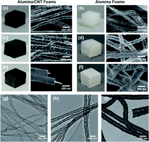
Pristine stacks of aligned CNTs were easily and permanent deformed due to limited ligament connectivity and insufficient energy to overcome the van der Waals adhesion forces generated from compression and increased CNT–CNT contact area. In contrast, PyC deposition on CNT stacks resulted in radial growth of CNTs and encapsulation of CNT bundles and CNT–CNT junctions, essentially creating a three-dimensional interconnected network of aligned CNTs. Foam-like recovery observed in these samples was attributed to the newly created physical crosslinks which provided increased capacity for energy storage upon compression which provided a recovery force larger than accumulated van der Waals adhesion forces.24 Additionally, CNTFs featured enhanced processability and could be easily cut to the desired dimensions using a razor blade or laser cutter. The ability to precisely machine the templates in the manner is a highly unique feature of this process, as complex sub-millimetre architectures with controlled depth profiling can be generated.Atmospheric pressure oxygen plasma treatment was employed to functionalize the inert CNTF surface, and encourage dense nucleation of ALD precursor molecules. As a result, continuous alumina films measuring only 2.5 nm thick were found on the CNTF surfaces after only 20 ALD cycles as shown in Fig. 1(a), (b) and (g). Due to good conformality of the coating, CNT–CNT junctions were also coated and preserved in the structure. The use of ALD, combined with highly porous ultralow density CNTF templates allowed for large-scale samples to be fabricated without sacrificing uniformity. Due to its sequential and self-limiting reactions, ALD is highly regarded for producing precisely thick coatings on high aspect ratio and high surface area substrates. Nanoporous templates with very high aspect ratios, however, have an upper limit for practically achievable dimensions (on the order of 10–100 s of micrometres) due to limited precursor diffusion within their highly tortuous structures.16,17,26 Although the largest samples we have currently produced measure ∼13 cm (l) × 8 cm (w) × 1.5 cm (h), advances in commercial CVI and ALD equipment may readily scale our method for the production of truly bulk quantities.
The thickness of alumina was controlled by varying the number of cycles as shown in the SEM micrographs provided in Fig. 1. Alumina film thicknesses measured 12 and 63 nm for 100 and 500 cycles, respectively, corresponding to a growth rate of 1.2 Å per cycle which correlated well with the film thickness measured from a control Si wafer using ellipsometry. CNTFs were oxidatively removed via calcination in air, leaving behind an interconnected network of hollow alumina nanotubes. The tubular morphology as well as coated junctions were maintained for all coating thicknesses studied, which is visible in the TEM micrographs provided in Fig. 1(g)–(i). As-deposited alumina was determined to be amorphous while removal of CNTFs through calcination resulted in crystallization of the alumina to form η-Al2O3.27
The plot in Fig. 2 illustrates that the density of alumina/CNT foams and pure alumina foams increased linearly with the number of ALD cycles and spanned ranges of ∼6–45 and ∼1–40 mg cm−3, respectively. The lowest density achieved, 1.2 mg cm−3, is the lowest for an alumina aerogel reported to date, and is among the lowest overall for any inorganic material.11,28 Even the highest density demonstrated in this work (39 mg cm−3), is lower than that of alumina aerogels fabricated using sol–gel methods.3,5,6 Thermogravimetric analysis, provided in Fig. 2, revealed that alumina coated CNTFs exhibited good thermal stability with minimal weight loss at low temperature. The onset of decomposition from CNT oxidation increased with coating thickness, confirming conformal coverage. Additionally, the mass% remaining at the end of testing for each sample correlated well with the actual mass of ALD added as measured by a microbalance. Furthermore, Brunauer–Emmett–Teller (BET) analysis of the surface area of the 20 ALD cycle alumina/CNT foam samples (the thinnest coatings) was previously determined.27 Prior to ALD deposition, the CNT foam samples had a surface area of 59 m2 g−1, which decreased to 34 m2 g−1 after 20 ALD cycles of alumina. After burning out the CNTs, the surface area increased it to 265 m2 g−1.
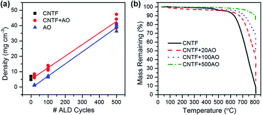 | ||
| Fig. 2 (a) Linear dependence of CNTF/alumina and alumina foam density on # of ALD cycles. (b) Mass loss as a function of temperature for CNTFs coated for 0, 20, 100, and 500 cycles of ALD. | ||
Compression testing
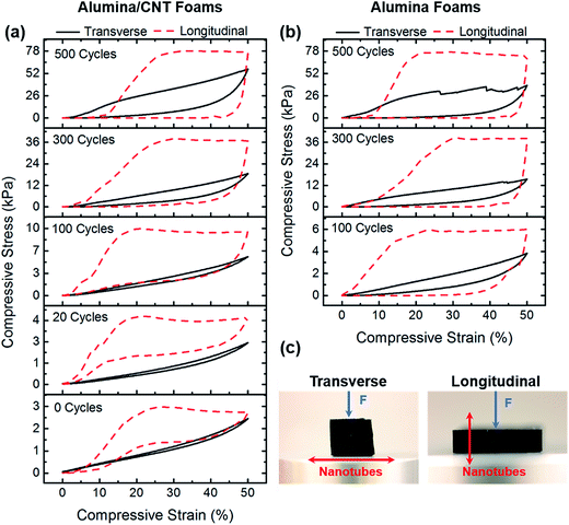
Pure alumina and CNT/alumina composite foams were compressed in transverse and longitudinal directions to characterize their mechanical properties. Representative stress–strain curves for each sample are provided in Fig. 3. The mechanical response transitioned from elastomeric for thin-walled and hybrid foams to elastic–brittle behaviour for thick-walled and pure alumina foams. Low density foams demonstrated super-compressibility and tuneable elastic behaviour. During transverse compression, the nanotube axes were oriented perpendicular to the direction of loading. All samples tested in this orientation, including composite foams and pure alumina nanotube foams, exhibited some degree of elastic recovery following compression, though recovery was maximized for thin-walled CNT/alumina nanotube foams.This is an interesting result, because elastic recovery behaviour in a pure ceramic foam or aerogel is unprecedented. Typically, aerogels must be modified through the addition of flexible organic polymers to the surface to provide mechanical reinforcement.29 For a material which may find application in high temperature environments, this is obviously not the best solution. CNT/alumina foams coated for 20, 100, and 300 cycles as well as pure alumina 100 cycle foams deformed elastically up to 50% strain. The stress–strain curves from 300AO and 500AO displayed evidence of “strain bursts” which correlate to brittle failure events leading to permanent deformation. Larger strain bursts were measured for thicker-walled samples likely due to their increased capacity for storage of elastic strain energy compared to thinner-walled samples.
In longitudinal compression the nanotube axes were oriented parallel to the direction of loading. All samples initially exhibited linearly elastic deformation until yield. Thin-walled CNT/alumina nanotube foams coated for 20 and 100 cycles underwent ductile-like deformation characterized by the plateau region of the stress–strain curve. These samples exhibited total elastic recovery after 50% compressive strain, indicating that the additional deformation after yield was accommodated by elastic modes such as tube bending and wrinkling.9 Even CNT/alumina foams coated for 300 cycles recovered to 85% of their original height. In contrast, thick-walled CNT/alumina nanotube foams (500 cycles) and all pure alumina nanotube foams behaved in a more brittle manner with only moderate recovery after longitudinal compression. Following yield, these foams plastically deformed through non-recoverable node breakage and tube fracture. It is obvious here that the alignment of the CNTs with respect to compression influences the degree of elastic recovery. With a parallel orientation with respect to compression, the neighbouring support microstructure of the CNTs results in efficient load bearing at node sites without CNT fracture. On-end, in which the compression is occurring down the length of the nanotube, a CNT would likely fracture in between nodes and results in a much lower elastic recovery.
The fatigue behaviour of the foams was evaluated from cyclic compression tests, and representative stress–strain curves for 100 cycle alumina and CNT/alumina foams are presented in Fig. 4 (cyclic compression tests for other samples may be found in ESI, Fig. S1†). Curves from subsequent compression cycles, particularly for denser foams, exhibited a pseudo hardening behaviour where the slope rapidly increased with small strain. This can be attributed to the densification of the structure upon deformation. Although energy absorption degraded quite significantly for most samples following the initial cycle, moduli and maximum stress decreased only slightly. For the remainder of testing, however, all mechanical properties were shown to stabilize.
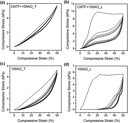 | ||
| Fig. 4 Cyclic compression behaviour for CNTF + 100AO in (a) transverse (T), and (b) longitudinal (L) directions as well as 100AO in (c) transverse, and (d) longitudinal directions. | ||
For quantification of mechanical properties, E was calculated from the initial slope of the unloading curve and strength was determined to be the maximum value of stress on the stress–strain plot. For all samples, modulus increased with the number of ALD cycles. The moduli of pure alumina and CNT/alumina composite foams were the same for a given coating thickness. Specific modulus, however, was higher for all alumina foams due to their lower density from CNT removal. This effect was much less pronounced upon increasing the number of ALD cycles since the CNTs make up a smaller fraction of the total density for thicker alumina coatings.
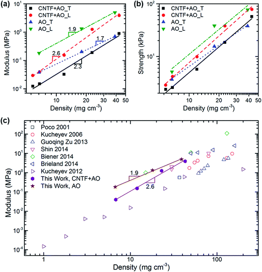
The log–log plots provided in Fig. 5 examine the relationships between compressive modulus, compressive strength, and density. We discovered that alumina nanotube foams exhibited power law scaling behaviours of ET ∼ ρ1.7 and EL ∼ ρ1.9. For cellular geometries with bending-dominated deformation mechanisms a scaling factor of 2 indicates perfect connectivity of the ligaments, and thus efficient load transfer.8 Aerogels typically exhibit scaling factors greater than 3 attributed to their “pearls on a string” microstructure which provides poor ligament connectivity.12 The scaling behaviour of CNT/alumina composite foams was steeper, with ET ∼ ρ2.2 and EL ∼ ρ2.5. Similar scaling factors have been reported for both pure CNT,30,31 and composite CNT aerogels,32 as well as alumina coated CNT arrays.33 As the scaling exponent is related to ligament connectivity, it is possible that pure alumina foams possess enhanced connectivity as a result of film sintering and crystallization which occurs during calcination. SEM images of 100 cycle coated samples before and after CNT removal show that as-deposited alumina is rough and nodular, whereas calcinated films are smooth due to particle sintering.
Fig. 5(c) provides the modulus–density relationships from data published on other aerogels and foams with similar densities. All of our foams match or exceed the other moduli, particularly in the ultralow density regime where our 100 cycle alumina foam had a modulus one order of magnitude higher than that from a silica aerogel of similar density.28 Strength–density relationships were equally impressive. 500 cycle pure alumina and CNT/alumina hybrid foams with densities less than 40 mg cm−3 had strengths near 80 kPa, whereas a commercially available isotropic aluminium foam with twice the density only had strength of 20 kPa.34
Wetting behaviour and liquid absorption capacity
A benefit to the fabrication of mechanically robust CNT/alumina and alumina foams is the added stability to moisture and heat. Metal oxide aerogels typically possess hydroxylated surfaces which result in their being extremely hydrophilic. For many materials this would not be an issue except that, in the case of an aerogel, the strong capillary forces generated upon wetting are often enough to cause catastrophic rupture.35 One route to overcome this deficiency is to make the aerogels hydrophobic, which is commonly accomplished by modification of the sol–gel chemistry, or by coating the aerogel with a polymer.Instead, we demonstrate here that both hybrid and pure alumina foams can be wet without harming their structure. Photographs in Fig. 6 illustrate representative wetting behaviours of the foams. Due to their anisotropy, a water droplet placed on the surface spreads preferentially in the direction of the nanotube axes. This response was observed in all samples, but most visibly apparent in Fig. 6(a) and (b). Despite the fact that the lowest density sample (20AO, Fig. 6(c)) was densified by the droplet, it was found that a gel network formed where the previously existing interconnects were maintained. Upon drying, an alumina nanotube paper was formed. Higher density alumina foams made from 100 and 500 cycle samples remained structurally stable upon wetting. The 100AO foam initially flattened where wet, but as more droplets were added, the foam gradually expanded until it regained its full volume. Photographs in Fig. 6(d) and (e) depict fully saturated CNTF + 100AO and 100AO foams. Finally, after drying in an oven the foams retained their structural integrity with minimal shrinkage.
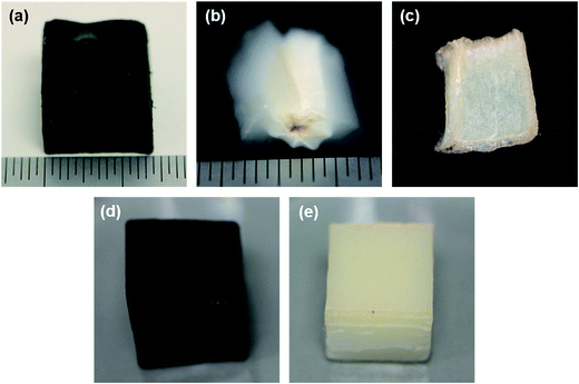 | ||
| Fig. 6 Anisotropic wetting behaviour is shown for (a) CNTF + 20AO and (b) 20AO foams. (c) Densified 20AO foam remains intact and forms a film. Fully saturated (d) CNTF + 100AO and (e) 100AO foams. | ||
The liquid absorption capacity of 100 and 500 cycle CNT/alumina hybrid and pure alumina foams was measured by weighing them dry, and then gradually adding water until they became saturated. The 100AO foams had the largest absorption capacity, holding up to 100 times their own weight in water. This was followed by CNTF + 100AO which held up to 77 times its weight. Likely due to decreased free volume, both 500 cycle samples only absorbed up to 27 times their weight in water. This ability for these foams to retain stability upon wetting has implications for liquid filtration as well as aqueous-based processing routes like solution infiltration or electrochemical deposition.
Thermal stability
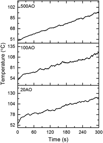
Following the removal of CNTFs via calcination in air at 800 °C, sample dimensions were measured to check for shrinkage. While the width and height did not change, there was some shrinkage along the direction of the nanotube axis. Thought not perceptible by eye, the foam lengths decreased by 2, 6, and 3% for 20AO, 100AO, and 500AO foams, respectively. The thermal insulating ability of alumina foams was evaluated using a flame test. Foam blocks were placed over a flame source and then continuously fired for 5 minutes with a 1000 °C flame. Temperature rise on the top surface of the foams was measured with a thermocouple, and was plotted as function of time, as shown in Fig. 7. The 500AO foam demonstrated the best performance with a total temperature rise of 45 °C. 20AO and 100AO foams rose 63 and 69 °C, respectively. Furthermore, the alumina foams exhibited no signs of damage caused by shrinkage or sintering from continuous high temperature exposure. Further analysis of additional thermal properties of these materials is underway.Conclusions
Carbon nanotube/alumina hybrid foams and pure alumina nanotube foams with ultralow densities were produced via ALD on CNTF templates. The foams exhibited unique anisotropic mechanical properties due to a high level of alignment among the nanotubes. Foams demonstrated unprecedented elastic recovery following compression and exceed some of the highest strength and modulus values for any type of foam with similar density. Pure alumina foams were shown to have a density–modulus scaling dependence of 2, indicating superior ligament connectivity and efficient load transfer. Finally, foams exhibited impressive thermal stability and insulating properties as well as high durability for liquid filtration and drying.Acknowledgements
The authors acknowledge the use of the Analytical Instrumentation Facility (AIF) at North Carolina State University, which is supported by the State of North Carolina and the National Science Foundation. This material is based upon work supported by the National Science Foundation Graduate Research Fellowship Program under grant no. DGE-0946818 and through the Nanosystems Engineering Research Center for Advanced Self-Powered Systems for Integrated Sensors and Technologies under Grant EEC 1160483. The authors would like to thank Dr Marian McCord (NCSU) for use of the plasma equipment, Dr Russell Gorga (NCSU) for use of the Instron.References
- J. L. Gurav, I.-K. Jung, H.-H. Park, E. S. Kang and D. Y. Nadargi, Silica Aerogel: Synthesis and Applications, J. Nanomater., 2010, 2010, 1–11 CrossRef.
- A. Emmerling, J. Gross, R. Gerlach, R. Goswin, G. Reichenauer, J. Fricke and H.-G. Haubold, Isothermal Sintering of SiO2-Aerogels, J. Non-Cryst. Solids, 1990, 125, 230–243 CrossRef CAS.
- J. Poco, J. H. Satcher and L. Hrubesh, Synthesis of High Porosity, Monolithic Alumina Aerogels, J. Non-Cryst. Solids, 2001, 285, 57–63 CrossRef CAS.
- G. Zu, J. Shen, X. Wei, X. Ni, Z. Zhang, J. Wang and G. Liu, Preparation and Characterization of Monolithic Alumina Aerogels, J. Non-Cryst. Solids, 2011, 357, 2903–2906 CrossRef CAS.
- G. Zu, J. Shen, L. Zou, W. Wang, Y. Lian, Z. Zhang and A. Du, Nanoengineering Super Heat-Resistant, Strong Alumina Aerogels, Chem. Mater., 2013, 25, 4757–4764 CrossRef CAS.
- S. O. Kucheyev, T. F. Baumann, C. A. Cox, Y. M. Wang, J. H. Satcher, A. V. Hamza and J. E. Bradby, Nanoengineering Mechanically Robust Aerogels via Control of Foam Morphology, Appl. Phys. Lett., 2006, 89, 041911 CrossRef.
- H. Fan, C. Hartshorn, T. Buchheit, D. Tallant, R. Assink, R. Simpson, D. J. Kissel, D. J. Lacks, S. Torquato and C. J. Brinker, Modulus-density Scaling Behaviour and Framework Architecture of Nanoporous Self-assembled Silicas, Nat. Mater., 2007, 6, 418–423 CrossRef CAS PubMed.
- L. J. Gibson and M. F. Ashby, Cellular Solids: Structure and Properties, Cambridge University Press, Cambridge, 2nd edn., 1999 Search PubMed.
- L. R. Meza, S. Das and J. R. Greer, Strong, Lightweight, and Recoverable Three-Dimensional Ceramic Nanolattices, Science, 2014, 345, 1322–1326 CrossRef CAS PubMed.
- X. Zheng, H. Lee, T. H. Weisgraber, M. Shusteff, J. DeOtte, E. B. Duoss, J. D. Kuntz, M. M. Biener, Q. Ge, J. A. Jackson, S. O. Kucheyev, N. X. Fang and C. M. Spadaccini, Ultralight, Ultrastiff Mechanical Metamaterials, Science, 2014, 344, 1373–1377 CrossRef CAS PubMed.
- T. A. Schaedler, A. J. Jacobsen, A. Torrents, A. E. Sorensen, J. Lian, J. R. Greer, L. Valdevit and W. B. Carter, Ultralight Metallic Microlattices, Science, 2011, 334, 962–965 CrossRef CAS PubMed.
- T. Woignier and J. Phalippou, Scaling Law Variation of the Mechanical Properties of Silica Aerogels Le, J. Phys., Colloq., 1989, 24, C4 CrossRef.
- Y. Ren, Z. Ma and P. G. Bruce, Ordered Mesoporous Metal Oxides: Synthesis and Applications, Chem. Soc. Rev., 2012, 41, 4909 RSC.
- Atomic Layer Deposition of Nanostructured Materials, ed. N. Pinna and M. Knez, Wiley-VCH Verlag GmbH & Co., Weinheim, 2012 Search PubMed.
- J. T. Korhonen, P. Hiekkataipale, J. Malm, M. Karppinen, O. Ikkala and R. H. A. Ras, Inorganic Hollow Nanotube Aerogels by Atomic Layer Deposition onto Native Nanocellulose Templates, ACS Nano, 2011, 5, 1967–1974 CrossRef CAS PubMed.
- F. Li, X. Yao, Z. Wang, W. Xing, W. Jin and J. Huang, Wang, Y. Highly Porous Metal Oxide Networks of Interconnected Nanotubes by Atomic Layer Deposition, Nano Lett., 2012, 12, 5033–5038 CrossRef CAS PubMed.
- M. M. Biener, J. Ye, T. F. Baumann, Y. M. Wang, S. J. Shin, J. Biener and A. V. Hamza, Ultra-Strong and Low-Density Nanotubular Bulk Materials with Tunable Feature Sizes, Adv. Mater., 2014, 26, 4808–4813 CrossRef CAS PubMed.
- D. Jang, L. R. Meza, F. Greer and J. R. Greer, Fabrication and Deformation of Three-Dimensional Hollow Ceramic Nanostructures, Nat. Mater., 2013, 12, 893–898 CrossRef CAS PubMed.
- J. Bauer, S. Hengsbach, I. Tesari, R. Schwaiger and O. Kraft, High-Strength Cellular Ceramic Composites with 3D Microarchitecture, Proc. Natl. Acad. Sci. U. S. A., 2014, 111, 2453–2458 CrossRef CAS PubMed.
- M. F. L. De Volder, S. H. Tawfick, R. H. Baughman and J. Hart, Carbon Nanotubes: Present and Future Commercial Applications, Science, 2013, 339, 535–539 CrossRef CAS PubMed.
- J. Di, X. Wang, Y. Xing, Y. Zhang, X. Zhang, W. Lu, Q. Li and Y. T. Zhu, Dry-Processable Carbon Nanotubes for Functional Devices and Composites, Small, 2014, 10, 4606–4625 CrossRef CAS PubMed.
- X. Gui, J. Wei, K. Wang, A. Cao, H. Zhu, Y. Jia, Q. Shu and D. Wu, Carbon Nanotube Sponges, Adv. Mater., 2010, 22, 617–621 CrossRef CAS PubMed.
- M. B. Bryning, D. E. Milkie, M. F. Islam, L. A. Hough, J. M. Kikkawa and A. G. Yodh, Carbon Nanotube Aerogels, Adv. Mater., 2007, 19, 661–664 CrossRef CAS.
- S. Faraji, K. L. Stano, O. Yildiz, A. Li, Y. T. Zhu and P. D. Bradford, Ultralight Anisotropic Foams from Layered Aligned Carbon Nanotube Sheets, Nanoscale, 2015, 7, 17038–17047 RSC.
- K. L. Stano, M. Carroll, R. Padbury, M. McCord, J. S. Jur and P. D. Bradford, Conformal Atomic Layer Deposition of Alumina on Millimeter Tall, Vertically-Aligned Carbon Nanotube Arrays, ACS Appl. Mater. Interfaces, 2014, 6, 19135–19143 CAS.
- J. W. Elam, G. Xiong, C. Y. Han, H. H. Wang, J. P. Birrell, U. Welp, J. N. Hryn, M. J. Pellin, T. F. Baumann, J. F. Poco and J. H. Satcher, Atomic Layer Deposition for the Conformal Coating of Nanoporous Materials, J. Nanomater., 2006, 2006, 1–5 CrossRef.
- K. L. Stano, S. Faraji, R. Hodges, O. Yildiz, B. Wells, H. Akyildiz, J. Zhao, J. S. Jur and P. D. Bradford, Ultralight Interconnected Metal Oxide Nanotube Networks, Small, 2016, 12, 2432–2438 CrossRef CAS PubMed.
- S. O. Kucheyev, M. Stadermann, S. J. Shin, J. H. Satcher, S. A. Gammon, S. A. Letts, T. Van Buuren and A. V. Hamza, Super-Compressibility of Ultralow-Density Nanoporous Silica, Adv. Mater., 2012, 24, 776–780 CrossRef CAS PubMed.
- H. Maleki, L. Durães and A. Portugal, An Overview on Silica Aerogels Synthesis and Different Mechanical Reinforcing Strategies, J. Non-Cryst. Solids, 2014, 385, 55–74 CrossRef CAS.
- S. J. Shin, S. O. Kucheyev, M. A. Worsley and A. V. Hamza, Mechanical Deformation of Carbon-Nanotube-Based Aerogels, Carbon, 2012, 50, 5340–5342 CrossRef CAS.
- K. H. Kim, Y. Oh and M. F. Islam, Mechanical and Thermal Management Characteristics of Ultrahigh Surface Area Single-Walled Carbon Nanotube Aerogels, Adv. Funct. Mater., 2013, 23, 377–383 CrossRef CAS.
- S. J. Shin, I. C. Tran, T. M. Willey, T. van Buuren, J. Ilavsky, M. M. Biener, M. A. Worsley, A. V. Hamza and S. O. Kucheyev, Robust Nanoporous Alumina Monoliths by Atomic Layer Deposition on Low-Density Carbon-Nanotube Scaffolds, Carbon, 2014, 73, 443–447 CrossRef CAS.
- A. Brieland-Shoultz, S. Tawfick, S. J. Park, M. Bedewy, M. R. Maschmann, J. W. Baur and A. J. Hart, Scaling the Stiffness, Strength, and Toughness of Ceramic-Coated Nanotube Foams into the Structural Regime, Adv. Funct. Mater., 2014, 24, 5728–5735 CrossRef CAS.
- E. Andrews, W. Sanders and L. J. Gibson, Compressive and Tensile Behaviour of Aluminum Foams, Mater. Sci. Eng., Proc. Conf., 1999, 270, 113–124 CrossRef.
- P. B. Wagh and S. V. Ingale, Comparison of Some Physico-chemical Properties of Hydrophilic and Hydrophobic Silica Aerogels, Ceram. Int., 2002, 28, 43–50 CrossRef CAS.
Footnote |
| † Electronic supplementary information (ESI) available. See DOI: 10.1039/c7ra02452e |
| This journal is © The Royal Society of Chemistry 2017 |

