 Open Access Article
Surfactant-assisted solid-state synthesis of 6LiMn0.8Fe0.2PO4·Li3V2(PO4)3/C nanocomposite for lithium-ion batteries
Yanming Wangab,
Bo Zhua,
Xiaoyu Liua and
Fei Wang *ab
*ab
aAnhui Key Laboratory of Energetic Materials, School of Chemistry and Materials Science, Huaibei Normal University, Huaibei, Anhui 235000, China. E-mail: wangfeichem@126.com; Fax: +86 561 3806281; Tel: +86 561 3802235
bInformation College, Huaibei Normal University, Huaibei, Anhui 235000, China
First published on 23rd May 2017
Abstract
Herein, nanosized LiMnPO4/C, LiMn0.8Fe0.2PO4/C, and 6LiMn0.8Fe0.2PO4·Li3V2(PO4)3/C cathode materials were synthesized by a facile surfactant-assisted solid-state method. Lauric acid was used as a surfactant and carbon source to fabricate the carbon-coated nanoparticles. The phase compositions and elemental distribution of 6LiMn0.8Fe0.2PO4·Li3V2(PO4)3/C were analyzed via X-ray diffraction and energy dispersive spectroscopy. Due to the unique heterogeneous nanostructure, 6LiMn0.8Fe0.2PO4·Li3V2(PO4)3/C exhibits superior electrochemical performance as compared to the individual LiMn0.8Fe0.2PO4/C and LiMnPO4/C. The composite cathode delivers large discharge capacities of 162 and 167 mA h g−1 at 0.1C in the voltage range of 2.0–4.5 V and 2.0–4.8 V, respectively, along with good rate capability and long cycle life.
1. Introduction
During the recent decade, the rapidly developing electric vehicles and hybrid electric vehicles urgently need safe lithium-ion batteries as a driving power source. Compared to commercial metal-oxide cathode materials, polyanionic LiMPO4 (M = Fe, Mn, and Co) cathodes exhibit superior structural and thermal stability due to the existence of strong covalent P–O bonds.1,2 LiMnPO4 shows great potential for application in power batteries owing to the virtues of large theoretical capacity (171 mA h g−1), high discharge voltage (4.1 V vs. Li/Li+), and an abundant manganese source.3 However, the low electronic conductivity of LiMnPO4 (<10−10 S cm−1) restricts its reversible capacity at high currents.4Recent reports have proven that the electrochemical kinetics of LiMnPO4 can be remarkably improved by partially replacing Mn with Fe.5–26 Various LiMn1−yFeyPO4 (0 < y < 1) solid solutions, such as LiMn0.9Fe0.1PO4,11,12 LiMn0.8Fe0.2PO4,13–16 LiMn0.6Fe0.4PO4,17–19 LiMn0.5Fe0.5PO4,20 LiMn0.4Fe0.6PO4,21–23 etc., exhibit much better electrochemical performance than the pristine LiMnPO4. Yang et al.24 synthesized a LiMn0.8Fe0.2PO4/C composite using a co-precipitation method, which provided a specific capacity of 160.6 mA h g−1 at 0.05C. Xiang et al.25 reported the template-engaged synthesis of LiMn0.5Fe0.5PO4/C porous spheres, and the spheres exhibited capacity retention of 90.7% over 100 cycles at 1C. In general, the reversible capacity of LiFeyMn1−yPO4 increases with an increase in the Fe content. However, high Fe content reduces the energy density of LiFeyMn1−yPO4 due to the relatively low redox potential of Fe3+/Fe2+ (3.5 V vs. Li/Li+). More recently, the reported multiphase composites of xLiFePO4·yLi3V2(PO4)3 and xLiMnPO4·yLi3V2(PO4)3 presented superior rate capability than individual LiFePO4 and LiMnPO4, respectively.26–30 The electrochemical activity of LiFePO4 and LiMnPO4 can be obviously enhanced by blending with the fast ion conductor Li3V2(PO4)3.31–33 For example, Qin et al.34 prepared (1 − x)LiMnPO4·xLi3V2(PO4)3/C composites through a solid-state method, and 0.6LiMnPO4·0.4Li3V2(PO4)3/C showed much larger capacity of 130 mA h g−1 at 0.1C than 76 mA h g−1 of pristine LiMnPO4/C. According to the abovementioned studies, a novel strategy of combining the advantages of a solid solution and multiphase composite was proposed to prepare high-performance LiMnPO4-based composite cathode materials.35 Wu et al.36 reported the synthesis of 5LiMn0.9Fe0.1PO4·Li3V2(PO4)3/C, which showed satisfactory performance with the specific capacity of 158 mA h g−1 at 0.05C as compared to 70 mA h g−1 of LiMn0.9Fe0.1PO4/C. Although Li3V2(PO4)3 is a fast rate cathode for rechargeable lithium batteries, the theoretical capacity of 133 mA h g−1 while charging to 4.3 V is relatively lower. Furthermore, the cost of V is much higher than that of Mn or Fe; thus, the high cost of Li3V2(PO4)3 restricts its large-scale application in power batteries. Based on the cost and performance of the cathode material, LiMn1−yFeyPO4 incorporated with a small quantity of Li3V2(PO4)3 may be a feasible choice.
The simple solid-state reaction method has been widely employed in industry to prepare various cathode materials for lithium batteries. However, the nanoparticles tend to aggregate and grow further during the high-temperature calcination. The big particle size usually causes slow lithium ion diffusion in the polyanionic cathode materials. To synthesize high dispersing nanoparticles using a solid-state reaction, several surfactants, such as oleic acid,37,38 poly(acrylic acid),39 Tween,40 Span,41 etc., have been introduced to suppress the particle growth and aggregation. In this study, we described a facile solid-state synthesis of 6LiMn0.8Fe0.2PO4·Li3V2(PO4)3/C nanocomposites using lauric acid as a surfactant and carbon source. Moreover, physical characterization and electrochemical properties of 6LiMn0.8Fe0.2PO4·Li3V2(PO4)3/C were studied in detail.
2. Experimental
Stoichiometric amounts of Li2CO3, Mn(CH3COO)2·4H2O, FeC2O4, NH4VO3, NH4H2PO4, and lauric acid were mixed with ethanol media and ball-milled in a zirconia container at 400 rpm for 5 h. The molar ratio of Li/lauric acid was 1![[thin space (1/6-em)]](https://www.rsc.org/images/entities/char_2009.gif) :
:![[thin space (1/6-em)]](https://www.rsc.org/images/entities/char_2009.gif) 2.5. The obtained precursor mixture was pre-decomposed at 350 °C for 4 h and subsequently heated at 700 °C under an Ar/H2 atmosphere (7% H2) for 10 h to yield the 6LiMn0.8Fe0.2PO4·Li3V2(PO4)3/C composite. For comparison, the LiMnPO4/C and LiMn0.8Fe0.2PO4/C composites were synthesized in a similar manner. LiMnPO4/C, LiMn0.8Fe0.2PO4/C, and 6LiMn0.8Fe0.2PO4·Li3V2(PO4)3/C have been abbreviated as LMP/C, LMFP/C, and 6LMFP·LVP/C, respectively.
2.5. The obtained precursor mixture was pre-decomposed at 350 °C for 4 h and subsequently heated at 700 °C under an Ar/H2 atmosphere (7% H2) for 10 h to yield the 6LiMn0.8Fe0.2PO4·Li3V2(PO4)3/C composite. For comparison, the LiMnPO4/C and LiMn0.8Fe0.2PO4/C composites were synthesized in a similar manner. LiMnPO4/C, LiMn0.8Fe0.2PO4/C, and 6LiMn0.8Fe0.2PO4·Li3V2(PO4)3/C have been abbreviated as LMP/C, LMFP/C, and 6LMFP·LVP/C, respectively.
The phase structure was determined using a powder X-ray diffractometer (XRD, Rigaku D/max-2550VL/PC, Cu Kα radiation), operating at 40 kV and 200 mA. The morphology, carbon layer, and elemental distribution of the as-synthesized composites were characterized by scanning electron microscopy (SEM, Hitachi-SU8020) and high-resolution transmission electron microscopy (HRTEM, JEOL-2100F) equipped with an energy dispersive X-ray spectroscopy (EDS). The carbon amounts of all the composites were evaluated by an elemental analyzer (Vario EL Cube). The chemical composition of the cathode material was analyzed via inductively coupled plasma atomic emission spectroscopy (ICP, iCAP 7600).
The electrochemical properties of the LMP/C, LMFP/C, and 6LMFP·LVP/C composites were studied using coin cells with lithium-foil as the anode and Entek ET20-26 membrane as the separator. The cathode consisted of 80 wt% active composite, 10 wt% Super P conducting carbon, and 10 wt% poly(vinylidene fluoride). A 1 M solution of LiPF6 in the mixed solvents of ethylene carbonate and dimethyl carbonate (1![[thin space (1/6-em)]](https://www.rsc.org/images/entities/char_2009.gif) :
:![[thin space (1/6-em)]](https://www.rsc.org/images/entities/char_2009.gif) 1, v/v) acted as the electrolyte. The charge–discharge measurements were performed using a battery testing system (LANHE CT2001) in the voltage range of 2.0–4.5 V and 2.0–4.8 V, respectively. The elevated temperature performance of 6LMFP·LVP/C was also determined at 50 °C. The cyclic voltammogram (CV) and electrochemical impedance spectra (EIS) were obtained using an electrochemical analyzer (CHI 650D).
1, v/v) acted as the electrolyte. The charge–discharge measurements were performed using a battery testing system (LANHE CT2001) in the voltage range of 2.0–4.5 V and 2.0–4.8 V, respectively. The elevated temperature performance of 6LMFP·LVP/C was also determined at 50 °C. The cyclic voltammogram (CV) and electrochemical impedance spectra (EIS) were obtained using an electrochemical analyzer (CHI 650D).
3. Results and discussion
Fig. 1 presents the XRD patterns of the as-synthesized composites and Rietveld refinement of 6LMFP·LVP/C. The sharp diffraction peaks of LMP/C can be fully assigned to the olivine-type crystal structure with the Pnmb space group (JCPDS no. 74-0375). Moreover, the diffraction peaks of LMFP/C are similar to those of LMP/C without any indefinite peak, indicating the pure solid solution phase of LiMn0.8Fe0.2PO4. Both the LiMn0.8Fe0.2PO4 and Li3V2(PO4)3 phases were observed in the 6LMFP·LVP/C composite with a small unidentified phase at 28.3°. The diffraction peaks of LMFP/C and 6LMFP·LVP/C slightly shifted to higher 2θ angles relative to those of LMP/C, which may be attributed to the smaller ionic radius of Fe2+ (0.78 Å) and V3+ (0.74 Å) than that of Mn2+ (0.80 Å). The lattice parameters of the olivine phase in LMP/C, LMFP/C, and 6LMFP·LVP/C composites, analyzed via Rietveld refinement, are compared in Table 1. The cell volume of LiMnPO4 decreases when Fe is introduced, and it further decreases when Li3V2(PO4)3 is incorporated, which indicates that some Fe and V diffuse into the LiMnPO4 host lattice. Previous studies have revealed that doping LiMnPO4 with Fe2+ and V3+ could improve the electronic and electrochemical kinetics.5,31,32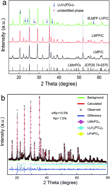 | ||
| Fig. 1 XRD patterns of the as-synthesized composites (a) and Rietveld refinement of 6LMFP·LVP/C (b). | ||
| Sample | a (Å) | b (Å) | c (Å) | Volume (Å3) |
|---|---|---|---|---|
| LMP | 6.0942 | 10.4358 | 4.7487 | 302.01 |
| LMFP | 6.0671 | 10.4262 | 4.7358 | 299.57 |
| 6LMFP·LVP | 6.0558 | 10.4168 | 4.7273 | 298.21 |
Fig. 2a–c show the SEM images of the LMP/C, LMFP/C, and 6LMFP·LVP/C powders. All the samples illustrate similar nanoparticles morphology with the size of ca. 100–150 nm and narrow distribution. The TEM images (Fig. 2d and e) exhibit that the well-dispersed 6LMFP·LVP/C granules are interconnected by the amorphous carbon layer rather than agglomerated into larger blocks. A homogenous carbon layer formed from the pyrolysis of lauric acid is tightly coated on the surface of the 6LMFP·LVP nanoparticles in a thickness of ca. 3 nm. The carbon contents evaluated by elemental analysis are 6.27 wt%, 6.32 wt%, and 6.43 wt% for the LMP/C, LMFP/C, and 6LMFP·LVP/C powders, respectively. The phase compositions of 6LMFP·LVP/C are indicated in the HRTEM image (Fig. 2f). The interplanar spacing of 0.351 and 0.245 nm correspond to the (111) and (211) planes of LiMn0.8Fe0.2PO4, whereas the interplanar spacing of 0.431 nm and 0.220 are attributed to the (020) and (322) planes of Li3V2(PO4)3. The results imply that both LiMn0.8Fe0.2PO4 and Li3V2(PO4)3 phases coexist in the 6LMFP·LVP/C composite particles. The EDS spectrum of 6LMFP·LVP/C (Fig. 2g) displays the characteristic peaks of Mn, Fe, V, P, O, and C. The molar ratio of Mn![[thin space (1/6-em)]](https://www.rsc.org/images/entities/char_2009.gif) :
:![[thin space (1/6-em)]](https://www.rsc.org/images/entities/char_2009.gif) Fe
Fe![[thin space (1/6-em)]](https://www.rsc.org/images/entities/char_2009.gif) :
:![[thin space (1/6-em)]](https://www.rsc.org/images/entities/char_2009.gif) V is 7.28
V is 7.28![[thin space (1/6-em)]](https://www.rsc.org/images/entities/char_2009.gif) :
:![[thin space (1/6-em)]](https://www.rsc.org/images/entities/char_2009.gif) 1.81
1.81![[thin space (1/6-em)]](https://www.rsc.org/images/entities/char_2009.gif) :
:![[thin space (1/6-em)]](https://www.rsc.org/images/entities/char_2009.gif) 3.00, which is basically in accordance with the theoretical ratio of 2.4
3.00, which is basically in accordance with the theoretical ratio of 2.4![[thin space (1/6-em)]](https://www.rsc.org/images/entities/char_2009.gif) :
:![[thin space (1/6-em)]](https://www.rsc.org/images/entities/char_2009.gif) 0.6
0.6![[thin space (1/6-em)]](https://www.rsc.org/images/entities/char_2009.gif) :
:![[thin space (1/6-em)]](https://www.rsc.org/images/entities/char_2009.gif) 1. The chemical composition of 6LMFP·LVP/C was further measured by ICP and is listed in Table 2.
1. The chemical composition of 6LMFP·LVP/C was further measured by ICP and is listed in Table 2.
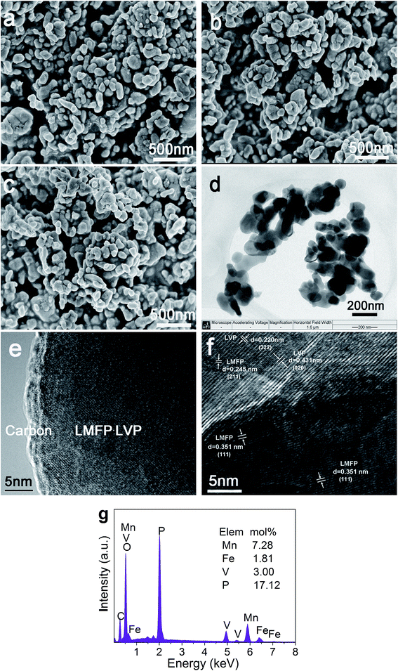 | ||
| Fig. 2 SEM images of LMP/C (a), LMFP/C (b), and 6LMFP·LVP/C (c); TEM images (d and e), HRTEM image (f), and EDS pattern (g) of 6LMFP·LVP/C. | ||
| Element | Molar ratio | |
|---|---|---|
| Theoretical | 6LMFP·LVP/C | |
| Li | 4.5 | 4.63 |
| Mn | 2.4 | 2.43 |
| Fe | 0.6 | 0.58 |
| V | 1 | 1 |
| P | 4.5 | 4.42 |
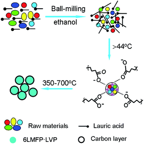
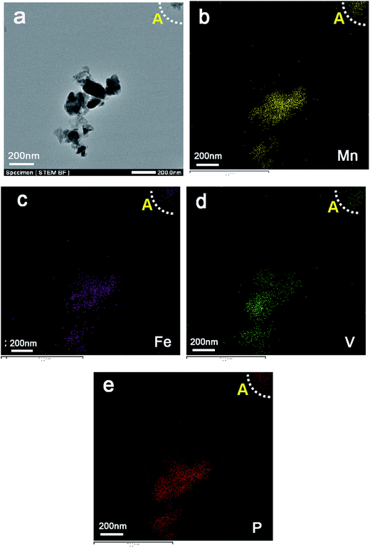
Fig. 3 illustrates the formation procedure of 6LMFP·LVP/C. Lauric acid (CH3(CH2)10COOH) is a saturated fatty acid with a relatively low melting point of 44 °C. During the heating process, lauric acid can form a molten media in which the carboxylic groups of lauric acid conjugate the inorganic cations and the long carbon chains separate the precursors. Thus, the 6LMFP·LVP crystallites can grow in a confined environment. Moreover, the crystallites are enveloped in an in situ conductive carbon layer generated from the decomposition of lauric acid. This effectively restrains the aggregation of the nanoparticles and further growth. Lauric acid, acted as a surfactant and carbon source, is favorable for fabricating granular nanocomposites with good dispersion. The distribution of the elements in 6LMFP·LVP/C was characterized by EDS. As shown in Fig. 4, the elements Mn, Fe, V, and P are homogeneously dispersed in every 6LMFP·LVP/C nanoparticle, such as a particle marked as A. The EDS mappings, together with HRTEM image (Fig. 2f), indicate that the Li3V2(PO4)3 phase uniformly diffuses into the LiMn0.8Fe0.2PO4 matrix, forming a multiphase dispersoid rather than existing as individual LiMn0.8Fe0.2PO4 and Li3V2(PO4)3 particles.
Fig. 5a shows the initial charge–discharge curves of the LMP/C, LMFP/C, and 6LMFP·LVP/C composites. The cells were charged to 4.5 V at 0.1C rate (17 mA g−1), kept at 4.5 V until the current decreased to 0.02C, and then discharged to 2.0 V at 0.1C rate. As observed for LMP/C, a pair of sloping voltage plateaus (4.22/3.93 V) corresponds to the phase transition of LiMnPO4 ↔ MnPO4.1,2 Compared with LMP/C, LMFP/C presents another pair of voltage plateaus (3.62/3.58 V), associating with the phase transition of LiFePO4 ↔ FePO4.9,10 For the 6LMFP·LVP/C sample, three pairs of voltage plateaus (3.59/3.58, 3.68/3.66, 4.08/4.02 V) are assigned to the sequential phase transitions of Li3V2(PO4)3 ↔ Li2.5V2(PO4)3 ↔ Li2V2(PO4)3 ↔ LiV2(PO4)3,32,36,42 respectively. However, the charge plateau of Fe3+/Fe2+ is invisible because of overlapping with the plateau of LixV2(PO4)3 (x from 3 to 2.5). Note that the voltage difference between the charge and discharge plateaus corresponding to LiMnPO4 ↔ MnPO4 decreases when Fe is introduced and further decreases when Li3V2(PO4)3 is introduced, demonstrating smaller polarization and higher electrochemical kinetics. Moreover, the initial discharge capacity reaches 162 mA h g−1 for the 6LMFP·LVP/C sample at 0.1C rate, whereas it reaches 144 mA h g−1 for LMFP/C and 124 mA h g−1 for LMP/C under the same conditions.
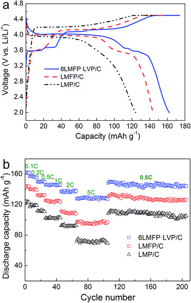 | ||
| Fig. 5 Charge–discharge curves at 0.1C rate (a) and rate capabilities (b) of LMP/C, LMFP/C and 6LMFP·LVP/C. | ||
Fig. 5b exhibits the rate capabilities of the LMP/C, LMFP/C, and 6LMFP·LVP/C composites. Obviously, the rate capability of 6LMFP·LVP/C is superior to those of LMFP/C and LMP/C. The discharge capacities of 6LMFP·LVP/C at 0.5, 1, and 2C rates are 150, 146, and 139 mA h g−1, compared to 133, 125, and 111 mA h g−1 for LMFP/C and 111, 102, and 92 mA h g−1 for LMP/C. Even at 5C, a higher discharge capacity of 128 mA h g−1 for 6LMFP·LVP/C was achieved. The rate performance of the as-prepared 6LMFP·LVP/C nanocomposite exceeded those of the reported LiMn0.8Fe0.2PO4/C,13 0.5LiMnPO4·0.5 Li3V2(PO4)3/C,30 5LiMn0.9Fe0.1PO4·Li3V2(PO4)3/C (ref. 36), and 0.95LiMn0.95Fe0.05PO4·0.05Li3V2(PO4)3/C (ref. 35) composites. The cycling stabilities of LMP/C, LMFP/C, and 6LMFP·LVP/C were characterized at 0.5C after the rate capability test. It can be observed that the discharge capacities of these composites decrease with the increasing C-rate. More importantly, when the discharge rate returns to 0.5C after testing at 5C, the capacities of three composites resumed the former state and faded less than 5% after subsequent 100 cycles, implying high electrochemical reversibility and structural stability for all the samples. The superior high-rate performance of 6LMFP·LVP/C could be attributed to its unique heterogeneous nanostructures. First, the collaborative effect of Fe and V co-doping and the complete conductive carbon coating effectively promote the electrical conductivity in the bulk phase and at the surface, respectively.3 Second, the dispersion of Li3V2(PO4)3 crystallites in the LiMn0.8Fe0.2PO4 matrix reduces the Li+ diffusion pathway in bulk LiMnPO4, which facilitates faster Li-ion intercalation kinetics.
The electrochemical performance of the 6LMFP·LVP/C composite cycled in a wide voltage range of 2.0–4.8 V was also been investigated. Fig. 6a displays the typical charge–discharge curves of 6LMFP·LVP/C at 0.1C and 0.5C. When the end-of-charge voltage extended to 4.8 V, another plateau at 4.52 V in the charge curve was observed, which belonged to the extraction of the third Li+ from Li3V2(PO4)3. The charge and discharge capacities of 6LMFP·LVP/C at the second cycle are 178 and 167 mA h g−1 at 0.1C rate, respectively, with the corresponding coulombic efficiency of 93.8%. At a 0.5C rate, a discharge capacity of 143 mA h g−1 was still achieved, and the capacity retention was as high as 91% at the end of 250 cycles. The slight capacity loss may be induced by the deterioration of the electrode/electrolyte interface, resulting from the electrolyte decomposition at high potential.
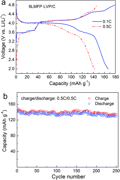 | ||
| Fig. 6 Charge–discharge curves (a) and cycling performance (b) of 6LMFP·LVP/C between 2.0 and 4.8 V. | ||
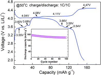
Fig. 7 describes the charge–discharge curve and cycle life (inset) of 6LMFP·LVP/C at 50 °C. In comparison with the charge–discharge curve obtained at room temperature, as shown in Fig. 5a, 6LMFP·LVP/C presents smaller hysteresis between charge and discharge and flatter charge plateau of Mn3+/Mn2+ at elevated temperature. Furthermore, the charge plateaus of Fe3+/Fe2+ (3.55 V) and V5+/V4+ (4.47 V) can be distinctly observed, demonstrating its improved electrode kinetics at high temperature. The 6LMFP·LVP/C delivers a large reversible capacity of 154 mA h g−1 at 1C rate and provides a capacity retention of about 90% over 100 cycles, illustrating a good high-temperature stability of the electrode.
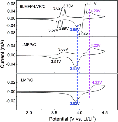
To further clarify the synergistic effects of the solid solution and multiphase composition, cyclic voltammetry was employed to analyze the lithiation/delithiation behavior. Fig. 8 compares the CV curves of LMP/C, LMFP/C, and 6LMFP·LVP/C electrodes at a scan speed of 0.1 mV s−1. One couple peak located at 3.68/3.51 V for LMFP/C and three couple peaks located at 3.62/3.57, 3.70/3.65, and 4.11/4.04 V for 6LMFP·LVP/C are ascribed to the redox of Fe3+/Fe2+ and V4+/V3+, respectively. The peak couples at 4.33/3.92 for LMP/C, 4.23/3.92 for LMFP/C, and 4.20/3.95 V for 6LMFP·LVP/C are associated with the redox of Mn3+/Mn2+. More significantly, the separation potentials between the Mn3+/Mn2+ redox peaks decrease from 0.41 V of LMP/C to 0.31 V of LMFP/C and 0.25 V of 6LMFP·LVP/C. The abovementioned results are in accordance with the charge–discharge curves, which suggest that the electrochemical activity of LiMnPO4 is remarkably enhanced by the appropriate Fe substitution and combination of Li3V2(PO4)3.
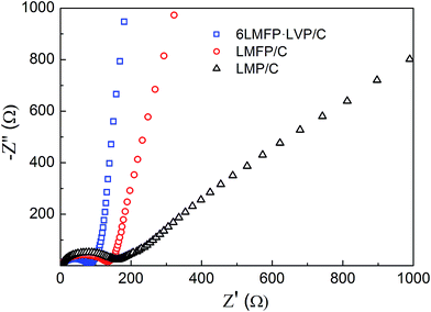
Fig. 9 shows the AC impedance spectra of LMP/C, LMFP/C, and 6LMFP·LVP/C electrodes at the fully discharged state after 100 cycles. All the spectra present a depressed semicircle in the high-medium frequency region, corresponding to the charge-transfer impedance at the electrode/electrolyte interface, and a straight line in the low frequency region, relating to the Li+ diffusion in the electrode material. The slope of the straight line is proportional to the Li+ diffusion coefficient.13,42 By comparing the diameter of the semicircles and the slope of the straight lines, it was found that 6LMFP·LVP/C exhibits smaller interface impedance and much faster Li+ diffusion than LMFP/C and LMP/C. This demonstrates that the electronic and ionic conductivity of 6LMFP·LVP/C are better than those of LMFP/C and LMP/C and also clarifies the fast rate capability of 6LMFP·LVP/C.
4. Conclusions
The 6LiMn0.8Fe0.2PO4·Li3V2(PO4)3/C composite with the size of ca. 100–150 nm was successfully synthesized via a surfactant-assisted solid-state method employing lauric acid as a surfactant and carbon source. The use of lauric acid is beneficial for the fabrication of uniform nanoparticles with high dispersion. XRD and EDS mapping illustrate that the composite consists of LiMn0.8Fe0.2PO4 and Li3V2(PO4)3 phases, and the Li3V2(PO4)3 phase uniformly diffuses into the LiMn0.8Fe0.2PO4 matrix. The 6LiMn0.8Fe0.2PO4·Li3V2(PO4)3/C composite exhibits much higher specific capacity and better rate capability than the individual LiMn0.8Fe0.2PO4/C and LiMnPO4/C. The enhanced electrochemical performance of the multiphase composite demonstrates its use as a promising cathode material for high-power lithium ion batteries.Acknowledgements
This work was supported by the National Natural Science Foundation of China (No. 21401061), Provincial Natural Science Research Foundation of Anhui Universities, China (No. KJ2015A332 and KJ2014A224), Innovation Team of Design and Application of Advanced Energetic Materials and the Key project of Anhui Universities support program for Outstanding Youth, China (No. gxyqZD2016111), Natural Science Foundation of Anhui Province, China (No. 1308085QB41), and the Henan Joint Funds of the National Natural Science Foundation of China (U1504532).References
- S. M. Oh, S. W. Oh, C. S. Yoon, B. Scrosati, K. Amine and Y. K. Sun, Adv. Funct. Mater., 2010, 20, 3260–3265 CrossRef CAS.
- T. Drezen, N.-H. Kwon, P. Bowen, I. Teerlinck, M. Isono and I. Exnar, J. Power Sources, 2007, 174, 949–953 CrossRef CAS.
- C. Hu, H. Yi, H. Fang, B. Yang, Y. Yao, W. Ma and Y. Dai, Electrochem. Commun., 2010, 12, 1784–1787 CrossRef CAS.
- J. Xiong, Y. Wang, Y. Wang and J. Zhang, Ceram. Int., 2016, 42, 9018–9024 CrossRef CAS.
- S. Novikova, S. Yaroslavtsev, V. Rusakov, A. Chekannikov, T. Kulova, A. Skundin and A. Yaroslavtsev, J. Power Sources, 2015, 300, 444–452 CrossRef CAS.
- Y. Hong, Z. Tang, Z. Hong and Z. Zhang, J. Power Sources, 2014, 248, 655–659 CrossRef CAS.
- S. Li, Z. Su, A. Muslim, X. Jiang and X. Wang, Ceram. Int., 2015, 41, 11132–11135 CrossRef CAS.
- R. V. Hagen, H. Lorrmann, K.-C. Möller and S. Mathur, Adv. Energy Mater., 2012, 2, 553–559 CrossRef.
- L. Chen, Y.-Q. Yuan, X. Feng and M.-W. Li, J. Power Sources, 2012, 214, 344–350 CrossRef CAS.
- S.-Y. Yan, C.-Y. Wang, R.-M. Gu, S. Sun and M.-W. Li, J. Alloys Compd., 2015, 628, 471–479 CrossRef CAS.
- F. Ye, L. Wang, X. He, M. Fang, Z. Dai, J. Wang, C. Huang, F. Lian, J. Wang, G. Tian and M. Ouyang, J. Power Sources, 2014, 253, 143–149 CrossRef CAS.
- P. Zuo, G. Cheng, L. Wang, Y. Ma, C. Du, X. Cheng, Z. Wang and G. Yin, J. Power Sources, 2013, 243, 872–879 CrossRef CAS.
- B. Z. Li, Y. Wang, L. Xue, X. P. Li and W. S. Li, J. Power Sources, 2013, 232, 12–16 CrossRef CAS.
- L. Yang, Y. Xia, L. Qin, G. Yuan, B. Qiu, J. Shi and Z. Liu, J. Power Sources, 2016, 304, 293–300 CrossRef CAS.
- L. Yang, Y. Xia, X. Fan, L. Qin, B. Qiu and Z. Liu, Electrochim. Acta, 2016, 191, 200–206 CrossRef CAS.
- Q.-Q. Zou, G.-N. Zhu and Y.-Y. Xia, J. Power Sources, 2012, 206, 222–229 CrossRef CAS.
- J. Liu, W. Liao and A. Yu, J. Alloys Compd., 2014, 587, 133–137 CrossRef CAS.
- Y. P. Huang, T. Tao, Z. Chen, W. Han, Y. Wu, C. Kuang, S. Zhou and Y. Chen, J. Mater. Chem. A, 2014, 2, 18831–18837 CAS.
- C. Xu, L. Li, F. Qiu, C. An, Y. Xu, Y. Wang, Y. Wang, L. Jiao and H. Yuan, J. Energy Chem., 2014, 23, 397–402 CrossRef CAS.
- Z.-X. Chi, W. Zhang, X.-S. Wang, F.-Q. Cheng, J.-T. Chen, A.-M. Cao and L.-J. Wan, J. Mater. Chem. A, 2014, 2, 17359–17365 CAS.
- Y. Mi, P. Gao, W. Liu, W. Zhang and H. Zhou, J. Power Sources, 2014, 267, 459–468 CrossRef CAS.
- W. Liu, P. Gao, Y. Mi, J. Chen, H. Zhou and X. Zhang, J. Mater. Chem. A, 2013, 1, 2411–2417 CAS.
- X. Yang, Y. Mi, W. Zhang, B. Wu and H. Zhou, J. Power Sources, 2015, 275, 823–830 CrossRef CAS.
- W. Yang, Y. Bi, Y. Qin, Y. Liu, X. Zhang, B. Yang, Q. Wu, D. Wang and S. Shi, J. Power Sources, 2015, 275, 785–791 CrossRef CAS.
- W. Xiang, E.-H. Wang, M.-Z. Chen, H.-H. Shen, S.-L. Chou, H. Chen, X.-D. Guo, B.-H. Zhong and X. Wang, Electrochim. Acta, 2015, 178, 353–360 CrossRef CAS.
- C. Gao, H. Liu, G. Liu, J. Zhang and W. Wang, Mater. Sci. Eng., B, 2013, 178, 272–276 CrossRef CAS.
- Y. Guo, Y. Huang, D. Jia, X. Wang, N. Sharma, Z. Guo and X. Tang, J. Power Sources, 2014, 246, 912–917 CrossRef CAS.
- J.-f. Zhang, C. Shen, B. Zhang, J.-c. Zheng, C.-l. Peng, X.-w. Wang, X.-b. Yuan, H. Li and G.-m. Chen, J. Power Sources, 2014, 267, 227–234 CrossRef CAS.
- B. Zhang, X.-w. Wang and J.-f. Zhang, RSC Adv., 2014, 4, 49123–49127 RSC.
- S. Li, Z. Su and X. Wang, RSC Adv., 2015, 5, 80170–80175 RSC.
- F. Wang, J. Yang, Y. NuLi and J. Wang, Electrochim. Acta, 2013, 103, 96–102 CrossRef CAS.
- C. Wang, Y. Bi, Y. Liu, Y. Qin, Y. Fang and D. Wang, J. Power Sources, 2014, 263, 332–337 CrossRef CAS.
- S. Zhong, L. Wu, J. Zheng and J. Liu, Powder Technol., 2012, 219, 45–48 CrossRef CAS.
- L. Qin, Y. Xia, B. Qiu, H. Cao, Y. Liu and Z. Liu, J. Power Sources, 2013, 239, 144–150 CrossRef CAS.
- L. Chen, B. Yan, H. Wang, X. Jiang and G. Yang, J. Power Sources, 2015, 287, 316–322 CrossRef CAS.
- L. Wu, J. Lu, G. Wei, P. Wang, H. Ding, J. Zheng, X. Li and S. Zhong, Electrochim. Acta, 2014, 146, 288–294 CrossRef CAS.
- X. Zhou, Y. Xie, Y. Deng, X. Qin and G. Chen, J. Mater. Chem. A, 2015, 3, 996–1004 CAS.
- L. Zhang, Q. Qu, L. Zhang, J. Li and H. Zheng, J. Mater. Chem. A, 2014, 2, 711–719 CAS.
- M. Secchiaroli, F. Nobili, R. Tossici, G. Giuli and R. Marassi, J. Power Sources, 2015, 275, 792–798 CrossRef.
- Q. Li, F. Zheng, Y. Huang, X. Zhang, Q. Wu, D. Fu, J. Zhang, J. Yin and H. Wang, J. Mater. Chem. A, 2015, 3, 2025–2035 CAS.
- F. Zheng, C. Yang, X. Ji, D. Hu, Y. Chen and M. Liu, J. Power Sources, 2015, 288, 337–344 CrossRef CAS.
- L. Mai, S. Li, Y. Dong, Y. Zhao, Y. Luo and H. Xu, Nanoscale, 2013, 5, 4864–4869 RSC.
| This journal is © The Royal Society of Chemistry 2017 |

