 Open Access Article
Autonomous and complex flow control involving multistep injection and liquid replacement in a reaction chamber on steadily rotating centrifugal microfluidic devices†
Shunya Okamotoa and
Yoshiaki Ukita *b
*b
aDepartment of Engineering, Integrated Graduate School of Medicine, Engineering, and Agricultural Sciences, Graduate School of University of Yamanashi, Japan
bFaculty of Engineering, Graduate Faculty of Interdisciplinary Research, Graduate School of University of Yamanashi, Japan. E-mail: yukita@yamanashi.ac.jp
First published on 19th July 2017
Abstract
This study demonstrates a novel autonomous flow-control technique using siphon-shaped microchannels on a steadily rotating centrifugal microfluidic device. We also develop a simple microfluidic device, which comprises simple casted polydimethylsiloxane, capable of implementing a multistep, timely flow injection, and the replacement of the liquid present in a chamber, without requiring external triggers to switch the flow operation modes. We demonstrate the multistep, timely flow injection system with the steadily rotating, disk-shaped, microfluidic device and the four steps of flow injection. We investigate the effect of surface tension, which affects the liquid replacement error, on the extent of the remaining liquid plug in a siphon-shaped microchannel to realize a stable liquid replacement. We also investigate the liquid behavior in the siphon-shaped microchannels and develop a suitable design to realize autonomous liquid replacement in the reaction chamber, which is required in automatic chemical processes. Moreover, we develop a device capable of implementing the three-step liquid injection process and the liquid replacement in a liquid reservoir, which are potentially applied with a chemical analysis process, such as the enzyme-linked immunosorbent assay.
1. Introduction
Studies on the applications of microfluidic devices in various fields have increased drastically in recent years. Flow control in microfluidic devices plays an important role in executing a series of unit operations. However, controlling pump and valve using peripheral equipment is generally necessary to switch unit operations. Hence, systems have become more complex, larger, and expensive.The use of a centrifugal microfluidic device is one of the simplest methods to pump fluid and realize fluid pumping by rotating a disk-like chip device.1–3 A centrifugal microfluidic device generally employs external triggering mechanisms to switch unit operations, such as laser irradiation on a wax valve4,5 and changing pneumatic pressure via a heating cycle.6,7 Other flow-switching techniques (e.g., water dissolvable film,8,9 hydrocarbon gel valve,10 external air jetting on disk surfaces,11 and magnetic actuation of valves12) have also been proposed. These methods are effective in controlling the flow. However, additional engineering for the integration of dissolvable films and gels or complex custom-made equipment for the control of external triggers is required.
Simpler methods for achieving flow sequencing include switching the rotational frequency, such as capillary valves,13 integrated siphons combined with multiple switching of the rotational frequency for the multistep flow,14 and pneumatic-pressure control combined with the switching of the rotational frequency.15 However, these methods still require sophisticated programmable mechatronic systems for the multistep switching of the rotational frequency. Kinahan et al. developed a logical flow control device based on water dissolvable films.9 The device can execute complex flow control at a steady rotational frequency and can potentially be applied to automate a chemical analysis process, such as the enzyme-linked immunosorbent assay (ELISA). However, the integration of a dissolvable film makes the manufacturing process more complex and may increase the cost.
We previously proposed simple internally triggered flow-sequencing devices16–18 consisting of a single layer of polydimethylsiloxane (PDMS) attached onto a compact disk (CD)-shaped substrate. These studies demonstrated the automatic injection of liquid using a fluidic circuit with water clocks. In the present study, we propose a novel internal sequencing method that can control the timely injection and draining of liquid at steady rotational frequencies for ELISA.
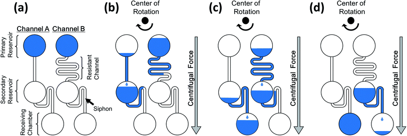
Fig. 1 shows the working principle of the proposed method. The liquid was injected into the secondary reservoir through the resistant channel on the onset of rotation. The liquid was temporarily stored in the reservoir via a siphon-shaped microchannel, and the liquid level gradually increased in the secondary reservoir. The liquid was injected into the receiving chamber when that in the secondary reservoir filled the siphon. The flow rate of the liquid into the secondary reservoir was controlled by adjusting the resistance of each resistant channel to achieve a timely, multistep flow injection. Therefore, achieving autonomous sequential flow control using the proposed system comprising a single layer of PDMS without requiring external triggering mechanisms is possible. In this study, we demonstrated an autonomous flow-control technique capable of complex liquid sequencing applicable to ELISA based on the proposed principle.
2. Experiments
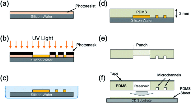
The PDMS microchips were fabricated using the standard soft lithography method.19 Molds with thick negative-photoresist (SU-8, Nippon Kayaku Co., Ltd., Japan) relief patterns were fabricated on a silicon wafer using photolithography. PDMS was applied onto the mold. An SU-8 film with 85 μm thickness was applied to the silicon wafer by spin coating and soft baked at 95 °C (Fig. 2(a)). The photoresist with the patterns of the microchannel and chambers was then exposed to a UV light under a photomask (Fig. 2(b)). The substrate was post-baked at 95 °C and developed (Fig. 2(c)). PDMS was prepared by mixing a PDMS monomer and a catalyst at a ratio of 10![[thin space (1/6-em)]](https://www.rsc.org/images/entities/char_2009.gif) :
:![[thin space (1/6-em)]](https://www.rsc.org/images/entities/char_2009.gif) 1 (w
1 (w![[thin space (1/6-em)]](https://www.rsc.org/images/entities/char_2009.gif) :
:![[thin space (1/6-em)]](https://www.rsc.org/images/entities/char_2009.gif) w) and applied onto the mold attached with spacers to adjust the thickness of the PDMS chip at 3 mm (Fig. 2(d)). The PDMS sheet was then peeled from the substrate. Subsequently, the outer shape and the chambers were cut using a knife and punched out (Fig. 2(e)). Surface modification of the microchannel, such as hydrophilic modification using oxygen plasma, was not conducted. The PDMS microchips were cleaned with ion-exchanged water and ethanol under ultrasonic waves. Another PDMS film with 0.5 mm thickness was attached to a 12 cm CD substrate after drying in a vacuum chamber for 90 min. The microchips were bonded onto the film to seal the fluidic structure and form a closed microchannel structure via the self adhesion of the PDMS to obtain a centrifugal device (Fig. 2(f)).
w) and applied onto the mold attached with spacers to adjust the thickness of the PDMS chip at 3 mm (Fig. 2(d)). The PDMS sheet was then peeled from the substrate. Subsequently, the outer shape and the chambers were cut using a knife and punched out (Fig. 2(e)). Surface modification of the microchannel, such as hydrophilic modification using oxygen plasma, was not conducted. The PDMS microchips were cleaned with ion-exchanged water and ethanol under ultrasonic waves. Another PDMS film with 0.5 mm thickness was attached to a 12 cm CD substrate after drying in a vacuum chamber for 90 min. The microchips were bonded onto the film to seal the fluidic structure and form a closed microchannel structure via the self adhesion of the PDMS to obtain a centrifugal device (Fig. 2(f)).
Each chamber of the PDMS microchip device was covered with adhesive tape. Stained water with dissolved Victoria Blue B (Wako Pure Chemical Industries, Ltd., Japan) in ion-exchanged water with 0.2% (w/v) content was used to visualize the flow better. Moreover, 50 μL water was applied in each primary reservoir using a micropipette. The device was then mounted on a spinning apparatus developed in the laboratory20 and accelerated to 1500 rpm s−1 up to a rotational frequency, which was preferred for driving of the device and subsequently maintained. A stroboscope21 was used to observe the behavior of the liquid in real time.
3. Results and discussion
3.1. Demonstration of the autonomous flow sequencing
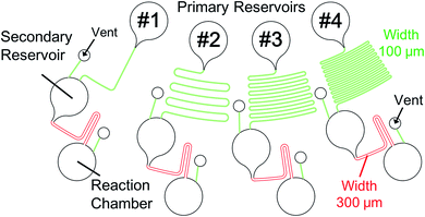
Fig. 3 shows the structure of the device designed based on the proposed concept. Four different types of microchannels were patterned on the device. The differences between the microchannels were only in the length of the resistant channels. The formula developed by Duffy et al. was employed to estimate the timing of injection.22 The width of the microchannels at the siphon part was 300 μm (colored in red), while that of the other was 100 μm (colored in green). Fig. 4 and ESI Movie I† present the series of observed flow behavior. Fig. 4(a) shows the images of the flow sequencing implemented at a constant rotational frequency of 1500 rpm. The applied liquid retained in the primary reservoir started flowing into the resistant channels when the device started spinning. The capillary action of the liquid was not observed because the microchannel was hydrophobic. We confirmed from Fig. 4(a) that the liquid was injected into the reaction chamber in the order of length or flow resistant of the resistant channel. The interval time between the beginning of rotation and the starting of injection was measured and defined to be the sequencing time. Triplicated experiments at 1500 rpm were performed. The average and the standard deviation of the sequencing times were then calculated. The experiment results showed that errors (e.g., shuffling of injection order) did not occur, and the reproducibility was high. The experimental flow rate in the resistant channels was 1.2 times faster than the theoretical value because of the mismatch of the viscosities between the design and the experiment. While the viscosity at 20 °C was employed for the device design, the ambient temperature during the experiments was typically higher, thereby resulting in a lower fluid viscosity. Therefore, controlling the temperature is important in achieving a higher control precision. The coefficient of variation (CV) of the sequencing time was in the 3.01–6.19% range. Therefore, the effect of the error was found to be minor in terms of the result of the assay based on our experience. Moreover, a dependency on the rotational frequency was confirmed by changing the operation rotational frequency (900–2000 rpm) and measuring each sequencing time (Fig. 4(b)). We also performed a similar experiment while using the device with a narrower siphon width of 100 μm. In this case, the CV ranged from 7.81 to 14.3%. This result suggested that the narrower microchannel caused the instability of the property because it was more sensitive to the surface tension of the liquid. This sensitivity caused a higher fluctuation of the injection characteristic of the device because the surface tension was affected by many parameters, such as wettability, temperature, and humidity.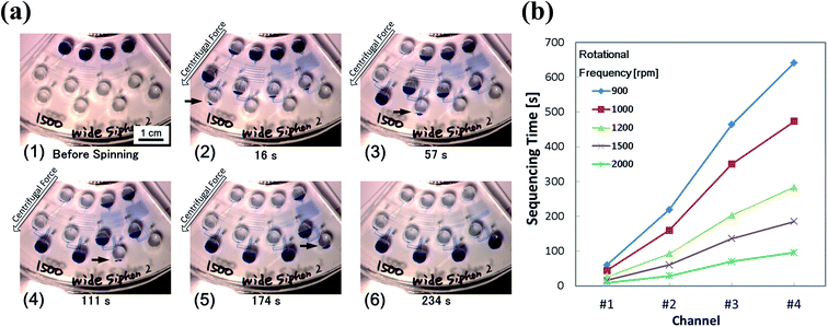 | ||
| Fig. 4 Result of the demonstrating experiment for the proposed method. (a) Step-by-step images of the flow sequencing: (1) initial states; (2) the liquid in channel #1 with the shortest resistant channel is injected into the reaction chamber; (3–5) the liquid is injected into each reaction chamber based on the order of length of the resistant channel; and (6) flow sequencing is completed. (b) Measured sequencing time in each rotational frequency. The video still of the series of flow behavior is available as ESI Movie I.† | ||
3.2. Multistep flow control involving liquid replacement
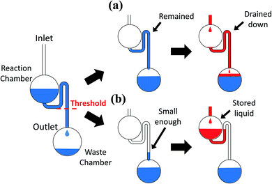
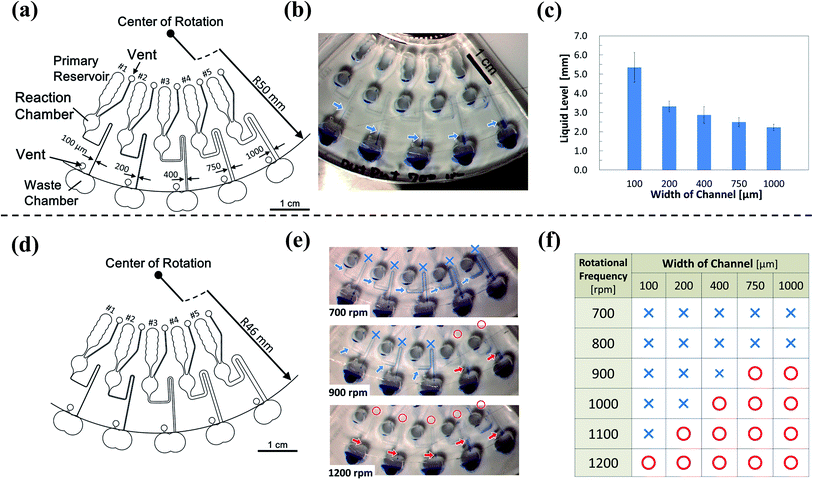
The device must control not only the injection, but also the liquid replacement to perform a chemical analysis, such as ELISA. To replenish the liquid in the reaction chamber after draining it, the liquid must not fill up the siphon after it drains from the reaction chamber (Fig. 5). The liquid, which was subsequently injected from upstream, was drained down to the waste chamber without incubation in the reaction chamber if the liquid remained in the siphon (Fig. 5(a)). The liquid might remain in the siphon because of the surface tension effect. We assumed that the remaining liquid level depended on the equilibrium between the head pressure and the surface tension. We also assumed that the liquid has drained sufficiently from the siphon if the level of the remaining liquid was sufficiently low, and the subsequent liquid injected into the reaction chamber can be stored (Fig. 5(b)). We confirmed this hypothesis by fabricating devices of different widths and lengths of the siphon microchannel (Fig. 6(a) and (d)). We verified the extent to which high liquid levels remain in each microchannel after draining from the siphon. The remaining liquid level decreased with the increase in the width of the microchannel from the experiment conducted at a rotational frequency of 700 rpm (Fig. 6(b) and (c)). We also conducted experiments on a device with a shorter siphon, in which the waste chambers were located 4 mm closer to the center of the rotation (Fig. 6(d)). In this case, the liquid was never drained from all the channels even when the device was spun at 700 rpm. Consequently, draining the liquid from the siphon microchannel cannot be properly implemented if the length of the siphon microchannel is not sufficiently large compared to the remaining liquid level because the meniscus cannot reach below the threshold level indicated in Fig. 5. We conducted experiments with higher rotational frequencies. Although the liquid remained in all the microchannels for speeds lower than 800 rpm, a trend was clearly observed, wherein the liquid was properly drained from the siphon with the increase in the width of the siphon microchannel (lower surface tension) and rotational frequency (Fig. 6(e) and (f)). Hence, the abovementioned hypothesis regarding the liquid draining from the siphon microchannel was successfully proven.A device capable of executing complex multistep flow control, including liquid replacement, was designed and fabricated based on the knowledge gained from these investigations (Fig. 7(a)). Channel #1 was directly connected to the reaction chamber. Channel #2 was connected to the reaction chamber via the resistant channel, secondary reservoir, and siphon. The structure of channel #3 was the same as that of #2, but the length of the resistant channel was greater than that of #2 to have a greater injection-timing delay. The siphon was connected downstream of the reaction chamber for storing and replacing the liquid. Fig. 7(b) and ESI Movie II† show the series of observed flow behavior. The liquid from #1 was injected into the reaction chamber at the onset of rotation. The liquid was injected from #2 after it was stored in the reaction chamber for a while. The reaction chamber was then gradually filled, and the liquid in the reaction chamber started to drain. Hence, the reaction chamber flushed once. Thereafter, the liquid was injected into the reaction chamber from #3 and stored in the reaction chamber without draining it to the waste chamber, successfully completing the replacement. Fig. 7(c) shows the sequencing time of each implemented step. The execution of the designed flow control was implemented via steady rotation without the aid of an external trigger and had a 100% success rate for rotational frequencies more than 1000 rpm up to 1300 rpm (1300 rpm (n = 3) and 1000–1200 rpm (n = 10)). However, the sequencing became unstable at 1000 rpm, and the success rate decreased to 20% at 900 rpm. The error was believed to increase, and the device operation became unstable because the capillary force was relatively more influential at the lower rotational frequencies.
 | ||
| Fig. 7 (a) Schematic of the device used to execute the multistep flow-injection control and the liquid replacement. (b) Progress of the liquid behavior. The video still of the series of the flow behavior is available as ESI Movie II.† (c) Measured sequencing time indicating the time required until the injection of liquid from the start of the rotation in each channel (#1 to #3). | ||
4. Conclusions
We proposed and demonstrated a novel autonomous flow-sequencing concept for a steadily spinning centrifugal microfluidic device. The concept of the multistep liquid injection was successfully demonstrated. Moreover, we not only achieved a controlled injection of the liquid, but also managed to replace the liquid in the reaction chamber at a steadily rotating condition. The developed devices stably executed the liquid replacement. Hence, the method can be applied to the autonomous control of chemical analysis processes, such as ELISA, which require complex flow control. This device is able to execute flow control at steady rotational frequencies. Therefore, the concept involved is believed to contribute to the reduction of the technical effort required to develop a device-driving system, and the device can even be driven with an existing cheap centrifugal machine. Hence, the proposed concept is promising for the realization of a widespread usage of microfluidic analytical systems.Acknowledgements
This research was supported by the Strategic Information and Communications R&D Promotion Programme (SCOPE) #142103012 of the Japanese Ministry of International Affair and Communications.References
- R. Gorkin, J. Park, J. Siegrist, M. Amasia, B. S. Lee, J. M. Park, J. Kim, H. Kim, M. Madouab and Y. K. Cho, Centrifugal microfluidics for biomedical applications, Lab Chip, 2010, 10, 1758–1773 RSC.
- O. Strohmeier, M. Keller, F. Schwemmer, S. Zehnle, D. Mark, F. von Stetten, R. Zengerleabc and N. Paust, Centrifugal microfluidic platforms: advanced unit operations and applications, Chem. Soc. Rev., 2015, 44, 6187–6229 RSC.
- M. Tang, G. Wang, S. K. Kong and H. P. Ho, A review of biomedical centrifugal microfluidic platforms, Micromachines, 2016, 7, 26 CrossRef.
- T. H. Kim, J. Park, C. J. Kim and Y. K. Cho, Fully integrated lab-on-a-disc for nucleic acid analysis of food-borne pathogens, Anal. Chem., 2014, 86, 3841–3848 CrossRef CAS PubMed.
- K. A. Samra, R. Hanson, M. Madou and R. A. Gorkin III, Infrared controlled waxes for liquid handling and storage on a CD microfluidic platform, Lab Chip, 2011, 11, 723–726 RSC.
- W. A. Faqheria, F. Ibrahima, T. H. G. Thioa, M. M. Aeinehvanda, H. Arofb and M. Madoua, Development of novel passive check valves for the microfluidic CD platform, Sens. Actuators, A, 2015, 222, 245–254 CrossRef.
- M. Keller, S. Wadle, N. Paust, L. Dreesen, C. Nuese, O. Strohmeier, R. Zengerleabc and F. von Stetten, Centrifugo-thermopneumatic fluid control for valving and aliquoting applied to multiplex real-time PCR on off-the-shelf centrifugal thermocycler, RSC Adv., 2015, 5, 89603–89611 RSC.
- R. Gorkin III, C. E. Nwankire, J. Gaughran, X. Zhang, G. G. Donohoe, M. Rook, R. O'Kennedyac and J. Ducréeab, Centrifugo-pneumatic valving utilizing dissolvable films, Lab Chip, 2012, 12, 2894–2902 RSC.
- D. J. Kinahan, S. M. Kearney, N. Dimov, M. T. Glynnab and J. Ducrée, Event-triggered logical flow control for comprehensive process integration of multi-step assays on centrifugal microfluidic platforms, Lab Chip, 2014, 14, 2249–2258 RSC.
- L. Swayne, A. Kazarine, E. J. Templeton and E. D. Salin, Rapid prototyping of pneumatically actuated hydrocarbon gel valves for centrifugal microfluidic devices, Talanta, 2015, 134, 443–447 CrossRef CAS PubMed.
- M. C. R. Kong and E. D. Salin, Pneumatic flow switching on centrifugal microfluidic platforms in motion, Anal. Chem., 2011, 83, 1148–1151 CrossRef CAS PubMed.
- Z. Cai, J. Xianga, B. Zhang and W. Wanga, A magnetically actuated valve for centrifugal microfluidic applications, Sens. Actuators, B, 2015, 206, 22–29 CrossRef CAS.
- S. Lai, S. Wang, J. Luo, L. J. Lee, S. T. Yang and M. J. Madou, Design of a compact disk-like microfluidic platform for enzyme-linked immunosorbent assay, Anal. Chem., 2004, 76, 1832–1837 CrossRef CAS PubMed.
- J. Siegrist, R. Gorkin, L. Clime, E. Roy, R. Peytavi, H. Kido, M. Bergeron, T. Veres and M. Madou, Serial siphon valving for centrifugal microfluidic platforms, Microfluid. Nanofluid., 2010, 9, 55–63 CrossRef.
- F. Schwemmer, S. Zehnle, D. Mark, F. von Stetten, R. Zengerleabc and N. Paustab, A microfluidic timer for timed valving and pumping in centrifugal microfluidics, Lab Chip, 2015, 15, 1545–1553 RSC.
- Y. Ukita, Y. Takamura and Y. Utsumi, A novel flow sequencing method on centrifugal microfluidic device using “Liquid clock”, 24th International Microprocesses and Nanotechnology Conference (NMC2011), 26P-7-147L Search PubMed.
- Y. Ukita, M. Ishizawa, Y. Takamura and Y. Utsumi, Internally triggered multistep flow sequencers using clepsydra, The 16th International Conference on Miniaturized Systems for Chemistry and Life sciences (μTAS2012) Search PubMed.
- Y. Ukita, Y. Takamura and Y. Utsumi, Water-clock-based autonomous flow sequencing in steadily rotating centrifugal microfluidic device, Sens. Actuators, B, 2015, 220, 180–183 CrossRef CAS.
- D. C. Duffy, J. C. McDonald, O. J. A. Schueller and G. M. Whitesides, Rapid prototyping of microfluidic systems in poly(dimethylsiloxane), Anal. Chem., 1998, 70, 4974–4984 CrossRef CAS PubMed.
- Y. Ukita and Y. Takamura, A new stroboscopic technique for the observation of microscale fluorescent objects on a spinning platform in centrifugal microfluidics, Microfluid. Nanofluid., 2015, 18, 245–252 CrossRef CAS.
- M. Grumann, T. Brenner, C. Beer, R. Zengerle and J. Ducrée, Visualization of flow patterning in highspeed centrifugal microfluidics, Rev. Sci. Instrum., 2005, 76, 025101 CrossRef.
- D. C. Duffy, H. L. Gillis, J. Lin, N. F. Sheppard Jr and G. J. Kellogg, Microfabricated centrifugal microfluidic systems: characterization and multiple enzymatic assays, Anal. Chem., 1998, 71, 4669–4678 CrossRef.
Footnote |
| † Electronic supplementary information (ESI) available. See DOI: 10.1039/c7ra03721j |
| This journal is © The Royal Society of Chemistry 2017 |

