DOI:
10.1039/C7RA03936K
(Paper)
RSC Adv., 2017,
7, 30845-30854
A Z-scheme magnetic recyclable Ag/AgBr@CoFe2O4 photocatalyst with enhanced photocatalytic performance for pollutant and bacterial elimination†
Received
6th April 2017
, Accepted 19th May 2017
First published on 14th June 2017
Abstract
In order to construct a magnetic recyclable photocatalyst with superior photocatalytic performance and stability, Ag/AgBr photocatalysts modified by magnetic CoFe2O4 nanoparticles (NPs) were synthesized via deposition–precipitation followed by a solvothermal process. Such a synthesis strategy allows the even dispersion of CoFe2O4 NPs on the surface of Ag/AgBr. Besides, a Z-scheme photocatalyst with metallic Ag as a solid-state electron mediator was formed, which exhibits excellent photocatalytic activity and stability for photocatalytic degradation of hardly decomposed colorless phenol compounds, namely, endocrine disrupting chemical bisphenol A (BPA) and 4-chlorophenol (4-CP), in an aqueous solution. The results showed that the Ag/AgBr@CoFe2O4 composites not only exhibited enhanced photocatalytic performance but also improved stabilities. More importantly, the photocatalysts could be recycled easily by an external magnetic field. The antibacterial activity of the Ag/AgBr@CoFe2O4 composites have been investigated by eliminating Escherichia coli (E. coli) in water under visible light irradiation, and the results revealed that the Ag/AgBr@CoFe2O4 composites possessed good photocatalytic antibacterial activity. At last, the enhanced photocatalytic mechanisms were discussed by investigating the main reactive species in the photocatalytic process, which revealed that the photo-generated holes (h+) and O2˙− were the main reactive species.
1. Introduction
Catalytic elimination of environmental pollutants from water driven by sunlight has gained considerable popularity in recent years.1–3 The key point of this kind of technology is to find out photocatalysts that possess specific features such as high activity, good recyclability, high stability and efficient recovery.4
Recently, Ag-based photocatalysts, such as Ag/AgX (X = Cl, Br, I),5–7 Ag3PO4,8 Ag3VO4,9 Ag2CO3 (ref. 10) and Ag2WO4,11 have been widely investigated as photocatalysts for the applications of solar energy conversion and environmental remediation. Among various Ag-based materials, AgBr is especially attractive owing to its facility synthesis route, appropriate band gap (∼2.6 eV) as well as excellent photocatalytic activity.12–14 However, there are some crucial difficulties in the practical applications of Ag/AgBr, including the photocorrosion problem that occurs under light irradiation and the challenges of the suspended particulate catalyst collection in the photocatalytic separation process.15–17 To overcome these obstacles, two major challenges are faced. Firstly, inhibit or decrease the decomposition of Ag/AgBr under light irradiation. Coupling with other semiconductor support materials to construct a heterojunction structure can increase the stability of Ag/AgBr if transferring or quenching photogenerated electrons on Ag/AgBr instead of unceasingly reducing Ag+ ions in Ag/AgBr to Ag metal.18 The construction of a Z-scheme photocatalytic system in the present Ag/AgBr should come as the first choice strategy because the in situ reduced metallic Ag could act as an electron mediator. A Z-scheme system is typically constructed of two photocatalysts with/without an electron mediator, where the semiconductors are in the form of staggered alignment of band structures. In the Z-scheme, the photogenerated electrons from one of the semiconductors with a lower CB edge would recombine with the holes from another semiconductor with a higher VB edge, thereby leaving electrons and holes on the respective semiconductor. This constitutes an overall redox reaction. In addition, for an efficient Z-scheme photocatalyst system, the balance of catalytic rates for the two semiconductors is very important to the overall photocatalytic reaction. Therefore, a solid electron mediator will be more favorable on the basis of the recovery of the photocatalyst.19 Up to now, many different Ag/AgBr-based Z-scheme photocatalytic systems have been constructed so as to improve the stability and photocatalytic performance of Ag/AgBr, such as AgBr/Ag/BiOBr,20 Ag–AgBr@Bi20TiO32,21 g-C3N4/Ag/Ag2WO4,22 Cu2O/Cu/AgBr/Ag23 and AgBr/Ag/Fe2O3.24 The above research findings indicate that the photocatalytic activity as well as the stability of Ag/AgBr could be significantly enhanced by coupling with a suitable supporting material. Secondly, it is important and urgent to find out an appropriate approach to recycle the photocatalysts. Incorporating Ag/AgBr nanoparticles (NPs) with magnetic materials to address the recyclability problem is a worthwhile strategy. For example, Tian et al.25 prepared a core–shell γ-Fe2O3@SiO2@AgBr:Ag plasmonic photocatalyst. This kind of photocatalyst showed high activity for the photodegradation of acid orange 7 and it could be easily recovered due to its paramagnetic properties. However, grafting AgBr onto SiO2 did not to improve its stability. It is, therefore, necessary to find new ways to overcome the obstacles faced by AgBr photocatalysts.
Spinel cobalt ferrite (CoFe2O4) NPs, which have large saturation magnetization, remarkable mechanical hardness, good chemical stability, low cost and environmental friendliness, have been employed in many fields such as active materials for batteries,26–30 biomedicinal devices and magnetically recoverable catalyst supports.4 Recently, CoFe2O4 has been applied in photocatalyst fields due to its narrow band gap of 1.3 eV and its strong adsorption characteristics in the ultraviolet and visible light regions. Like CoFe2O4–graphene,31,32 CoFe2O4–ZnS,33 CoFe2O4–TiO2,34 CoFe2O4/Ag3PO4 (ref. 35) and CoFe2O4–PANI36 have been prepared and identified to improve photocatalytic activity. In addition, the employment of CoFe2O4 as a component of photocatalysts makes this kind of composite photocatalyst easily recoverable by a magnetic field. Furthermore, as mentioned above, semiconductors with a staggered alignment of band structures coupled together may form a Z-scheme photocatalytic system, which can overcome the obstacles of AgBr as well as yield highly efficient photocatalysts.
Herein, first, we evenly decorated CoFe2O4 NPs on the surface of AgBr via deposition–precipitation and then reduced a part of metallic Ag in the Ag/AgBr@CoFe2O4 composites by a facile solvothermal process. The metallic Ag NPs can act as the charge transmission bridge between AgBr and CoFe2O4, yielding a Z-scheme system. This Z-schematic photocatalyst composite consists of three components: a reduction reaction photocatalyst, an electron mediator and an oxidation reaction photocatalyst, just like the reports of the Au electron mediator in the SrTiO3:La,Rh/Au/BiVO4:Mo system for water splitting, as described by Domen et al.37 The present Ag/AgBr@CoFe2O4 Z-schematic photocatalyst composite exhibited superior photocatalytic performance over the degradation of hardly decomposed colorless phenol compounds (BPA and 4-CP). In addition, because of the quenching of electrons generated on the conduction band (CB) of AgBr, the stabilities of Ag/AgBr@CoFe2O4 composites have been greatly improved. Moreover, CoFe2O4 materials have a strong magnetic property, so that Ag/AgBr@CoFe2O4 composite photocatalysts could be easily recovered from a solution after a photocatalytic reaction. The photocatalytic antibacterial activity of the Ag/AgBr@CoFe2O4 composite was evaluated. This work may open a new insight into the construction of highly efficient and easily recoverable photocatalysts.
2. Experimental
2.1. Materials
All the reagents were purchased from Sinopharm Chemical Reagent Co., Ltd., which were of analytical grade and used without further purification.
2.2. Synthesis of photocatalysis
Preparation of CoFe2O4 NPs:CoFe2O4 NPs were prepared via a sol–gel method reported in our previous work.38
Fabrication of Ag/AgBr-core@CoFe2O4-shell structure: in the typical synthesis of Ag/AgBr@CoFe2O4 composites, firstly, 100 mL ethylene glycol (EG) and 100 mL deionized water were mixed together to form a homogeneous solution (named as solution A). Secondly, CoFe2O4 NPs were dispersed in 30 mL solution A with vigorous mechanical stirring; then, a certain amount of AgNO3 was added. After further stirring for 30 min, NaBr solution was added to the above solution drop by drop and it was kept stirring for another 60 min under 15 °C. Subsequently, the suspensions were transferred to several 25 mL Teflon-lined stainless-steel autoclaves and kept at 140 °C for 20 h. After cooling, the as-prepared photocatalysts were collected and washed with deionized water and ethanol. The photocatalysts were dried under 60 °C overnight. The added contents of CoFe2O4 NPs in the Ag/AgBr@CoFe2O4 composites were adjusted by simply controlling the weight ratio of CoFe2O4 to AgNO3. The final products were named as 10% AgBr@CoFe2O4, 15% Ag/AgBr@CoFe2O4 and 20% Ag/AgBr@CoFe2O4 composite. The detailed material input mass and ratio are listed in Table S1.†
2.3. Photocatalytic activity evaluation
The photocatalytic activities of the as-prepared photocatalysts were assessed by the photodecomposition of phenol compounds, bisphenol A (BPA) and 4-chlorophenol (4-CP), in an aqueous solution under visible light irradiation (300 W xenon lamp, λ > 420 nm). Typically, 0.07 g photocatalysts were dispersed in 70 mL 4-CP (10 mg L−1) or BPA (10 mg L−1) solution. Then, the suspensions were magnetically stirred for 30 min in the dark to get adsorption–desorption equilibrium. Approximately 4 mL of the suspension was collected and filtered through a Millipore filter (pore size of 0.22 μm) to remove the catalysts at regular intervals. The BPA degradation products were analyzed by a UV-vis spectrophotometer (Shimadzu, UV-2450) and an Agilent TC-C18 column, which were equipped with two Varian ProStar 210 pumps and a Varian ProStar 325 UV-vis detector at 230 nm. The remaining concentrations of 4-CP were reflected by a UV-vis spectrophotometer (Shimadzu, UV-2450) at 225 nm.
2.4. Disinfection activity measurement
The antibacterial activities of Ag/AgBr@CoFe2O4 composites were evaluated by killing Escherichia coli (E. coli) bacteria. All the glassware used in the disinfection experiments were sterilized by autoclaving at 121 °C for 20 min. After that, the whole experiment was operated under sterile conditions. For the photocatalysis antibacterial experiments, 5 mg as-prepared 15% Ag/AgBr@CoFe2O4 photocatalysts were suspended in 20 mL sterilized saline solution containing 1 × 10⁷ cfu mL−1 bacteria concentration. The reaction suspensions were stirred in dark for 30 min to establish adsorption–desorption equilibrium prior to the treatment. In the photocatalytic disinfection treatment, 100 μL of the solution was sampled and serially diluted with a sterilized saline solution, then dispersed on a nutrient agar medium, followed by incubation at 37 °C for 16 h in the dark.
3. Results and discussion
3.1. Formation of Ag/AgBr-core@CoFe2O4-shell structure
Scheme 1 displays the design and preparation process of Ag/AgBr@CoFe2O4 composites. The as-prepared CoFe2O4 NPs are granular-like with a narrow particle size distribution of 12.0 ± 2 nm. (The microscopic morphology and size distribution histogram with Gaussian-fitting curve of the as-prepared CoFe2O4 are shown in Fig. S1A and B,† respectively.) Further, the zeta position of the as-prepared CoFe2O4 in the EG/H2O solution was estimated to be −1.08 mV (Fig. S1C†), indicating that its surface has negative polarity in the EG/H2O solution. Therefore, when AgNO3 was added into the solution, the ionized Ag+ could strongly absorb on the surface of CoFe2O4 NPs. After the Br− was dropped in the solution, the CoFe2O4 NPs were attached on the surface of the AgBr particles with Ag+ to form the AgBr-core@CoFe2O4-shell structure. The subsequent solvothermal process allowed the reduction Ag+ ions on the surface of AgBr by means of the EG/H2O solution.12
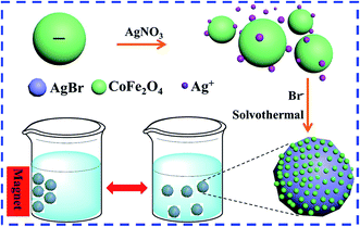 |
| | Scheme 1 Schematic illustration of the synthetic processing of Ag/AgBr@CoFe2O4 composites. | |
3.2. X-ray diffraction (XRD) analysis
The purity and crystallinity of the as-prepared samples were investigated by XRD. The XRD peaks of AgBr (marked with “▽”), CoFe2O4 (marked with “#”) and the as-prepared Ag/AgBr@CoFe2O4 composites are displayed in Fig. 1, which reveals the presence of spinel-type CoFe2O4 (JCPDS card no. 22-1086) and cubic-phase AgBr (JCPDS card no. 06-0438).13,39 The XRD patterns of these as-synthesized Ag/AgBr@CoFe2O4 composites (Fig. 1b–d) are similar to Ag/AgBr (Fig. 1a), but show a small difference in the reflection position at 2θ = 35.2° when the CoFe2O4 content was increased to 15% and 20%. The peak appearing at 2θ = 35.2° belongs to the (311) plane of CoFe2O4, which indicates that CoFe2O4 was not incorporated into the lattice of AgBr. In addition, it is noteworthy that the peaks at 2θ = 35.2° in the Ag/AgBr@CoFe2O4 composites are very weak, suggesting that the CoFe2O4 NPs were well dispersed in the composites. The XRD results also confirmed the formation of Ag/AgBr@CoFe2O4 composites and the conjectured structure was verified by the subsequent SEM, EDS and XPS analyses.
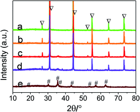 |
| | Fig. 1 XRD patterns of as-prepared samples: (a) pure Ag/AgBr, (b) 10% Ag/AgBr@CoFe2O4, (c) 15% Ag/AgBr@CoFe2O4, (d) 20% Ag/AgBr@CoFe2O4, (e) CoFe2O4. | |
3.3. Structural and component analyses
Fig. 2 shows the SEM images of pure Ag/AgBr and 15% Ag/AgBr@CoFe2O4 composite. It can be seen that pure Ag/AgBr (Fig. 2A) has irregular sphere-like particles having big size (with an average diameter of ca. 3–10 μm) and are seriously aggregated. Upon close observation (Fig. 2B), the surface of the Ag/AgBr particles appears to be very smooth. When compared with pure Ag/AgBr, the SEM images of 15% Ag/AgBr@CoFe2O4 composite particles (Fig. 2C) displayed a rougher surface and no aggregation of CoFe2O4 NPs can be observed, which verified the effective dispersion of CoFe2O4 NPs in the composites. The enlargement of the selected area (Fig. 2D) revealed that CoFe2O4 NPs were evenly attached to the surface of Ag/AgBr and, hence, formed a discontinuous shell on the surface of the Ag/AgBr particles; this can be further confirmed by XPS analysis. As shown in Fig. 3, the survey spectra (Fig. S2A†) clearly showed that Ag, Br, Fe, Co, O and C exist in the composites (C element is from the XPS instrument itself), which is in accordance with the constituent elements of the Ag/AgBr@CoFe2O4 composite. From the high-resolution XPS spectra of Ag 3d and Br 3d, as shown in Fig. 3A and B, respectively, it can be seen that when compared to pure Ag/AgBr, Ag 3d and Br 3d peaks at 15% Ag/AgBr@CoFe2O4 composite show a notable negative shift (about 0.4 eV). The negative shift for Ag 3d and Br 3d in the composites suggests that the interaction between Ag/AgBr and CoFe2O4 NPs was formed.40 Furthermore, it is obvious that the peak intensities of Ag 3d and Br 3d in the Ag/AgBr@CoFe2O4 composites are lower than that of pure Ag/AgBr. It should be considered that the XPS signals were mainly collected from the surface of the sample with a depth of less than 10 nm, which is another indication of the formation of the Ag/AgBr-core/CoFe2O4-shell structure.41
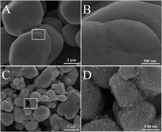 |
| | Fig. 2 SEM images of as-prepared samples: (A) and (B) pure Ag/AgBr; (C) and (D) 15% Ag/AgBr@CoFe2O4 composite. | |
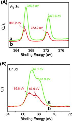 |
| | Fig. 3 XPS spectra of the as-prepared photocatalysts: (A) Ag 3d and (B) Br 3d of (a) Ag/AgBr and (b) 15% Ag/AgBr@CoFe2O4 composite. | |
3.4. Vibrating sample magnetometer analysis
Fig. 4A shows the magnetization curves of pure CoFe2O4 and 15% Ag/AgBr@CoFe2O4, which were measured at room temperature. The hysteresis loop of CoFe2O4 exhibits characteristic ferrimagnetic features42 with saturation magnetization (Ms) of 29.4 emu g−1, remnant magnetization (Mr) of 2.3 emu g−1 and coercivity (Hc) of 199.7 Oe. These indicate that the as-prepared CoFe2O4 possesses good magnetic abilities. The hysteresis loop of Ag/AgBr@CoFe2O4 composites show similar ferrimagnetic behaviors as that of CoFe2O4: the value of Ms, Mr and Hc are 5.5 emu g−1, 0.54 emu g−1 and 199.8 Oe, respectively, for 15% Ag/AgBr@CoFe2O4 composite. The decreased Ms and Mr of the Ag/AgBr@CoFe2O4 composites may be due to the contribution of the nonmagnetic Ag/AgBr to the total mass of the particles.36 It is clear that the Hc values of CoFe2O4 and Ag/AgBr@CoFe2O4 composites are around 199.6 Oe without any considerable difference, as shown in the inset. This suggests that Ag/AgBr@CoFe2O4 composites inherited the magnetism of CoFe2O4, which means the as-prepared Ag/AgBr@CoFe2O4 composite photocatalysts could be recollected by an external magnetic field. Fig. 4B shows a digital photo of the Ag/AgBr@CoFe2O4 composites separated from water under an external magnetic field. Evidently, the photocatalyst particles were attracted toward the magnet within a short period of time.
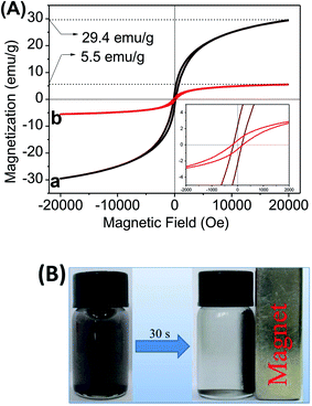 |
| | Fig. 4 (A) Magnetization curves of the as-prepared samples: (a) pure CoFe2O4, (b) 15% Ag/AgBr@CoFe2O4 composites. (B) A digital photo of 15% Ag/AgBr@CoFe2O4 composites separated from water under an external magnetic field. | |
3.5. UV-vis diffuse reflection spectra (DRS) analysis
UV-vis DRS are presented to determine the optical properties of the as-prepared samples. Fig. 5 displays the DRS of Ag/AgBr and Ag/AgBr@CoFe2O4 composites. Ag/AgBr exhibits two main absorption regions: the first one (from 200 to 460 nm) is attributed to the intrinsic absorption of AgBr and the second enhanced absorptions around 500–600 nm are attributed to the plasmon resonance absorptions induced by Ag NPs,12,43 which is indirect evidence of metallic Ag existing in the Ag/AgBr samples. For these Ag/AgBr@CoFe2O4 composites, as the CoFe2O4 content increases, the absorption abilities of Ag/AgBr@CoFe2O4 composites for visible light also increase. The enhanced light absorption ability may result in generating more photoexcited electron–hole pairs, which is beneficial to the photocatalytic activity. However, more CoFe2O4 NPs on the surface of Ag/AgBr will make it difficult for the Ag/AgBr to absorb visible light, leading to lower photocatalytic activity.44
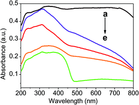 |
| | Fig. 5 The UV-vis absorption spectra of the as-prepared photocatalysts: (a) CoFe2O4, (b) 20% Ag/AgBr@CoFe2O4, (c) 15% Ag/AgBr@CoFe2O4, (d) 10% Ag/AgBr@CoFe2O4, (e) Ag/AgBr. | |
3.6. Photocatalytic performance
Colorless phenol compounds, BPA and 4-CP, were employed as the substrate to evaluate the photocatalytic activities in which photosensitization can be eliminated.45 Fig. 6A shows the photocatalytic performance of Ag/AgBr@CoFe2O4 composites toward BPA degradation. A blank experiment indicates that BPA cannot self-decompose, and dark absorption experiments imply that BPA was rarely absorbed on the surface of Ag/AgBr and Ag/AgBr@CoFe2O4 composites. After turning on the light, BPA decomposed quickly. The BPA degradation percentages in the presence of pure Ag/AgBr, 10% Ag/AgBr@CoFe2O4, 15% Ag/AgBr@CoFe2O4 and 20% Ag/AgBr@CoFe2O4 composites were 40.2%, 59.2%, 73.9% and 66.7% within 120 min, respectively. It can be noted that the photocatalytic activity of Ag/AgBr was greatly improved by introducing CoFe2O4 NPs, which is gradually increased by increasing the CoFe2O4 content. When the content is 15%, the composite displayed the best photocatalytic performance. However, further increasing the content of CoFe2O4, the photocatalytic activity of the Ag/AgBr@CoFe2O4 composite decreased. According to the SEM analysis, the CoFe2O4 NPs were attached on the surface of AgBr. An excess of CoFe2O4 NPs may shield AgBr from light absorption, thereby decreasing the photocatalytic performance. The high performance liquid chromatography (HPLC) analyses of the BPA solution in the absence and presence of 15% Ag/AgBr@CoFe2O4 after irradiating for 120 min are shown in Fig. S5.† Fig. 6B shows the photocatalytic degradation percentage of pure Ag/AgBr and 15% Ag/AgBr@CoFe2O4 composite over 4-CP degradation. It can be seen that when no catalyst is involved in the reaction system, negligible photolysis of 4-CP pollutants could be observed under visible-light irradiation, demonstrating that 4-CP is chemically stable. On the other hand, in the presence of Ag/AgBr and 15% Ag/AgBr@CoFe2O4 composite, the degradation percentage of 4-CP can be observed to be 30.5% (pure Ag/AgBr) and 83.6% (15% Ag/AgBr@CoFe2O4) within 140 min. Further, the 15% Ag/AgBr@CoFe2O4 composite showed much higher photocatalytic activity than that of pure Ag/AgBr. All these results indicate that an appropriate introduction of CoFe2O4 is beneficial for improvements in the photocatalytic performance of Ag/AgBr@CoFe2O4 composites. This improvement may be attributed to the improvement of charge separation efficiency between Ag/AgBr and CoFe2O4, thereby enhancing the photocatalytic activity.
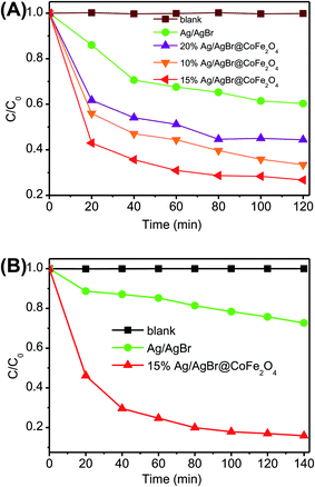 |
| | Fig. 6 (A) Photocatalytic degradation of BPA in the presence of Ag/AgBr and Ag/AgBr@CoFe2O4 composites. (B) A comparison of the photocatalytic activities of Ag/AgBr and 15% Ag/AgBr@CoFe2O4 composites for the degradation of 4-CP. | |
3.7. Electrochemistry analysis
Based on the above experimental results, it is believed that the introduction of CoFe2O4 NPs is favorable for charge separation. In order to prove this assumption, the interfacial charge separation and transfer properties of electrodes were studied by monitoring the photocurrent–time response and electrochemical impedance spectroscopy (EIS) measurements. From Fig. 7A, it is notable that when Ag/AgBr was coupled with CoFe2O4 NPs, the photocurrent responses were greatly enhanced. A higher photocurrent implies better electron–hole separation efficiency and, hence, enhanced photocatalytic activity.46 The radius of the arc on the EIS Nyquist plot can reflect the charge transfer rate between the working electrode and electrolyte solution. A smaller radius of the Nyquist circle means a lower charge-transfer resistance.47,48 The arc radiuses of Ag/AgBr@CoFe2O4 composites are smaller than that of pure Ag/AgBr (Fig. 7B). The EIS measurement results exhibit similar regularity with the photocurrent response described above, indicating that a fast interfacial charge transfer rate was obtained after the CoFe2O4 NPs were loaded onto the surface of Ag/AgBr. The results of the photocurrent responses and EIS measurements indicated that the introduction of CoFe2O4 NPs could improve the separation efficiency of electron–hole pairs and, therefore, could enhance the photocatalytic performance.
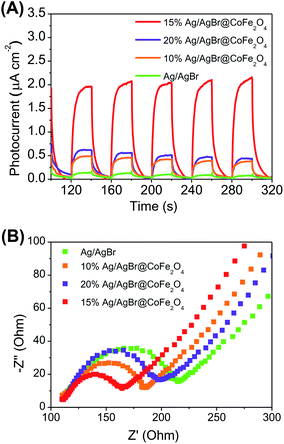 |
| | Fig. 7 (A) Photocurrents of Ag/AgBr and Ag/AgBr@CoFe2O4 composites. (B) Electrochemical impedance spectroscopy of Ag/AgBr and Ag/AgBr@CoFe2O4 composites. | |
3.8. Recycle runs
Fig. 8 presents the cycling runs of pure Ag/AgBr and Ag/AgBr@CoFe2O4 composites in the photodegradation of BPA. It can be found that the degradation efficiency of BPA over the 15% Ag/AgBr@CoFe2O4 composite could still remain at 63.2%, while the BPA degradation efficiency dropped to 1% on pure Ag/AgBr after three recycles, indicating that pure Ag/AgBr possesses very poor recyclability in BPA photodegradation, and the recyclability of Ag/AgBr@CoFe2O4 composite can be improved by coupling with CoFe2O4 NPs. The XRD patterns of 15% Ag/AgBr@CoFe2O4 composite before and after photocatalysis are shown in Fig. S8.† When compared with the pattern of a fresh sample, a weak peak of metallic Ag (2θ = 38.1°) was observed, indicating that the photocorrosion of Ag/AgBr has slowed down. These results demonstrate that the coupling of Ag/AgBr and CoFe2O4 yields excellent photocatalytic performance as well as good stability. The reduction of AgBr stabilities are mainly due to the fact that the photoexcited electrons from AgBr can reduce Ag+ ions to Ag metal, resulting in mass loss in the AgBr photocatalysts and excess Ag metal on the surface would shield AgBr semiconductors from light absorption and pollutant degradation with time.16,49 Therefore, if photogenerated electrons on AgBr are quenched or transferred instead of reducing Ag+ ions in AgBr to Ag metal, the stability of AgBr can increase.18 The introduction of CoFe2O4 NPs could facilitate the transfer and consumption of electrons on the surface of AgBr instead of reducing Ag+ ions in AgBr into Ag metal.
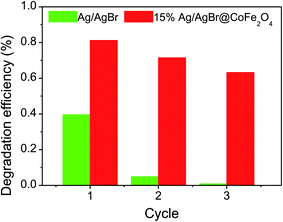 |
| | Fig. 8 Photodegradation efficiencies of BPA over Ag/AgBr and 15% Ag/AgBr@CoFe2O4. | |
3.9. Photocatalytic antibacterial activity
It is reported that millions of people around the world are at risk of illness and even death because their drinking water is infected with harmful bacteria. Therefore, killing harmful bacteria in water is very important.50–53 Herein, the inactivation of E. coli bacteria under visible light with the as-prepared Ag/AgBr@CoFe2O4 composites has been studied, and the results are shown in Fig. 9. Without adding any photocatalysts (Fig. 9A), the amount of E. coli did not obviously decrease under visible light irradiation, implying that E. coli could survive under visible light irradiation. When the 15% Ag/AgBr@CoFe2O4 composite was added (Fig. 9B), the bacterial density did not obviously decrease, suggesting a low toxic effect over the present low composite concentration in the dark (see 15% Ag/AgBr@CoFe2O4 – 0 min); however, the amount of E. coli was gradually decreased when the light was turned on. After irradiating for almost 20 min, no E. coli survived.
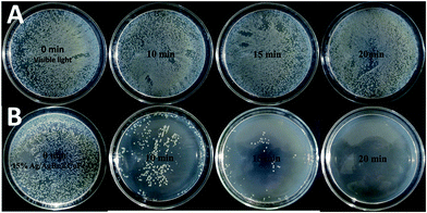 |
| | Fig. 9 Photocatalytic antibacterial activities of (A) light only and (B) 15% Ag/AgBr@CoFe2O4 against E. coli at different irradiation times. | |
3.10. Mechanism discussion
At last, we explored the photocatalytic mechanism of the as-prepared Ag/AgBr@CoFe2O4 composites via a trapping experiment. Here, we employed tert-butanol (t-butanol) and triethanolamine (TEOA) as ˙OH and h+ quenchers, respectively, and used N2-bubbling to inhibit the formation of O2˙−.20 As shown in Fig. 10, the degradation efficiency of BPA can reach up to 81.2% with no quencher. When t-butanol was added, the degradation percentage of BPA still remained at 81.3%, suggesting that ˙OH is not the main reactive species in the photodegradation process of the Ag/AgBr@CoFe2O4 composite. Moreover, the degradation efficiency was decreased under N2 atmosphere and was greatly inhibited by adding TEOA, indicating that h+ was the dominant reactive species and O2˙− played a key role in the photodegradation process of BPA over the 15% Ag/AgBr@CoFe2O4 composite.
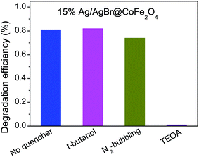 |
| | Fig. 10 Trapping experiments of active species in the BPA photocatalytic degradation over 15% Ag/AgBr@CoFe2O4 composite. | |
To confirm these results, the electron spin resonance (ESR) spectra with dimethyl pyridine N-oxide (DMPO) as the trapping agent were obtained. As shown in Fig. 11, for the 15% Ag/AgBr@CoFe2O4 composite, no obvious characteristic peaks of DMPO-O2˙− and DMPO-˙OH can be observed in the dark. While the light was turned on, characteristic signals of DMPO-O2˙− (Fig. 11A) and DMPOX (Fig. 11B) were observed. The occurrence of DMPOX signals can be ascribed to the immense amount of ˙OH produced by 15% Ag/AgBr@CoFe2O4 composite, which directly oxidized DMPO to DMPOX instead of H2O or OH−.54 The results of the ESR analysis revealed that O2˙− and ˙OH can be formed in the photocatalytic process of Ag/AgBr@CoFe2O4 composites. However, the ESR results are somewhat different than those from the trapping experiments. This is because of the h+, which is generated in the photocatalytic process, and it can directly oxidize the BPA instead of oxidizing the H2O or OH− in the presence of pollutant molecules. Therefore, it can be believed that O2˙− and h+ are the main reactive species in the photocatalytic reactions of Ag/AgBr@CoFe2O4 composites.
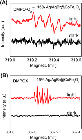 |
| | Fig. 11 ESR spectra of (A) O2˙− and (B) ˙OH in the presence of 15% Ag/AgBr@CoFe2O4 composite. | |
In order to explain the above photocatalytic activity mechanism, the energy band structures of AgBr and CoFe2O4 were determined by DRS analysis (Fig. S3†), XPS-VB (Fig. S9†) and the equation EVB = ECB + Eg, where EVB is the position of the valence band, ECB is the position of the conduction band and Eg is the band gap. The corresponding results are listed in Table 1. According to the band gap structures of Ag/AgBr and CoFe2O4, we first hypothesize a typical Type II structure55 to depict the separation processes of photoexcited electron–hole pairs. As shown in Fig. S10,† in this sense, when Ag/AgBr was coupled with CoFe2O4, on the one hand, the photoexcited electrons from the CB edge of CoFe2O4 will migrate to the CB edges of AgBr because the CB positions of AgBr (−0.06 eV) are lower than that of CoFe2O4 (−0.31 eV). Then, the accumulation of electrons from the CB of AgBr and CoFe2O4 will reduce O2 to generate O2˙−. On the other hand, the accumulation of holes on the VB of AgBr will oxidize H2O to produce ˙OH. This hypothesis is apparently consistent with the results of trapping experiments and ESR analysis. However, on the other hand, since both of the excited electrons are injected into the CB of AgBr, the Ag+ ions in the AgBr are prone to reduction to metallic Ag, which means the stabilities of Ag/AgBr in the Ag/AgBr@CoFe2O4 composites decrease. This is contradictory to the results of the recycling experiments.
Table 1 Energy band structure values of AgBr and CoFe2O4
| |
Eg/eV |
ECB/eV |
EVB/eV |
| AgBr |
2.62 |
−0.06 |
2.56 |
| CoFe2O4 |
0.80 |
−0. 31 |
0.51 |
Accordingly, we have suggested that the present Ag/AgBr@CoFe2O4 composite may have a Z-scheme structure with metallic Ag as an electron mediator system.19,56 To further clarify the role of metallic Ag in the present Z-scheme system, control experiments have been carried out, as shown in Fig. 12. The unsolvothermal treatment of 15% AgBr@CoFe2O4 composite resulted in lower photocatalytic activities than the solvothermal treatment of the composite, wherein 69.5% BPA was degraded. After solvothermal treatment, parts of the Ag+ ions on the surface of AgBr undergo reduction with EG as the reducing agent. The photocatalytic activities of 15% Ag/AgBr@CoFe2O4 composite improve. Based on the above experimental results, we conclude that in the mechanistic pathway (Fig. 13) under light irradiation, both AgBr and CoFe2O4 of the Ag/AgBr@CoFe2O4 composites were photoexcited and they produced electron–hole pairs. Then, the electrons on the CB of AgBr were transferred to metallic Ag and quenched with the holes that come from the VB of CoFe2O4. Meanwhile, the holes left in the VB of AgBr directly oxidize the pollutants (or oxidize H2O to generate ˙OH since the VB position of AgBr is higher than 2.38 eV (˙OH/H2O), which are consistent with the results of the ESR analysis), and the electrons remaining in the CB of CoFe2O4 will be captured by the O2 in the solution to form ˙O2−. Accordingly, the Z-scheme separation process of photoexcited electron–hole pairs is consistently better with the experimental results.18 When compared with other Ag/AgBr-based hybrid materials, the Ag/AgBr@CoFe2O4 composite integrates higher efficiencies for the photocatalytic degradation of organic pollutants, rapid water disinfection and facile magnetic recovery. Therefore, the Ag/AgBr@CoFe2O4 composite shows a great advantage as a new effective visible-light photocatalyst for water purification (Table S2†).
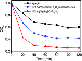 |
| | Fig. 12 A comparison of the photocatalytic activities of pure Ag/AgBr, unsolvothermal treatment of 15% Ag/AgBr@CoFe2O4 composite and 15% Ag/AgBr@CoFe2O4 composites for the degradation of BPA. | |
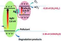 |
| | Fig. 13 Schematic illustration of the photocatalytic process for Ag/AgBr@CoFe2O4 composite under simulated sunlight irradiation. | |
4. Conclusion
In summary, core–shell structured magnetic Ag/AgBr@CoFe2O4 composites have been synthesized. The as-prepared photocatalysts exhibit enhanced photocatalytic performance for the degradation of BPA and 4-CP, which is due to the efficient separation of electron–hole pairs by the introduction of CoFe2O4 NPs. For the Ag/AgBr@CoFe2O4 composites, the 15% Ag/AgBr@CoFe2O4 composite exhibited the best photocatalytic performance. In addition, the composite exhibited improved stabilities for the degradation of colorless pollutants when compared with that of pure Ag/AgBr. The magnetic properties of the Ag/AgBr@CoFe2O4 composites facilitate their separation from water by an external magnetic field after the photocatalytic reaction. Photocatalytic antibacterial experiments reveal that the Ag/AgBr@CoFe2O4 composites possess good antibacterial capability against E. coli under visible light. On the basis of trapping experiments and band structure measurements, a rational Z-scheme pathway photocatalytic mechanism was proposed to depict the separation processes of photoexcited electron–hole pairs.
Acknowledgements
This work is financially supported by the National Natural Science Foundation of China for Youths (No. 21407065, 21506079), Natural Science Foundation of Jiangsu Province for Youths (BK20140533), China Postdoctoral Science Foundation (2014M560399, 2015T80514), Jiangsu Province Postdoctoral Science Foundation (1401143C). A Project Funded by the Priority Academic Program Development of Jiangsu Higher Education.
References
- W. J. Ong, L. L. Tan, Y. H. Ng, S. T. Yong and S. P. Chai, Chem. Rev., 2016, 116, 7159–7329 CrossRef CAS PubMed.
- S. Chu, Y. Cui and N. Liu, Nat. Mater., 2016, 16, 16–22 CrossRef PubMed.
- C. Liu, D. Kong, P. C. Hsu, H. Yuan, H. W. Lee, Y. Liu, H. Wang, S. Wang, K. Yan, D. Lin, P. A. Maraccini, K. M. Parker, A. B. Boehm and Y. Cui, Nat. Nanotechnol., 2016, 11, 1098–1104 CAS.
- D. Wang and D. Astruc, Chem. Rev., 2014, 114, 6949–6985 CrossRef CAS PubMed.
- P. Wang, B. Huang, X. Qin, X. Zhang, Y. Dai, J. Wei and M. H. Whangbo, Angew. Chem., Int. Ed., 2008, 47, 7931–7933 CrossRef CAS PubMed.
- Y. Zhao, C. Lin, H. Bi, Y. Liu and Q. Yan, Appl. Surf. Sci., 2017, 392, 701–707 CrossRef CAS.
- S. Ning, H. Lin, Y. Tong, X. Zhang, Q. Lin, Y. Zhang, J. Long and X. Wang, Appl. Catal., B, 2017, 204, 1–10 CrossRef CAS.
- Z. Yi, J. Ye, N. Kikugawa, T. Kako, S. Ouyang, H. Stuart-Williams, H. Yang, J. Cao, W. Luo, Z. Li, Y. Liu and R. L. Withers, Nat. Mater., 2010, 9, 559–564 CrossRef CAS PubMed.
- L. Jing, Y. Xu, S. Huang, M. Xie, M. He, H. Xu, H. Li and Q. Zhang, Appl. Catal., B, 2016, 199, 11–22 CrossRef CAS.
- H. Dong, G. Chen, J. Sun, C. Li, Y. Yu and D. Chen, Appl. Catal., B, 2013, 134–135, 46–54 CrossRef CAS.
- J. Lv, K. Dai, J. Zhang, L. Lu, C. Liang, L. Geng, Z. Wang, G. Yuan and G. Zhu, Appl. Surf. Sci., 2017, 391, 507–515 CrossRef CAS.
- Y. Xu, H. Xu, J. Yan, H. Li, L. Huang, Q. Zhang, C. Huang and H. Wan, Phys. Chem. Chem. Phys., 2013, 15, 5821–5830 RSC.
- T. Yan, H. Zhang, Q. Luo, Y. Ma, H. Lin and J. You, Chem. Eng. J., 2013, 232, 564–572 CrossRef CAS.
- H. Xu, J. Yan, Y. Xu, Y. Song, H. Li, J. Xia, C. Huang and H. Wan, Appl. Catal., B, 2013, 129, 182–193 CrossRef CAS.
- H. Zhao, L. Zhang, X. Gu, S. Li, B. Li, H. Wang, J. Yang and J. Liu, RSC Adv., 2015, 5, 10951–10959 RSC.
- Y. Fan, W. Ma, D. Han, S. Gan, X. Dong and L. Niu, Adv. Mater., 2015, 27, 3767–3773 CrossRef CAS PubMed.
- R. Chalasani and S. Vasudevan, ACS Nano, 2013, 7, 4093–4104 CrossRef CAS PubMed.
- D. J. Martin, G. Liu, S. J. Moniz, Y. Bi, A. M. Beale, J. Ye and J. Tang, Chem. Soc. Rev., 2015, 44, 7808–7828 RSC.
- X. Wu, J. Zhao, L. Wang, M. Han, M. Zhang, H. Wang, H. Huang, Y. Liu and Z. Kang, Appl. Catal., B, 2017, 206, 501–509 CrossRef CAS.
- L. Ye, J. Liu, C. Gong, L. Tian, T. Peng and L. Zan, ACS Catal., 2012, 2, 1677–1683 CrossRef CAS.
- R. Xie, L. Zhang, H. Xu, Y. Zhong, X. Sui and Z. Mao, J. Mol. Catal. A: Chem., 2015, 406, 194–203 CrossRef CAS.
- B. Zhu, P. Xia, Y. Li, W. Ho and J. Yu, Appl. Surf. Sci., 2017, 391, 175–183 CrossRef CAS.
- J. He, D. W. Shao, L. C. Zheng, L. J. Zheng, D. Q. Feng, J. P. Xu, X. H. Zhang, W. C. Wang, W. H. Wang, F. Lu, H. Dong, Y. H. Cheng, H. Liu and R. K. Zheng, Appl. Catal., B, 2017, 203, 917–926 CrossRef CAS.
- S. Huang, Y. Xu, Z. Chen, M. Xie, H. Xu, M. He, H. Li and Q. Zhang, RSC Adv., 2015, 5, 71035–71045 RSC.
- B. Tian, T. Wang, R. Dong, S. Bao, F. Yang and J. Zhang, Appl. Catal., B, 2014, 147, 22–28 CrossRef CAS.
- P. Xiong, H. Huang and X. Wang, J. Power Sources, 2014, 245, 937–946 CrossRef CAS.
- H. Zhu, S. Zhang, Y. X. Huang, L. Wu and S. Sun, Nano Lett., 2013, 13, 2947–2951 CrossRef CAS PubMed.
- L. Lu, Q. Hao, W. Lei, X. Xia, P. Liu, D. Sun, X. Wang and X. Yang, Small, 2015, 11, 5833–5843 CrossRef CAS PubMed.
- Y. Xu, W. Bian, J. Wu, J.-H. Tian and R. Yang, Electrochim. Acta, 2015, 151, 276–283 CrossRef CAS.
- S. Li, B. Wang, J. Liu and M. Yu, Electrochim. Acta, 2014, 129, 33–39 CrossRef CAS.
- Y. Fu, H. Chen, X. Sun and X. Wang, Appl. Catal., B, 2012, 111–112, 280–287 CrossRef CAS.
- D. Zhang, X. Pu, Y. Gao, C. Su, H. Li, H. Li and W. Hang, Mater. Lett., 2013, 113, 179–181 CrossRef CAS.
- N. Zhang, Y. Huang, M. Zong, X. Ding, S. Li and M. Wang, Chem. Eng. J., 2017, 308, 214–221 CrossRef CAS.
- Z. Yang, Y. Shi and B. Wang, Appl. Surf. Sci., 2017, 399, 192–199 CrossRef CAS.
- L. Gan, L. Xu and K. Qian, Mater. Des., 2016, 109, 354–360 CrossRef CAS.
- P. Xiong, L. Wang, X. Sun, B. Xu and X. Wang, Ind. Eng. Chem. Res., 2013, 52, 10105–10113 CrossRef CAS.
- Q. Wang, T. Hisatomi, Q. Jia, H. Tokudome, M. Zhong, C. Wang, Z. Pan, T. Takata, M. Nakabayashi, N. Shibata, Y. Li, I. D. Sharp, A. Kudo, T. Yamada and K. Domen, Nat. Mater., 2016, 15, 611–615 CrossRef CAS PubMed.
- Y. Xu, T. Zhou, S. Huang, M. Xie, H. Li, H. Xu, J. Xia and H. Li, RSC Adv., 2015, 5, 41475–41483 RSC.
- A. López-Ortega, E. Lottini, C. d. J. Fernández and C. Sangregorio, Chem. Mater., 2015, 27, 4048–4056 CrossRef.
- M. S. Sher Shah, W. J. Kim, J. Park, K. Rhee do, I. H. Jang, N. G. Park, J. Y. Lee and P. J. Yoo, ACS Appl. Mater. Interfaces, 2014, 6, 20819–20827 CAS.
- Y. Zhao, B. Zhao, J. Liu, G. Chen, R. Gao, S. Yao, M. Li, Q. Zhang, L. Gu, J. Xie, X. Wen, Li-Z. Wu, C.-H. Tung, D. Ma and T. Zhang, Angew. Chem., Int. Ed., 2016, 55, 4215–4219 CrossRef CAS PubMed.
- G. Muscas, G. Singh, W. R. Glomm, R. Mathieu, P. A. Kumar, G. Concas, E. Agostinelli and D. Peddis, Chem. Mater., 2015, 27, 1982–1990 CrossRef CAS.
- J. Yi, X. She, Y. Song, H. Xu, P. Zhang, Z. Mo, L. Liu, D. Du and H. Li, RSC Adv., 2016, 6, 112420–112428 RSC.
- Y. Li, S. Ouyang, H. Xu, X. Wang, Y. Bi, Y. Zhang and J. Ye, J. Am. Chem. Soc., 2016, 138, 13289–13297 CrossRef CAS PubMed.
- N. Barbero and D. Vione, Environ. Sci. Technol., 2016, 50, 2130–2131 CrossRef CAS PubMed.
- J. Xia, J. Di, H. Li, H. Xu, H. Li and S. Guo, Appl. Catal., B, 2016, 181, 260–269 CrossRef CAS.
- J. Di, J. Xia, Y. Ge, H. Li, H. Ji, H. Xu, Q. Zhang, H. Li and M. Li, Appl. Catal., B, 2015, 168–169, 51–61 CrossRef CAS.
- J. Di, J. Xia, M. Ji, B. Wang, S. Yin, Q. Zhang, Z. Chen and H. Li, ACS Appl. Mater. Interfaces, 2015, 7, 20111–20123 CAS.
- M. Zhu, P. Chen and M. Liu, ACS Nano, 2011, 5, 4259–4536 Search PubMed.
- H. Sun, G. Li, X. Nie, H. Shi, P. K. Wong, H. Zhao and T. An, Environ. Sci. Technol., 2014, 48, 9412–9419 CrossRef CAS PubMed.
- Y. Jia, S. Zhan, S. Ma and Q. Zhou, ACS Appl. Mater. Interfaces, 2016, 8, 6841–6851 CAS.
- T. W. Ng, L. Zhang, J. Liu, G. Huang, W. Wang and P. K. Wong, Water Res., 2016, 90, 111–118 CrossRef CAS PubMed.
- D. Xia, T. An, G. Li, W. Wang, H. Zhao and P. K. Wong, Water Res., 2016, 99, 149–161 CrossRef CAS PubMed.
- Y. Wang, H. Sun, H. M. Ang, M. O. Tade and S. Wang, ACS Appl. Mater. Interfaces, 2014, 6, 19914–19923 CAS.
- S. Bai, J. Jiang, Q. Zhang and Y. Xiong, Chem. Soc. Rev., 2015, 44, 2893–2939 RSC.
- H. Shen, J. Wang, J. Jiang, B. Luo, B. Mao and W. Shi, Chem. Eng. J., 2017, 313, 508–517 CrossRef CAS.
Footnote |
| † Electronic supplementary information (ESI) available. See DOI: 10.1039/c7ra03936k |
|
| This journal is © The Royal Society of Chemistry 2017 |
Click here to see how this site uses Cookies. View our privacy policy here.  Open Access Article
 *a,
Meng Xiea,
Qingqing Liua,
Hui Xub,
Yan Zhaob,
Minqiang Hea and
Huaming Li*b


