 Open Access Article
Creative Commons Attribution 3.0 Unported Licence
Transparent superhydrophobic PTFE films via one-step aerosol assisted chemical vapor deposition†
Aoyun
Zhuang
 ab,
Ruijin
Liao
*a,
Sebastian C.
Dixon
 b,
Yao
Lu
 b,
Sanjayan
Sathasivam
b,
Ivan P.
Parkin
b,
Sanjayan
Sathasivam
b,
Ivan P.
Parkin
 b and
Claire J.
Carmalt
 *b
*b
aState Key Laboratory of Power Transmission Equipment & System Security and New Technology, Chongqing University, Chongqing 400044, China. E-mail: rjliao@cqu.edu.cn
bDepartment of Chemistry, University College London, London, WC1H 0AJ, UK. E-mail: c.j.carmalt@ucl.ac.uk; Tel: +44 (0)20 7679 4637
First published on 5th June 2017
Abstract
In this study, hierarchical micro/nano-structured transparent superhydrophobic polytetrafluoroethylene (PTFE) films showing a water contact angle (CA) of 168°, a water sliding angle (SA) <1° and transmittance to visible light >90% were prepared on glass substrates via aerosol-assisted chemical vapor deposition (AACVD). Scanning electron microscopy showed the morphology to be rough, composed of both micro and nano sized protrusions. Mechanical testing showed that after impingement from 800 drops of 15 μL water (height = 1 m) or 10 g of sand grains (height = 65 cm), the CA of the transparent PTFE surface was still >150°, still demonstrating excellent superhydrophobicity. The films also showed self-cleaning and anti-corrosion properties. This one-step fabrication is a facile way of producing various kinds of transparent superhydrophobic surfaces.
1. Introduction
Inspired by surfaces found in nature, such as the leaves of the Lotus plant and the skin of water walking arthropods that show an apparent water contact angle (CA) larger than 150° and low contact angle hysteresis,1–3 superhydrophobic surfaces have attracted considerable scientific attention in a range of fields such as self-cleaning and anti-corrosion.4,5 Self-cleaning involves two aspects – stain-resistance and dirt-removal; water rolls and even bounces off a superhydrophobic surface so that the surface does not get stained; the dirt is also removed by the rolling motion of the water droplets.6 As the surface is water-proofed, it is difficult to be corroded even when it is exposed to corrosive liquids such as strong acid and base.7,8 The anti-corrosion property is of great importance to extend the life of the coating, especially for the application of the films in the outdoor environment. There are two types of superhydrophobic surfaces – one described by the Wenzel model whereby the water droplet forms an intimate contact with the surface, and another described by the Cassie–Baxter model where the droplet rests on the solid/gas composite formed from air that is trapped by grooves between surface features. For both models, the morphology of the surface needs to be sufficiently rough (with roughness generally in the nano/micro regime) and surface energy sufficiently low. As such, synthetic routes to superhydrophobic surfaces are generally obtained via a two-step process.9,10 A variety of methods, such as plasma etching, sol–gel synthesis, electrical deposition and electrospinning, have been reported for the fabrication of superhydrophobic surfaces.11–14 In previous literature, surfaces with excellent superhydrophobic properties have been prepared, including those with mechanical robustness and superamphiphobicity.15–17 Lu et al. were able to synthesize robust self-cleaning surfaces on various substrates with an ethanolic suspension of perfluorosilane-coated titanium dioxide nanoparticles.18 Ellinas and co-workers fabricated hierarchical textured cyclo-olefin-polymer surfaces with micro- and nano-scopic features for biomolecule immobilization with environmentally stable superhydrophobic and superoleophobic behavior.19 In addition, much attention has been given to creating superhydrophobic surfaces with two or more functional properties, such as photocatalytic, antimicrobial or superamphiphobic behavior.20–22 However, most of these methods involve either complex fabrication process (two or more steps), or expensive chemicals, which makes it difficult for large-scale production and application.There is great interest in visible light transparent superhydrophobic surfaces due to their applications in architectural glazing, screens for electronic devices and protective layers for solar panels.23 However, to obtain coatings that are both transparent and sufficiently rough enough to display superhydrophobicity is challenging due to the competing nature of both properties, i.e. as roughness increases, superhydrophobicity increases but transparency decreases due to increased light scattering.24 Over the last few years, there has been a proliferation of studies on methods and technologies for producing transparent superhydrophobic surfaces.25,26 However, most of these approaches are limited in practical applications due to their complexities and high cost, as a result of strict processing conditions or sophisticated equipment.
In an effort to achieve mass production of transparent superhydrophobic surfaces, some facile methods have been reported.27–29 Modified nanoparticles have been widely used to prepare transparent coatings as they can provide the rough structure and low surface energy. However, only a small range of nanoparticulate materials can be used in transparent films as most induce strong reflection of visible light. Polytetrafluoroethylene (PTFE) nanoparticles have proved to be better than most in allowing the transmission of visible light. PTFE is also well known for its low surface energy (∼18 mN m−1),30 crucial for a hydrophobic interaction with water, due to many superhydrophobic –CF3 groups. M. Drábik et al. have successfully used RF magnetron sputtering to prepare PTFE coatings with excellent superhydrophobicity with water CA as high as 170°.31 However, the films were not transparent and the operation of RF magnetron sputtering was comparably complex.
Aerosol-assisted chemical vapor deposition (AACVD) is a simple and easily scalable technique that operates at ambient pressure.32,33 Precursors for AACVD are dissolved in a suitable solvent and delivered to the CVD chamber in the form of aerosol droplets. As such, the precursors need not be volatile, only soluble in a suitable solvent. This allows a wide range of precursors that are usually unsuitable for traditional CVD techniques to be used. AACVD has been used to fabricate a wide range of materials (TiO2, GaAs, BiOX (where X = Cl, Br, I), SnO2: F) for a wide range of applications (e.g. photocatalysis, photovoltaics and transparent conducting oxides).34–36 AACVD has also been previously employed to make non-transparent polymeric superhydrophobic coatings.37,38 This paper describes the novel single step synthesis of highly transparent (over 90% transmittance of visible light) and superhydrophobic PTFE coatings using AACVD.
2. Experimental
2.1 Materials
Polytetrafluoroethylene precursor solution (60 wt% aqueous dispersion) was purchased from Aldrich Chemical Inc. Alpha-[3,5-dimethyl-1-(2-methylpropyl)hexyl]-omega-poly(oxy-2-ethanediyl) (Tergitol TMN-6) was contained in the PTFE precursor as the emulsifier, here, the surface energy of the precursor coated flat surface was 14.8 mN m−1, which was determined by Owens–Wendt method39 as shown in ESI.† Deionized water (15.6 MΩ cm) was used as the dispersion medium. Silica barrier coated glass substrates were obtained from Pilkington NSG. Standard microscope glass slides and the sand grains used to test the wear resistance were purchased from VWR International, Inc.2.2 Fabrication of superhydrophobic films
As shown in Fig. 1, a cold-walled AACVD technique was used to fabricate the transparent superhydrophobic films. The AACVD process utilizes polytetrafluoroethylene preparation (typically 1 mL) in solution with 3 mL deionized water. The depositions were carried out in a cold-walled horizontal-bed CVD reactor. The reactor contained a bottom plate (dimensions: 145 mm × 45 mm × 4 mm) and a top carbon block from which the CVD reactor was heated. Four microscope glass slides were placed on the surface of the bottom plate which was positioned 8 mm below and parallel to the carbon block. The complete assembly was enclosed within a quartz tube. A PIFCO ultrasonic humidifier (power = 25 W, frequency = 40 kHz) was used to form a precursor aerosol which was transported using nitrogen gas (1.0 L min−1). Depositions typically took 15 min at a reactor temperature of 450 °C. The highly transparent PTFE-coated substrates were cooled under nitrogen and handled in air after the deposition.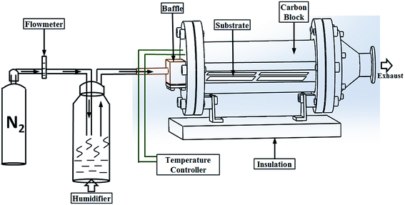 | ||
| Fig. 1 The illustration of one-step AACVD to form superhydrophobic PTFE surfaces with high transparency. | ||
Tergitol TMN-6 + PTFE precursor was spin-coated onto a glass slide followed by 450 °C annealing for ∼30 s to get the flat PTFE film.
2.3 Characterization
The surface morphologies of the samples were observed using a JEOL JSM-6301F scanning electron microscope. The samples were vacuum sputtered with a very thin film of gold to improve surface electrical conductivity. UV-vis absorption spectra were recorded using a Perkin Elmer Lambda 950 UV/VIS spectrometer single beam instrument over a range of 200–800 nm. ATR-FTIR measurements were taken over a range of 700–4000 cm−1 using a Perkin-Elmer Spectrum-100 (Ge crystal) equipped with a universal ATR attachment. X-ray photoelectron spectroscopy (XPS) was conducted on a Thermo Scientific K-alpha spectrometer with monochromated Al Kα radiation, a dual beam charge compensation system and constant pass energy of 50 eV (spot size 400 μm). XPS data was fitted using XPSPeak software. Water contact angle measurements were carried out using an FTA-1000 drop shape instrument; 5 μL water droplets were used and the CA of the water droplet was directly observed. Sliding angle measurements were performed using the tilted drop method, with a water droplet size of 15 μL. A high-speed camera (Phantom v411, Vision Research, Inc.) was used to record the bounce dynamics of water droplets on the transparent superhydrophobic PTFE surfaces.3. Results and discussion
3.1 Composition of films
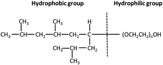
Thin films of PTFE were deposited via AACVD on microscope slides from a polytetrafluoroethylene preparation solution (1 mL PTFE in 3 mL of deionized water) at 450 °C. The films covered 100% of the substrate and were well adhered to the glass. Fig. 2(a) shows high-resolution X-ray photoelectron spectroscopy (XPS) data for the PTFE film for the C 1s region. The raw data was deconvoluted to four components with equal peak width corresponding to –CF2 at 292.1 eV, C–O at 288.0 eV,![[C with combining low line]](https://www.rsc.org/images/entities/char_0043_0332.gif) –CF at 286.2 eV and C–C/C–H at 284.6 eV.40,41 The major peak with an area corresponding to a relative concentration of 63.6% corresponded to the –CF2 functional group of the PTFE film. These –CF2 groups confer a low surface energy to the films, so are therefore crucial to their superhydrophobicity. In addition, the C–H and C–O peaks, also shown in Fig. 2(a), are due to the alpha-[3,5-dimethyl-1-(2-methylpropyl)hexyl]-omega-poly(oxy-2-ethanediyl) (Tergitol TMN-6) contained in the PTFE precursor. It can be found that TMN is composed of a hydrophobic group and hydrophilic group, as seen from its structure shown in Fig. 3. It is believed that during the deposition, the TMN component of the solution reacts with the substrate in a process whereby the hydrophilic groups of TMN bind to Si–OH at the glass surface by condensation of H2O. This change is important for reducing the surface energy of the substrate by converting the substrate from hydrophilic to hydrophobic, on account of the outward-facing hydrophobic tail of the TMN molecule.
–CF at 286.2 eV and C–C/C–H at 284.6 eV.40,41 The major peak with an area corresponding to a relative concentration of 63.6% corresponded to the –CF2 functional group of the PTFE film. These –CF2 groups confer a low surface energy to the films, so are therefore crucial to their superhydrophobicity. In addition, the C–H and C–O peaks, also shown in Fig. 2(a), are due to the alpha-[3,5-dimethyl-1-(2-methylpropyl)hexyl]-omega-poly(oxy-2-ethanediyl) (Tergitol TMN-6) contained in the PTFE precursor. It can be found that TMN is composed of a hydrophobic group and hydrophilic group, as seen from its structure shown in Fig. 3. It is believed that during the deposition, the TMN component of the solution reacts with the substrate in a process whereby the hydrophilic groups of TMN bind to Si–OH at the glass surface by condensation of H2O. This change is important for reducing the surface energy of the substrate by converting the substrate from hydrophilic to hydrophobic, on account of the outward-facing hydrophobic tail of the TMN molecule.
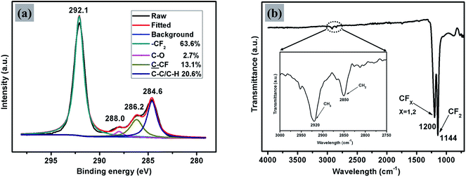 | ||
| Fig. 2 Peak-fitted high-resolution (a) C 1s XPS spectrum and (b) FTIR spectrum for the AACVD prepared transparent superhydrophobic PTFE film. | ||
The XPS results were supported by FTIR spectroscopy, as shown in Fig. 2(b). The main absorption band of the spectrum situated between 1050 cm−1 and 1350 cm−1 is composed of two peaks at 1144 cm−1 and 1200 cm−1 with a shoulder at about 1173 cm−1. These were assigned to symmetric and asymmetric stretching vibrations of CF2 bond and stretching vibration of CF bond in CF3–(CF2)n, respectively.32 As can be seen from the spectrum between 2750 cm−1 and 3000 cm−1, there were two small peaks at 2850 cm−1 and 2920 cm−1 with a shoulder at about 2879 cm−1. These were assigned to symmetric and asymmetric stretching vibrations of CH2 bonds, which are again likely to be due to the TMN contained in the PTFE preparation. No absorption peak corresponding to the Si–OH stretching vibration has been observed in the region 3000–3500 cm−1 which further suggests that the TMN had reacted by condensation with the substrate in the manner described above.
3.2 Surface morphology
Scanning electron micrographs (SEM) of the films, as depicted in Fig. 4, illustrate the rough morphology of the superhydrophobic PTFE film and the size distribution of the particles. Fig. 4(a) showed that nano-sized PTFE particles were arranged in microscopic clusters distributed across the surface, with each cluster separated by about 1 μm; the particle size was concentrated in the 300 nm–2 μm range. The CA of the film was up to 168°, as shown in the upper right corner of Fig. 4(a). As calculated by ImageJ software, the area uncovered by the particles was about 70% of the substrate, facilitating penetration of the films by visible light, thereby improving the transparency compared with denser structures.35Fig. 4(b) shows the microscopic particle clusters up-close, with PTFE particles in a stacked arrangement with the base of these structures playing the role of bonding the clusters to the substrate. Meanwhile, the smaller nano-scale particles apparent as protrusions on the surface of the micro-structure, with diameters between 200 and 300 nm, would be expected to greatly contribute to superhydrophobicity. Such hierarchical micro-/nano-scaled structures can create gaps in which air can become trapped, while, as has been analyzed above, the bare hydrophilic glass substrate has been modified to a hydrophobic substrate by TMN, which also leads to a larger CA. At higher magnification, as shown in Fig. 4(c), it is clearly seen that some nano-scale PTFE particles were also directly bound to the substrate, distributed around the micro-clusters, which may further reduce the contact between water droplets and the bare substrate.3.3 Transparency of the film
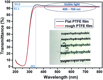
In Fig. 5 is a photograph showing water droplets on the superhydrophobic PTFE film surface, alongside a plot of its optical transmittance around the visible region. It can be seen that in the visible region and near-UV, the films have a uniformly high transmittance of over 92%, just a little lower than that of the flat PTFE film (94%), while the photograph illustrates that this translates to a high degree of visible transparency and clarity. Below 340 nm there was a sharp drop in transmittance arising from absorption by the glass substrate. The excellent optical transmittance of the film was due to a combination of the intrinsic high transparency of PTFE itself, and the spatial separation of PTFE micro and nano particles, facilitating the light transmission. Such high optical transparency is desirable for many practical water-repelling self-cleaning surface applications.To understand the factors that influence the transparency of the thin films, we compared our PTFE film with a spin-coated PTFE surface at a similar coating thickness. Fig. 6(a) shows a spin-coated surface with the Tergitol TMN-6 + PTFE precursor (sample A). Fig. 6(b) shows the surface that was fabricated to be porous film by one-step AACVD method introduced in the manuscript (sample B). Fig. 6(c) and (d) shows the SEM images of the samples that were shown in Fig. 6(a) and (b), respectively. Although the coating on sample A has a similar thickness as that of sample B, the coating on sample A had better transparency than that of sample B. It indicates that the coating transparency does not fully depend on their thickness.
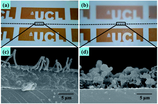 | ||
| Fig. 6 Optical photograph of (a) spin-coated and (b) AACVD coated PTFE films (above the dotted line) on the A4 paper. (c) and (d) Cross-sectional SEM images of respective thin films. | ||
Fig. 7 shows the SEM, optical and water contact angle measurement images of three samples with different densities of surface structures. The sample as shown in Fig. 7(a) has the least textured morphology, which gives it the best transparency; however, the water contact angle of this sample was only 139.6°, which is not considered to be superhydrophobic. The sample as shown in Fig. 7(b) had more condensed textures than those in Fig. 7(a), so that the water contact angle of this sample dramatically increased to be 168.3°, showing its superhydrophobicity; and the transparency of the sample shown in Fig. 7(b) is 92%, which is acceptable. Given more surface roughness, the sample as shown in Fig. 7(c) had a water contact angle of 169.6°, which is slightly higher than that of the sample shown in Fig. 7(b). However, the transparency dramatically decreased. Therefore, the superhydrophobicity and thin film transparency are dependent on how condensed of surface textures. Less surface morphology would achieve better transparency, but with a lower water contact angle; when a higher water contact angle is achieved, the surface is more textured, but the transparency decreased. To balance the transparency and superhydrophobicity, the sample as shown in Fig. 7(b) is preferred.
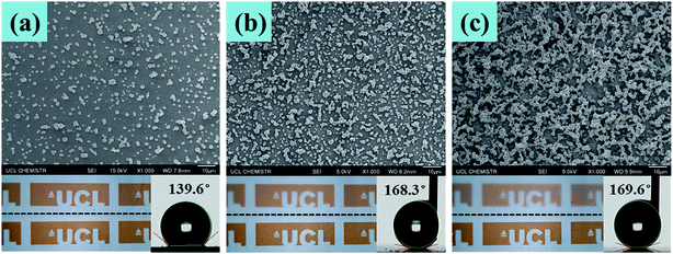 | ||
| Fig. 7 SEM, optical and water contact angle measurement images of three samples with different densities of surface structures. | ||
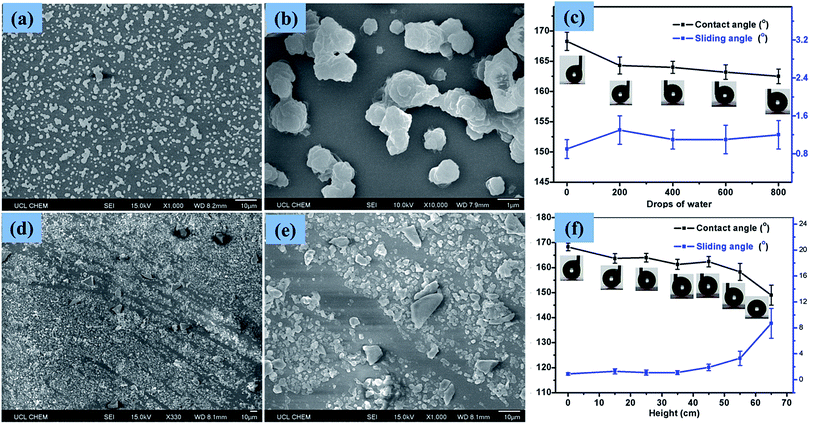
3.4 Wear resistance of surface
In order to test the stability of the coating upon the impact of water droplets, water droplets (∼15 μL) were dropped from a 1 m height onto a horizontally positioned superhydrophobic PTFE sample. Fig. 8(a) and (b) showed the surface structure of the PTFE film after 800 such droplets impacted. It is apparent that most of the micro and nano PTFE particles were still closely bound to the substrate, suggesting that the films were resilient to wear. The CA of droplets on the film was somewhat reduced and the SA was slightly increased, though with superhydrophobicity retained throughout the testing. Fig. 8(c) illustrates the effect on the CA and SA of increased wear, with CA and SA measurements taken every 200 droplet impacts up to 800 impacts, at which point the CA was still above 160° and the SA remained below 2°. The strong adhesion of the PTFE clusters to the glass substrate caused that the particles were tightly connected to the substrate without being washed away by water droplets. The low surface energy of the PTFE itself is another important aspect which had a strong repellent effect on the water droplets. The stable wettability of the transparent superhydrophobic PTFE coating upon the impact of water droplets is meaningful for the self-cleaning windows in the outdoor environment.To test the wear resistance of the film in more harsh conditions, 10 g of sand grains was dropped from different heights (15 cm–65 cm) onto a slightly tilted surface shown in the online ESI Movie S1.† After the impact of the sand grains, the water droplet CA and SA were measured to investigate the impact on the films' superhydrophobicity. Fig. 8(d) and (e) showed the surface structure of the superhydrophobic PTFE film after the sand impingement from 65 cm height. As can be seen from Fig. 8(d), the micro and nano sized PTFE protrusions were washed away by the sand grains, forming some scratches, thereby reducing the superhydrophobicity of PTFE film. According to the result shown in Fig. 8(f), the superhydrophobicity of the film exhibited a downward trend with increasing dropping height. The CA of the film reduced to 149° while the SA increased to 9° after sand impingement from 65 cm height, though the film still retained superhydrophobicity. This observation is apparently due to the fact that most of the PTFE protrusions were able to resist sand grains impingement at a certain height (<45 cm). This property is of great importance for the long-term use of this transparent superhydrophobic film.
3.5 Water drop bounce dynamics
A high-speed camera was used to capture the bounce dynamics of water droplets on superhydrophobic PTFE surfaces under ambient conditions at a rate of 3000 fps. As shown in the optical images below (Fig. 9(a)), a water drop was released from a height of 9.8 mm onto the superhydrophobic PTFE surface. At t = 42 ms, the water drop started to impact the superhydrophobic surface at a speed of 0.41 m s−1, and then it detached from the surface (t = 54 ms), moving upwards until its velocity reduced to 0 m s−1 where the height of the water drop was 4.2 mm (t = 78 ms). From the height of the water drop at different times shown in Fig. 9(b), it can be found that there were more than eight such reciprocating motions due to the little adhesion between the film and the water drops, which exhibited the excellent superhydrophobicity of the transparent PTFE film. The whole bounce dynamics of water droplets on superhydrophobic PTFE surfaces can be seen in the online ESI Movie S2.†3.6 Anti-corrosion of surface
Coatings applied to the outdoor environment are sometimes suffered from the acid rain, requiring that they possess proper anti-corrosion property, which is an important aspect in relation to the life of coatings. To investigate the acid-alkali resistance of the superhydrophobic PTFE surface, experiments were performed by soaking superhydrophobic surface in hydrochloric acid solution and sodium hydroxide solution over a wide pH range from 1 to 14 for 24 h. The CAs and SAs of resulting surfaces after soaking are shown in Fig. 10. The wettability of the PTFE film was slightly affected by hydrochloric acid (pH = 1–6) and the low concentrated sodium hydroxide solution (pH = 8–12). The CA of the surface was still >155° and SA was <4° even after soaking in hydrochloric acid at pH = 1 for 24 hours. However, the corrosion of the sodium hydroxide to the film appeared more severe than that of hydrochloric acid, especially for pH ≥ 13 sodium hydroxide. The wettability of the film changed a lot after soaking in the strong sodium hydroxide (pH ≥ 13) which may be due to a particular vulnerability of the TMN-to-glass binding to strong basic conditions, thereby resulting in a partial separation of the film from the substrate and reducing the superhydrophobicity of the PTFE surface.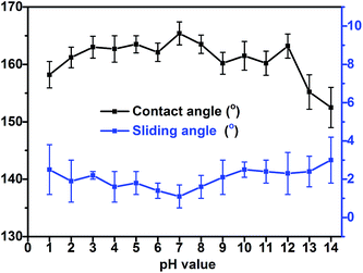 | ||
| Fig. 10 Contact angles and sliding angles of the sample film after soaking in hydrochloric acid solution and sodium hydroxide solution over a wide pH range from 1 to 14 for 24 h. | ||
3.7 Self-cleaning of surface
Aqueous methylene blue dye and activated carbon powder were used to investigate the self-cleaning property of the superhydrophobic PTFE surface depicted in Fig. 11, Movie S3 and S4 (see ESI†). As shown in Fig. 11(a)–(e), the untreated glass surface was easily wetted by the aqueous dye while the superhydrophobic PTFE surface remained dry and stain-free. As a representative example of contaminant, activated carbon powder was dispersed on both the tilted superhydrophobic surface and the untreated glass surface, and water droplets were then continuously dropped onto the two surfaces shown in Fig. 11(f)–(j). It was clearly observed that water drops effectively picked up carbon powder and rolled away from the superhydrophobic PTFE surface, thus achieving the self-cleaning performance. In contrast, some carbon powder was still left on the untreated glass surface. This so-called ‘Lotus effect’ shows great potential for dirt-resistant self-cleaning applications from automotive and architectural glazing to solar cells.In order to investigate that how many cycles the transparent superhydrophobic PTFE surfaces could be self-cleaned and the PH effect on the self-cleaning, aqueous dye was dropped onto the sample films firstly, and then hydrochloric acid solution (pH = 1) and sodium hydroxide solution (pH = 14) were dropped to pick up carbon powder on the superhydrophobic PTFE surface respectively. 10 such cycles were repeated, and the tenth result was shown in the following Fig. 12(a)–(c), which showed that the film still exhibited stable self-cleaning property after 10 times tests. Congo red, Trypan blue, Cresol red and Titan yellow liquid were used to test the self-cleaning property for different liquids, and the results were shown in the Fig. 12(d)–(g) which exhibited that the superhydrophobic PTFE surface remained dry and stain-free after dropping these four different liquids.
4. Conclusion
Transparent superhydrophobic films with hierarchical micro/nano-structured PTFE were prepared on glass substrates using a one-step aerosol-assisted chemical vapor deposition. The films demonstrated water droplet contact angles up to 168°, sliding angles less than 1° and excellent optical transmittance exceeding 92% in the visible range (400–760 nm). Rigorous wear testing demonstrated that, after the impingement of water droplets or sand grains, the coating still retained superhydrophobic performance. Meanwhile, the film also demonstrated excellent performance in self-cleaning and anti-corrosion. This simple and low-cost method for PTFE deposition is not only suitable for the fast and large-scale preparation of transparent superhydrophobic PTFE surfaces, but also provides a new potential route for the preparation of other transparent superhydrophobic polymer films.Acknowledgements
This work is financially supported by the General Program of Natural Science Foundation of China (51377177). The authors would also like to acknowledge and thank NSG Pilkington Glass Ltd. and the EPSRC for studentship funding (S. C. D.) through the M3S Doctoral Training Centre (grant EP/G036675). The UCL Chemistry departmental workshop is thanked for their contribution to the schematic in Fig. 1.References
- W. Barthlott and C. Neinhuis, Planta, 1997, 202, 1–8 CrossRef CAS.
- M. Denny, Science, 2008, 7013 Search PubMed.
- W. Lee, M. K. Jin, W. C. Yoo and J. K. Lee, Langmuir, 2004, 20, 7665–7669 CrossRef CAS PubMed.
- Z. Zhang, B. Ge, X. Men and Y. Li, Colloids Surf., A, 2016, 490, 182–188 CrossRef CAS.
- N. Wang, D. Xiong, Y. Deng, Y. Shi and K. Wang, ACS Appl. Mater. Interfaces, 2015, 7, 6260–6272 CAS.
- I. P. Parkin and R. G. Palgrave, J. Mater. Chem., 2005, 15, 1689–1695 RSC.
- Y. Lu, S. Sathasivam, J. Song, F. Chen, W. Xu, C. J. Carmalt and I. P. Parkin, J. Mater. Chem. A, 2014, 2, 11628 CAS.
- W. Xu, J. Song, J. Sun, Y. Lu and Z. Yu, ACS Appl. Mater. Interfaces, 2011, 3, 4404–4414 CAS.
- Y. Li, S. Li, Y. Zhang, M. Yu and J. Liu, Mater. Lett., 2015, 142, 137–140 CrossRef CAS.
- S. Choo, H. J. Choi and H. Lee, Mater. Lett., 2014, 121, 170–173 CrossRef CAS.
- H. C. Barshilia and N. Gupta, Vacuum, 2014, 99, 42–48 CrossRef CAS.
- S. S. Latthe, C. Terashima, K. Nakata, M. Sakai and A. Fujishima, J. Mater. Chem. A, 2014, 2, 5548 CAS.
- Y. Liu, X. Yin, J. Zhang, S. Yu, Z. Han and L. Ren, Electrochim. Acta, 2014, 125, 395–403 CrossRef CAS.
- Z. Liu, H. Wang, E. Wang, X. Zhang, R. Yuan and Y. Zhu, Polymer, 2016, 82, 105–113 CrossRef CAS.
- X. Gao, J. Zhou, R. Du, Z. Xie, S. Deng, R. Liu, Z. Liu and J. Zhang, Adv. Mater., 2016, 28, 168–173 CrossRef CAS PubMed.
- P. Wang, M. Chen, H. Han, X. Fan, Q. Liu and J. Wang, J. Mater. Chem. A, 2016, 4, 7869–7874 CAS.
- F. Chen, J. Song, Y. Lu, S. Huang, X. Liu, J. Sun, C. J. Carmalt, I. P. Parkin and W. Xu, J. Mater. Chem. A, 2015, 3, 20999–21008 CAS.
- Y. Lu, S. Sathasivam, J. Song, C. R. Crick, C. J. Carmalt and I. P. Parkin, Science, 2015, 347, 1132–1135 CrossRef CAS PubMed.
- K. Ellinas, K. Tsougeni, P. S. Petrou, G. Boulousis, D. Tsoukleris, E. Pavlatou, A. Tserepi, S. E. Kakabakos and E. Gogolides, Chem. Eng. J., 2016, 300, 394–403 CrossRef CAS.
- H. Li, S. Yu and X. Han, Chem. Eng. J., 2016, 283, 1443–1454 CrossRef CAS.
- A. C. Lima and J. F. Mano, Nanomedicine, 2015, 10, 271–297 CrossRef CAS PubMed.
- J. H. Lee, E. J. Park, D. H. Kim, M. Jeong and Y. D. Kim, Catal. Today, 2016, 260, 32–38 CrossRef CAS.
- E. K. Her, T. J. Ko, B. Shin, H. Roh, W. Dai, W. K. Seong, H. Y. Kim, K. R. Lee, K. H. Oh and M. W. Moon, Plasma Processes Polym., 2013, 10, 481–488 CrossRef CAS.
- L. Xu and J. He, Langmuir, 2012, 28, 7512–7518 Search PubMed.
- Y. Rahmawan, L. Xu and S. Yang, J. Mater. Chem. A, 2013, 1, 2955–2969 CAS.
- L. Xu, D. Zhu, X. Lu and Q. Lu, J. Mater. Chem. A, 2015, 3, 3801–3807 CAS.
- J.-H. Kong, T.-H. Kim, J. H. Kim, J.-K. Park, D.-W. Lee, S.-H. Kim and J.-M. Kim, Nanoscale, 2014, 6, 1453–1461 RSC.
- T. Matsubayashi, M. Tenjimbayashi, K. Manabe, K.-H. Kyung, B. Ding and S. Shiratori, RSC Adv., 2016, 6, 15877–15883 RSC.
- S. Liu, M. Sakai, B. Liu, C. Terashima, K. Nakata and A. Fujishima, RSC Adv., 2013, 3, 22825 RSC.
- S. Tripathi, S. Maidul Haque, K. Divakar Rao, R. De, T. Shripathi, U. Deshpande, V. Ganesan and N. K. Sahoo, Appl. Surf. Sci., 2016, 385, 289–298 CrossRef CAS.
- M. Drábik, A. Serov, O. Kylián, A. Choukourov, A. Artemenko, J. Kousal, O. Polonskyi and H. Biederman, Plasma Processes Polym., 2012, 9, 390–397 CrossRef.
- P. Marchand, I. A. Hassan, I. P. Parkin and C. J. Carmalt, Dalton Trans., 2013, 42, 9406–9422 RSC.
- C. E. Knapp and C. J. Carmalt, Chem. Soc. Rev., 2016, 45, 1036–1064 RSC.
- S. C. Dixon, D. O. Scanlon, C. J. Carmalt and I. P. Parkin, J. Mater. Chem. C, 2016, 4, 6946–6961 RSC.
- C. R. Crick, J. A. Gibbins and I. P. Parkin, J. Mater. Chem. A, 2013, 1, 5943 CAS.
- S. Ponja, S. Sathasivam, N. Chadwick, A. Kafizas, S. M. Bawaked, A. Y. Obaid, S. Al-Thabaiti, S. N. Basahel, I. P. Parkin and C. J. Carmalt, J. Mater. Chem. A, 2013, 1, 6271–6278 CAS.
- C. R. Crick and I. P. Parkin, J. Mater. Chem., 2009, 19, 1074–1076 RSC.
- C. R. Crick, J. C. Bear, A. Kafizas and I. P. Parkin, Adv. Mater., 2012, 24, 3505–3508 CrossRef CAS PubMed.
- W. T. Friedewald, R. I. Levy and D. S. Fredrickson, J. Appl. Polym. Sci., 1969, 13, 1741–1747 CrossRef.
- F. Chen, S. Liu, J. Liu, S. Huang, G. Xia, J. Song, W. Xu, J. Sun and X. Liu, Appl. Surf. Sci., 2016, 389, 967–976 CrossRef CAS.
- T. S. Cheng, H. T. Lin and M. J. Chuang, Mater. Lett., 2004, 58, 650–653 CrossRef CAS.
Footnote |
| † Electronic supplementary information (ESI) available. See DOI: 10.1039/c7ra04116k |
| This journal is © The Royal Society of Chemistry 2017 |


![[thin space (1/6-em)]](https://www.rsc.org/images/entities/char_2009.gif) 000× (b) and 20
000× (b) and 20