 Open Access Article
Creative Commons Attribution 3.0 Unported Licence
Biomedical films of graphene nanoribbons and nanoflakes with natural polymers
Magda Silvaabc,
Sofia G. Caridadeab,
Ana C. Vale bc,
Eunice Cunhac,
Maria P. Sousaab,
João F. Manoab,
Maria C. Paiva*c and
Natália M. Alves
 *ab
*ab
a3B's Research Group, Biomaterials, Biodegradables and Biomimetics, University of Minho, Headquarters of the European Institute of Excellence on Tissue Engineering and Regenerative Medicine, AvePark-Parque de Ciência e Tecnologia, 4805-017 Barco, Taipas, Guimarães, Portugal. E-mail: nalves@dep.uminho.pt
bICVS/3B's, Associate PT Government Laboratory, Braga/Guimarães, Portugal
cInstitute for Polymers and Composites/I3N, Department of Polymer Engineering, University of Minho, 4800-058 Guimarães, Portugal. E-mail: mcpaiva@dep.uminho.pt
First published on 23rd May 2017
Abstract
Graphene and its derivatives are promising as reinforcement for polymer nanocomposites. Additionally to their inherent outstanding mechanical properties, these nanoparticles may be functionalized to enhance their compatibility with the polymeric matrix and provide specific chemical and physical properties. In this work, new freestanding films (FS) based on chitosan (CHI), alginate (ALG) and functionalized graphene were developed using the layer-by-layer assembly. Suspensions of functionalized graphene nanoflakes (f-GF) and nanoribbons (f-GNR) were prepared from expanded graphite (EG) and multi-walled carbon nanotubes (MWNTs), respectively. The graphene nanoflakes and MWNTs were covalently functionalized using a 1,3-dipolar cycloaddition reaction that allowed the nanoparticles exfoliation. f-GNR and f-GF suspensions were characterized to demonstrate that graphene nanoflakes and MWNTs were successfully functionalized and exfoliated. Then, the layer-by-layer deposition of CHI, ALG and both types of functionalized graphene was investigated and FS films were produced. The morphology, thermal and mechanical characteristics of the produced FS films were assessed. Their degradation and swelling profiles as well as their biological behavior were evaluated. The incorporation of f-GF resulted in smoother films while the incorporation of f-GNR resulted in rougher films. When compared with the CHI/ALG bi-component films. Both graphene containing films remained hydrophobic. The graphene incorporation in the multilayered FS was estimated to be 1.7 wt% for f-GF and 2.5 wt% for f-GNR. The presence of functionalized graphene did not affect the thermal stability of the films, it increased the storage modulus and the dynamic mechanical response at 1 Hz and 37 °C, and decreased the electrical resistivity. The biological assays revealed cytocompatibility towards L929 cells when both f-GF and f-GNR were incorporated in the CHI/ALG matrix. In conclusion, these new f-GF and f-GNR reinforced FS films present great potential for use in biomedical applications such as films for wound healing or cardiac and bone engineering.
1. Introduction
Graphene is a planar sheet of sp2 hybridized carbon atoms densely arranged into a 2D honeycomb lattice.1–3 It is a zero-gap semiconductor4 and the base structure of carbon allotropes such as nanotubes and graphite.5 It presents a high elastic modulus (≈1 TPa) and a tensile strength of 130 ± 10 GPa.6,7 It also has the ability to sustain extremely high electric current densities (a million times higher than copper) and presents a high thermal conductivity, above 3000 W m−1 K−1,7 and a large theoretical specific area of 2630 m2 g−1.8 Besides, most studies indicate that graphene and its derivatives are biocompatible and have low toxicity, although no consensus has been reached yet.9 Due to these outstanding characteristics, graphene and its derivatives have been widely investigated in a range of applications including in the biomedical field, such as biosensing/bioimaging,3 antibacterial materials,10 and drug/gene delivery.9–11 Graphene has also been used as a filler in medical implants, hydrogels and tissue engineering scaffolds.8 However, graphene is hydrophobic and presents poor dispersion in organic and aqueous solvents containing proteins, salts or other ions. The functionalization of graphene appears as a suitable strategy to allow the production of stable suspensions3,8,11,12 and to enhance the compatibility between graphene and a polymeric matrix,6,13 which results in the production of composites with exceptional structural properties at low reinforcement loads.14 The functionalization of graphene may be achieved via covalent and non-covalent modifications. The former leads to the formation of strong and stable interfaces with polymeric matrices.3,15Functionalized graphene nanoribbons (f-GNR) and functionalized graphene nanoflakes (f-GF) can be achieved by exfoliation, directly from functionalized multi-walled carbon nanotubes (f-MWNTs) and expanded graphite (f-EG), respectively.15,16 The covalent functionalization based on the 1,3-dipolar cycloaddition reaction of azomethine ylides (DCA)15,17 demonstrated to induce the unzipping of carbon nanotubes,18 and showed a similar effect on graphene nanoflakes.16 DCA is a simple one-pot reaction which allows the homogenous functionalization at large scale. Comparing to the covalent oxidation of graphene that produces a significant amount of structural defects,19,20 DCA is not oxidative and does not affect the graphene structure, thus the electronic properties of graphene are preserved, being useful for further applications.18
Natural polymers have been extensively used in biomedical applications due to their inherent biocompatibility and biodegradability.21 Chitosan (CHI) is a natural cationic polymer obtained through deacetylation of chitin by hydrolysis.22–25 As a polyelectrolyte, CHI can notably be employed for the preparation of multilayered films, using the layer-by-layer (LbL) deposition technique.23 CHI possesses a number of interesting properties including biocompatibility, non-toxicity and biodegradability, a remarkable affinity to proteins, antibacterial, fungi-static and anti-tumoral properties.26 Alginate (ALG) is a natural anionic polymer which can be extracted from brown algae or provided by bacterial biosynthesis.25,27,28 Due to its biocompatibility, low-toxicity, biodegradation, gel-forming ability and low cost, ALG has found numerous applications in the biomedical field, such as wound healing, drug delivery and scaffolds for tissue engineering.27,28
LbL is a simple, robust, cost-effective, flexible, and versatile bottom up strategy to modify surfaces and fabricate functional and thin multilayered films with tailored thickness, composition, structure, properties and functions. It consists on the sequential adsorption of polyelectrolytes with opposite charge onto a substrate surface,29,30 via strong electrostatic forces and also non-electrostatic forces such as hydrophobic interactions.31 Different multilayered devices may result with distinct shapes, sizes and functionality such as freestanding (FS) films.30,32 LbL structures have been employed for a variety of biomedical applications, such as in the coating of implantable devices, biosensors, in drug/gene delivery, in tissue engineering and regenerative medicine.30
The major disadvantages of natural polymers are their poor mechanical and electrical properties.33 To overcome these drawbacks, the reinforcement of natural polymers with graphene and its derivatives has been reported, in order to synergistically combine the strengths of the components and optimize the primary properties.34 The resultant graphene based-composites have shown significant improvement in the mechanical properties as well as in the electrical conductivity.35 Other advantages have been reported such as the increase of cellular attachment and growth at biomaterials surface and the production of more efficient biosensors.9
A considerable number of studies regarding LbL assembly with graphene, graphene oxide (GO) and reduced graphene oxide (rGO) have been published. However, only a reduced number of publications reported the production of composite materials with graphene and natural polymers, using LbL assembly. Barsan et al.36 reported the construction of a high sensitivity biosensor through LbL technique. Multilayer films based on glucose oxidase and nitrogen-doped graphene both dispersed in the positively-charged CHI and a negatively charged polymer poly(styrene sulfonate) were assembled by alternately immersing a gold electrode substrate in the two aforementioned solutions.36 Tang and co-workers produced multilayer films of regenerated cellulose and GO by LbL assembly with enhanced mechanical properties and electrical conductivity, which make them promising for advanced biochemical and electrochemical devices.37 We have also reported the production of FS films, based on CHI, ALG and GO (from oxidized MWNTs and EG) using LbL assembly, in which the produced FS films presented interesting properties for biomedical applications.38
According to the above observations, the present work proposes for the first time the production of FS multilayered films based on functionalized graphene, CHI and ALG using LbL assembly, in which functionalized graphene (f-GF or f-GNR) is used as nanofiller to reinforce the intrinsic properties of the polymeric matrix. The produced FS films could be potentially used in different biomedical applications, namely for tissue engineering applications or wound healing. Initially, the produced functionalized graphene was characterized by ultraviolet-visible spectroscopy (UV-Vis), Raman spectroscopy and thermogravimetric analysis (TGA). Before the production of multilayered films, quartz crystal microbalance with dissipation (QCM-D) experiments were performed to investigate the best conditions for the buildup of the films. After that, FS films were produced and characterized by scanning electron microscopy (SEM), atomic force microscopy (AFM) and TGA. The mechanical performance, wettability, water uptake, degradation and biological behavior of the obtained FS films were also evaluated.
2. Experimental section
2.1. Materials
MWNTs (purity approx. 90%; average length = 1.5 μm) were supplied by Nanocyl™, Belgium (NC7000) and exfoliated graphite (EG) (purity approx. 99.5%; average length = 9.9 μm) was obtained from Nacional de Grafite Ltda., Brazil (Micrograf HC11). The surface of MWNTs and EG was covalently functionalized through the DCA reaction using the amino acid N-benzyloxycarbonylglycine (Z-Gly-OH, 99%, from Aldrich), and paraformaldehyde (reagent grade) from Sigma-Aldrich. The reagents were mixed with MWNTs or EG using a small amount of diethyl ether (stabilized with ∼6 ppm de BHT, from Panreac). The functionalization was carried out according to the procedure described for MWCNT.15 The washing of the functionalized products was carried out using absolute ethanol from Fisher Scientific UK, commercial hexane from JMS and acetone from Pronalab.Both functionalized multi-walled nanotubes (f-MWNTs) and functionalized expanded graphite (f-EG) suspensions were prepared in ethanol absolute (from Fisher Scientific UK) for further exfoliation and posterior addition of distilled water (DW).
Regarding the production of the FS films, CHI (medium molecular weight) was purchased from Sigma-Aldrich (Germany), with a degree of N-deacetylation (DD) ranging from 75–85% and a viscosity of 200–800 cps. Prior to be used, CHI was purified by a recrystallization process. Sodium alginate from brown algae (ALG) was purchased by Sigma-Aldrich, with a viscosity of 5 to 40 cps.
2.2. Production of functionalized graphene suspensions
Functionalized graphene nanoribbons (f-GNR) and functionalized graphene nanoflakes (f-GF) suspensions were obtained directly from f-MWNTs and f-EG, through exfoliation, as described by Paiva et al.15 Both f-MWNTs and f-EG were attained through surface functionalization using a 1,3 dipolar cycloaddition of azomethine ylides (DCA) reaction.15 It involved the mixture of 5 g of N-benzyloxy-carbonylglycine with 50 mL of diethyl ether. This suspension was left under magnetic stirring, at room temperature, during 5 min. After that, 3.5 g of paraformaldehyde was added. Once again, the suspension was kept under magnetic stirring, at room temperature during 5 min. Afterwards, 5 g of EG or MWNTs and 50 mL of ethyl ether were added to the previous mixture, forming a slurry that was stirred and heated to 30–35 °C, to evaporate ethyl ether, leaving an homogeneous solid mixture. Then, the temperature was increased to 250 °C and maintained for 3 h. During this stage paraformaldehyde decomposes into formaldehyde, that reacts with the melted Z-Gly-OH forming the corresponding 1,3-dipole. The dipole reacts with the surface of MWNTs or EG through cycloaddition, to originate a cyclic amine, or pyrrolidine. The resultant products were cooled, washed with ethanol absolute, hexane, acetone and ethanol again. The products were dried at 80 °C for 5 hours. After functionalization of MWNTs and EF, two suspensions of graphene were produced in ethanol absolute, namely with f-GNR and f-GF, following the procedure described before for f-GNR.51 For that purpose, 0.5 g of f-MWNTs or f-EG were suspended in 500 mL of ethanol absolute. Their unzipping/exfoliation was carried out by subjecting the suspensions to ultrasounds during 4 hours, in an ultrasound bath Sonorex Plus RK 102H from Bandelin. After that, the suspensions were vacuum filtered using a Vacuum pump (DS102, Varian) and then, by action of gravity using a PTFE membrane filter (Whatman, UK). The resultant ethanol suspensions of f-GNR and f-GF were then adjusted to obtain suspensions with a concentration of 0.25 mg mL−1 in a mixture of 25% ethanol and 75% DW. These percentages were established after an optimization process developed in another study.392.3. Structural characterization of f-GF and f-GNR
Raman spectroscopy analysis was performed on a LabRAM HR Evolution Raman spectrometer (Horiba Scientific, Japan) with a laser excitation wavelength of 532 nm and the results were analyzed using the LabSpec6 software. The pristine MWNTs and EG as well as f-MWNTs, f-EG and functionalized few-layer graphene formed in suspension (f-GNR and f-GF) were sprayed on glass slides positioned on a heating plate for fast solvent evaporation and deposition of the graphene products to be analyzed. UV-Vis spectroscopy analysis of the ethanol suspensions was also performed for additional evidence for the formation of graphene and to determine the concentration of the few-layer functionalized graphene in suspension, using a UV-2401 PC spectrometer (Shimadzu, Japan) and quartz cells with 1 cm path length. The thermal stability of f-EG and f-MWNTs was evaluated by thermogravimetric analysis (TGA), performed on a TA Q500 equipment (TA Instruments, USA). The measurements were carried out under a nitrogen flow of 50 mL min−1, within a temperature range from 40 °C to 800 °C, and at a scanning rate of 10 °C min−1.2.4. Real-time monitoring of multilayered films
The buildup of the multilayered films was monitored in real time using a Quartz Crystal Microbalance with dissipation (QCM-D). CHI (polycation), (f-GF or f-GNR)-ALG (polyanions) were combined to form 6 bilayers.CHI was dissolved overnight in a mixture of 75% DW/25% ethanol and 1% (v/v) acetic acid (c = 0.5 mg mL−1).45 Regarding (f-GF or f-GNR)-ALG solutions, an appropriate amount of ALG was dissolved in each graphene suspension (previously prepared with c = 0.25 mg mL−1) in order to fulfill a concentration of 0.5 mg mL−1. A washing solution (mixture of 75% DW/25% ethanol) was also prepared. All solutions were adjusted to pH 5.5.
Six bilayers of both (CHI/f-GNR-ALG)6 and (CHI/f-GF-ALG)6 were assembled, the adsorption time was 10 min and 5 min for the polyelectrolytes and the washing solution, respectively. The washing solution was used between each polyelectrolyte deposition.
All QCM-D experiments were performed at 25 °C with a 50 μL min−1 flow rate in a QCM-D E4 from Q-Sense Instruments, Sweden. The QCM-D experimental data of the obtained viscoelastic films were modelled with a QTools software from Q-sense AB, according to a Voigt based model and using 3 overtones of frequency and dissipation (3rd, 5th and 7th). The solvent viscosity selected was 1 mPa s and a film density of 1 g cm−3. The solvent density was varied between values from 1000 to 1030 kg m−3 in order to minimize the total error (χ2).40–42
2.5. Production of the FS multilayered films
Three types of FS films composed of 200 bilayers were produced using a homemade dipping robot. The films were produced on polypropylene (PP) supports and were named as (CHI/f-GF-ALG)200, (CHI/f-GNR-ALG)200 and (CHI/ALG)200. The (CHI/ALG)200 FS films were use as control. Before the buildup, the PP supports were thoroughly washed with ethanol and DW and dried with compressed air. CHI, f-GF and f-GF-ALG solutions were prepared as described in Section 2.4 but with a concentration of 2 mg mL−1.45 Regarding f-GF and f-GNR-ALG solutions, an appropriate amount of ALG was dissolved in each graphene suspension in order to fulfill a concentration of 2 mg mL−1. A washing solution (mixture of 75% DW/25% ethanol) was also prepared. All solutions were adjusted to pH 5.5.PP substrates were immersed in the polyelectrolyte solutions (CHI and f-GF or f-GNR-ALG) during 6 min, intercalated with rinsing steps of 4 min.
2.6. Thermogravimetric analysis
Thermogravimetric analysis was performed on a TA Q500 equipment (TA Instruments, USA). Approximately 4 mg of each FS film was cut for the experiments. The process undergone using a nitrogen atmosphere with a temperature range between 40 °C and 800 °C and at a scanning rate of 10 °C min−1.2.7. Scanning electron microscopy of the FS films
The morphologies of the upper side (facing outward) of the FS films were characterized, using a JSM-6010LV SEM (JEOL, Japan), operating at 15 kV accelerating voltage. The samples were previously sputtered with a gold layer, using a sputter coater 108A (Cressington, UK). For the cross-section observations, the FS were dipped in liquid nitrogen until free fracture.2.8. Atomic force microscopy imaging
In order to analyze their topography and roughness, dried FS films were imaged using a Dimension Icon AFM equipment (Bruker, France) with an air cantilever (SNL-10D) (Bruker, France) with a spring constant of 0.06 N m−1, operating in a ScanAsyst mode. The topography of the FS films was analyzed with 512 × 512 pixels2 at line rates of 1 Hz. For surface roughness analysis, AFM images with 5 × 5 μm2 were obtained, followed by root mean squared roughness (RRMS) and average height value (HAV) calculation. At least three measurements were done for each type of film. The analysis of the obtained images was performed using NanoScope Analysis software.2.9. Contact angle measurements
In order to evaluate the wettability of the film surfaces, water contact angle measurements were performed using a goniometer equipment model OCA15plus from DataPhysics Instruments (Filderstadt, Germany). The sessile drop method was applied, in which a 5 μL drop of pure water was deposited on the sample surface by a syringe. As the water drop contacted the surface, images were acquired and analyzed using the SCA 20 software. At least three measurements of each condition were performed on each film surface.2.10. Swelling ability studies
The swelling ability of the produced FS films was measured by soaking dry films (previously weighed), in phosphate buffer saline solution (PBS; Sigma, USA) at 37 °C during 5 min, 15 min, 30 min, 1 h, 3 h, 5 h, 7 h, 24 h and 48 h. After each soaking period, the FS were taken from PBS solution, the excess was removed with a filter paper and the FS were immediately weighted. The water absorption percentage was calculated according to eqn (1):43
 | (1) |
2.11. Weight loss
The weight loss of all produced FS films caused by non-enzymatic hydrolysis and enzyme-catalyzed hydrolysis, which are two common degradation processes of natural polymers, was evaluated by immersing previously dry weighed samples in two different solutions: (i) a solution of PBS and (ii) a solution of PBS with lysozyme from chicken egg white (Sigma-Aldrich) at a concentration of 13 mg mL−1. The samples were stored in an incubator for 7, 14, 21 and 28 days, at 37 °C. All solutions were changed every two days. At each time point, the samples were removed from the solution, washed with distilled water and dried and, subsequently weighed. The weight loss was calculated using eqn (2):43
 | (2) |
2.12. Dynamical mechanical analysis
In order to evaluate the mechanical/viscoelastic properties of the FS, DMA tests were performed using a Tritec 2000B equipment (Triton Technology, UK), equipped with the tensile mode. Samples were cut with a width of 5 mm and a length of 20 mm, approximately. The thickness of each sample was determined in three different points, using a micrometer (Mitutoyo, Japan). Previously to the DMA tests, the samples were soaked overnight, in a PBS solution, to reach the swelling equilibrium. FS films were clamped in the DMA apparatus with a grip distance of 10 mm and with total immersion of the sample in a Teflon® reservoir containing PBS. The measurements were carried out at 37 °C. After equilibrating at 37 °C, the DMA spectra were obtained using a stress mode cycle of increasing frequency from 0.1 Hz to 1 Hz, in order to simulate the physiological loading frequencies.44 A static pre-load of 1 N was applied during the tests to keep the sample tight. At least three specimens were tested for each condition.2.13. Electrical resistivity measurements
The electrical measurements were performed following ASTM D257, using a picoammeter 6487 (Keithley, USA). By varying the voltage applied from −5.0 to 5.0 V, the current intensity was measured using direct current measurements. All samples were rectangular with an area of 1.68 × 10⁻⁴ m2 and their thickness was measured before the test, using a micrometer (Mitutoyo, Japan). The results presented are the average of 100 measurements performed, for each applied voltage.2.14. Biological assays
Before cell seeding, samples with 10 × 10 mm2 were sterilized by immersion in 70% (v/v) ethanol for 2 h and by exposition to UV light during 1 h. After, all FS films were washed twice with PBS and were immersed in cell culture medium for complete swelling. The cells were seeded at a density of 50![[thin space (1/6-em)]](https://www.rsc.org/images/entities/char_2009.gif) 000 cells per sample and nourished with DMEM. The cultures were incubated at 37 °C in a humidified air atmosphere of 5% CO2. The same seeding procedure was used on TCPS in order to use them as positive control.
000 cells per sample and nourished with DMEM. The cultures were incubated at 37 °C in a humidified air atmosphere of 5% CO2. The same seeding procedure was used on TCPS in order to use them as positive control.
![[thin space (1/6-em)]](https://www.rsc.org/images/entities/char_2009.gif) :
:![[thin space (1/6-em)]](https://www.rsc.org/images/entities/char_2009.gif) 1000 in PBS, pH = 7.4, Sigma Aldrich, USA) and phalloidin (1
1000 in PBS, pH = 7.4, Sigma Aldrich, USA) and phalloidin (1![[thin space (1/6-em)]](https://www.rsc.org/images/entities/char_2009.gif) :
:![[thin space (1/6-em)]](https://www.rsc.org/images/entities/char_2009.gif) 150 in PBS, pH = 7.4, Sigma Aldrich, USA) were used. Before staining, culture medium was removed and the samples were washed with sterile PBS and fixed by using formalin (10%, ThermoFisher) for 30 min. After that, formalin was removed and the samples were washed with PBS. Following this, phalloidin was added, protected from the light and kept at room temperature during 45 min. Subsequently, the samples were washed with PBS and stained with DAPI for 15 min. The samples were washed again with PBS and images were obtained using an inverted fluorescence microscope (Zeiss, Germany).
150 in PBS, pH = 7.4, Sigma Aldrich, USA) were used. Before staining, culture medium was removed and the samples were washed with sterile PBS and fixed by using formalin (10%, ThermoFisher) for 30 min. After that, formalin was removed and the samples were washed with PBS. Following this, phalloidin was added, protected from the light and kept at room temperature during 45 min. Subsequently, the samples were washed with PBS and stained with DAPI for 15 min. The samples were washed again with PBS and images were obtained using an inverted fluorescence microscope (Zeiss, Germany).2.15. Statistical analysis
Presented data were expressed as average ± standard deviation (SD) of at least three replicates. The error bars present in the graphics denote the SD. For AFM and WCA assays, the population was normally distributed and one way Anova followed by Tukey's test were used. Specifically for cellular assays, two way Anova followed by Tukey's test were used. The statistical analysis was performed using the software GraphPad Prism 6.0 for Windows. Statistical significance was accepted for a (*) p < 0.05.3. Results and discussion
3.1. Structural characterization of functionalized graphene
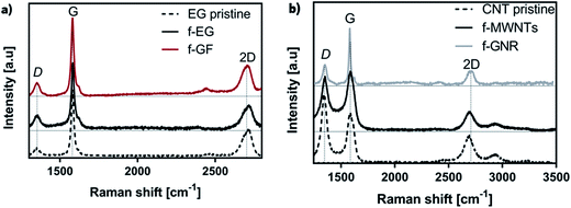 | ||
| Fig. 1 The Raman spectra obtained of (a) pristine EG, f-EG and f-GF and (b) pristine MWNTs, f-MWNTs and f-GNR. | ||
The first peak near 1342 cm−1 (D band) is due to the presence of sp3 carbon atoms, indicating the presence of defects in the hexagonal sp2 carbon lattice of graphene. The second peak near 1580 cm−1 (G band) results from in-plane vibration of the ordered sp2 bonded carbon atoms.45,46 The intensity ratio between D and G peaks (measured as the ratio of the D and G peak areas, ID/IG) has been used as a method to quantify the increase in disorder caused by covalent chemical modification, ripples, edges and charged impurities.47 The third peak near 2700 cm−1 (2D band) has almost the double frequency of the D band and results from the second order Raman scattering.48 This peak may be used to determine the number of stacked layers (up to 5) in n-layer graphene, by the analysis of its shape, width and position of the 2D band.47 Ferrari et al.49 reported that an increase in the number of layers originates a broader 2D band shifted to higher wavenumber. Pure graphene presents a single sharp 2D peak with higher intensity than the G band, while in pristine graphite a double structure of the 2D peak is observed, near 2720 cm−1.49,50 The Raman spectrum of MWNTs exhibits a 2D band shifted to 2683 cm−1 due to the strain induced by the nanotube curvature on the graphene layers.46
The analysis of the Raman spectra in Fig. 1a shows that the (ID/IG) for EG increased from 0.24 to 0.49 after functionalization (formation of f-EG), and this ratio further increased to 0.56 after f-EG exfoliation to form f-GF. The (ID/IG) increase may be related to the increase in sp3 carbon relative to the overall sp2 carbon content, due to the functionalization (from EG to f-EG) and then due to the exfoliation process that yields thinner f-GF flakes (from f-EG to f-GF, since only the outer f-EG graphene layers are functionalized).37 We also verified an increase in the (ID/IG) ratio after oxidation of EG in a previous work.38
The analysis of the Raman spectra in Fig. 1b shows that MWNTs exhibit an inverse behavior, with a decrease of (ID/IG) from 1.38 to 0.95 after functionalization (formation of f-MWNTs) and this ratio further decreased to 0.73 after f-MWNTs exfoliation to form f-GNR. The large (ID/IG) ratio observed for the pristine MWNTs is due to the large fraction of nanotubes containing defects. The functionalization process may select the MWNTs with higher sp2 carbon content, since it is based on a cycloaddition to sp2 carbon, thus forming f-MWNTs with lower (ID/IG) than the overall pristine MWNTs in spite of the covalent functionalization of their surface. In a previous work, a similar decrease in the (ID/IG) ratio was observed after permanganate oxidation of the same grade of MWNTs.38 The f-GNR that result from unzipping of the outer graphene layer of the f-MWNTs is a two-dimensional material with a Raman spectrum that is similar to that of the graphene derivatives in Fig. 1a.
The downshift of the 2D band from 2718 cm−1 (EG) to 2704 cm−1 (f-GF) and the higher symmetry of this band for f-GF relative to EG and f-EG supports the few-layer nature of f-GF.49 Regarding the spectra of f-GNR, the upshift of the 2D band position from 2683 cm−1 (MWNTs) to 2695 cm−1 is consistent with the absence of MWNTs and formation of few-layer functionalized graphene nanoribbons.49 Similar results were also obtained by Cunha et al.51
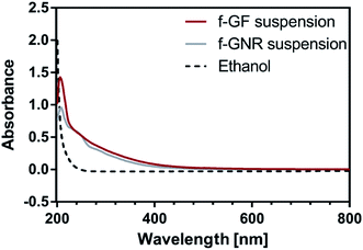
Regarding the UV-Vis spectra of f-GF suspension, it also presents a maximum absorbance at 250 nm, attributed to π → π* transitions.53
The concentration of the functionalized few-layer graphene suspensions produced are presented in Table 1, as well as the % yield of the exfoliation process.
| Suspension | [C]i of functionalized precursor [mg mL−1] | [C] of functionalized graphene in suspension [mg mL−1] | Yield [%] |
|---|---|---|---|
| f-GF | 1.000 | 0.037 | 3.700 |
| f-GNR | 1.000 | 0.033 | 3.300 |
Table 1 shows that both f-EG and f-MWNTs yield suspensions with a reasonable concentration of f-GF and f-GNR. The resultant suspensions of functionalized graphene were concentrated for the production of the FS, which requires large volumes of f-GF and f-GNR with a concentration of 0.25 mg mL−1.
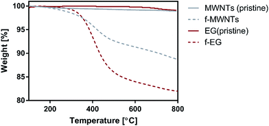 | ||
| Fig. 3 The TGA curves obtained for pristine EG and f-EG (red lines), and for pristine MWNTs and f-MWNTs (gray lines). | ||
The TGA results show that f-MWNTs and f-EG present thermal degradation curves with similar shape. The onset of thermal degradation is observed at a lower temperature for f-MWNTs, however their overall weight loss at 800 °C is smaller than that of f-EG. The pristine materials, EG and MWNTs, are thermally stable along the temperature range analyzed, as expected for pristine materials with low contamination level.54,55
The weight loss measured for the functionalized materials is due to the thermal degradation of the chemical groups bonded, indicating the successful functionalization of MWNTs an EG. f-EG and f-MWNTs exhibit a weight loss of 18.1 wt% and 11.3 wt%, respectively, at 800 °C.
3.2. In situ build-up if the multilayered films
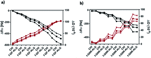
After characterization of both types of functionalized graphene (f-GNR and f-GF) and since they were stable in suspension, their potential to be assembled by LbL was evaluated. For that, QCM-D was used to monitor in situ the deposition of the various materials layers – Fig. 4.The buildup of 6 bilayers is depicted through the variation of the normalized frequency (Δf/ν) and dissipation (ΔD) of the 3rd, 5th and 7th overtone for (CHI/f-GF-ALG)6 and (CHI/f-GNR-ALG)6, Fig. 4a and b, respectively. In both cases, it can be observed that Δf decreases with the injection of CHI and f-GF or f-GNR-ALG, which means that the mass of these materials was adsorbed on the surface of the crystal at each deposition step. Comparing both (CHI/f-GF-ALG)6 and (CHI/f-GNR-ALG)6, a strong adsorption was verified for the films containing f-GF. This fact is possibly related to a stronger interaction between f-GF-ALG and CHI when compared with f-GNR-ALG and CHI. Regarding ΔD, it can be observed that is increasing with the injection of CHI and f-GF or f-GNR-ALG in both cases. ΔD gives an indirect indication of the film's viscoelastic properties. Thus, such ΔD increase demonstrates that the assembly of the multilayer film is not rigid and exhibits the typical viscoelastic behavior of polymeric systems. Due to the obtained results, the adsorption behavior does not obey to the Sauerbrey equation, confirming the viscoelastic character of these films.
The experimental results were modulated using the Voigt model, in order to estimate the thickness, shear modulus, and viscosity of the produced films. By assuming ρs = 1000 kg m−3, ηs = 0.001 kg m−1 s−1 and ρL = 1200 kg m−3, it was possible to estimate the thickness of the films as a function of adsorbed layers. As expected, Fig. 5 shows that the thickness of both films increases as the adsorbed layers increase. A thickness of 125 nm and 113 nm was estimated for (CHI/f-GF-ALG)6 and (CHI/f-GNR-ALG)6, respectively. These estimated values are based on the assumption that the adsorbed layers have a uniform thickness.
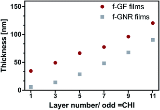 | ||
Fig. 5 Evolution of thickness of ( ) (CHI/f-GF-ALG)6 and ( ) (CHI/f-GF-ALG)6 and ( ) (CHI/f-GNR-ALG)6 films as a function of the layers deposited calculated based on the Voigt model. ) (CHI/f-GNR-ALG)6 films as a function of the layers deposited calculated based on the Voigt model. | ||
In addition to the thickness, the viscosity and the shear modulus were also estimated under the same aforementioned assumptions used for thickness – Fig. 6. It can be seen that both properties are increasing while the buildup of the films is occurring for both (CHI/f-GF-ALG)6 and (CHI/f-GNR-ALG)6. These results are similar to those reported in other studies which are related to the deposition of viscoelastic films.41,56
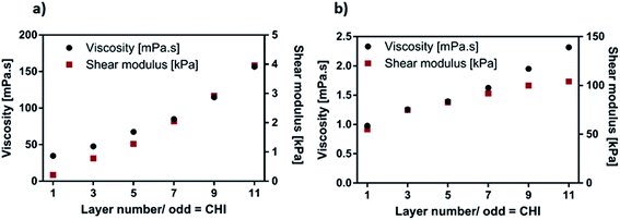 | ||
Fig. 6 Viscosity ( ) and shear modulus ( ) and shear modulus ( ) of (a) (CHI/f-GF-ALG)6 and (b) (CHI/f-GNR-ALG)6 film as a function of the layers deposited calculated with the Voigt model. ) of (a) (CHI/f-GF-ALG)6 and (b) (CHI/f-GNR-ALG)6 film as a function of the layers deposited calculated with the Voigt model. | ||
3.3. Scanning electron microscopy
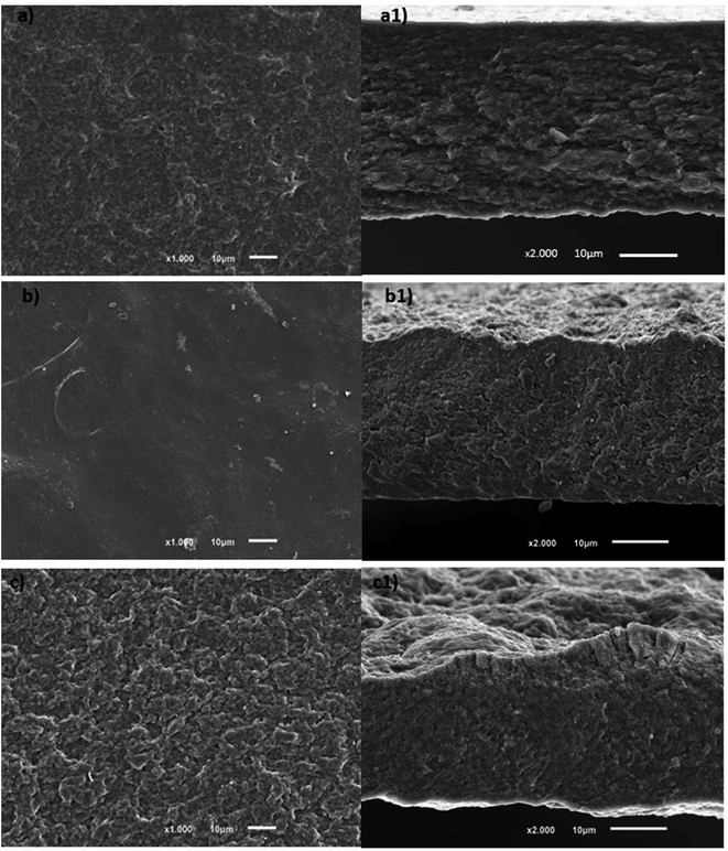
The morphology of the upper side (last layer produced) of the FS films as well as their cross-section were analyzed by SEM. All the films were easily removed from the PP substrate and demonstrated an easy handling. Only the upper side was evaluated since the lower side, which is in contact with the substrate, was previously reported by us and concluded that leads to smoother surfaces than the upper side of control films57 or the upper side of films containing graphene.38The obtained results of the surface morphology of the control film, Fig. 7a, are similar to those reported in a previous work.57 At a microscale, comparing (CHI/ALG)200 and (CHI/f-GF-ALG)200, it is observed that the addition of f-GF resulted in less porous and smoother films – see Fig. 7a and b, as also confirmed by AFM (see Fig. 8). Concerning the FS films with f-GNR, Fig. 7c, they show less porosity than the control ones and are rougher, as also confirmed by AFM (see Fig. 8).
Concerning the cross-section of graphene films (f-GF and f-GNR films), they are represented in Fig. 7b1 and c1, respectively. All cross-sections exhibited wrinkle-like structures. However, this seems to be emphasized by the presence of functionalized graphene, since the control film is more look-alike a layered structure (Fig. 7a1). Besides, the cross-section of f-GF films shows a much denser structure than that of f-GNR films. This can be related to a much stronger interaction between CHI and f-GF than CHI and f-GNR, which could result in an enhancement of the mechanical properties, as suggested by Han et al. for CHI/GO composites.58 Moreover, in the SEM images of both graphene FS films, no exposed f-GF nor f-GNR sheets were found, which accentuates a strong interaction with the surrounding polymers. Such behavior was also found by Li et al. with genipin-cross-linked CHI/GO composites.59
All the produced films show some porosity, which is an important characteristic for biomedical applications. Indeed, any scaffold for biomedical applications requires a porous structure for transporting oxygen, nutrients and waste metabolites in and out of the material without compromising its mechanical stability.32,57,60,61
3.4. Atomic force microscopy imaging
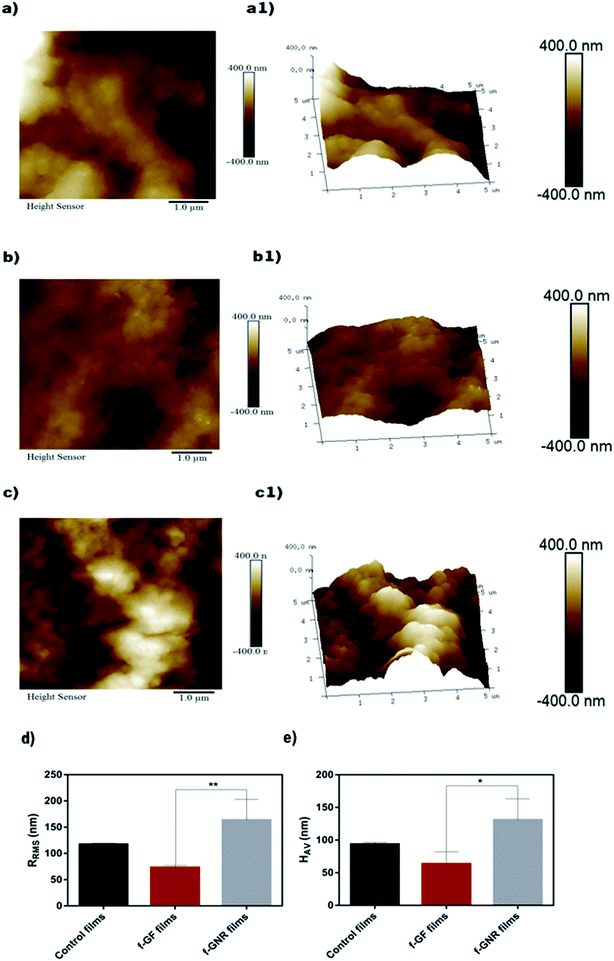
The 2D and 3D surface topographies of the upper side of the films were imaged using AFM – Fig. 8. The root-mean-square deviation values of the surface roughness (RRMS) for the region represented in Fig. 8a–c are presented in Fig. 8a.It was previously reported by us that the substrate side of FS films (in contact with CHI) usually leads to flatter surfaces than their upper side, presenting a roughness of 49 ± 15 nm.57
Regarding the RRMS of the upper side of control films, they present a moderate roughness of 117 ± 2 nm. This moderate roughness may be explained by the significant presence of some polymeric loops and tails, producing rough surface areas.62 When f-GF and f-GNR were incorporated into the polymeric matrix, some changes were visualized. Regarding (CHI/f-GF-ALG)200 films, a decrease in the RRMS is verified, comparing to the control ones, as visible from Fig. 8b and b1, where the FS evidenced a roughness value of 75 ± 3 nm. This effect may be explained by the flat topography characteristic of graphene-based materials. Opposite results were obtained in a previous work when o-GF with CHI and ALG was used in multilayered FS films.38
On the other hand, the (CHI/f-GNR-ALG)200 FS films exhibited the highest RRMS value of 164 ± 39 nm, as visible from Fig. 8c and c1. This was an expected behavior because, similar to CNTs, nanoribbons easily bend or present a twisted morphology, which may result in bundles structures.62 Similar results were obtained with GO by Gudarzi et al.63 as well as by us in a previous work,38 in which an increase in the RRMS was verified when o-GNR was used in the polymeric multilayered films.
Considering the potential biomedical application of FS films with f-GF and f-GNR, it should be noted that roughness is related to cell adhesion. Indeed, generally smoother surfaces exhibit lower cell adhesion than rougher surfaces.61 Thus, the higher roughness of (CHI/f-GNR-ALG)200 films may benefit the cell adhesion and proliferation. Biological assays confirmed this feature (Section 3.11 – Fig. 15). The presence of f-GNR increased the surface roughness and clearly enhanced both the cell adhesion and proliferation of these FS films when compared with the ones with f-GF.
The average height (HAV) values are shown in Fig. 8e). The HAV values range from 55 to 131 nm, being the lowest value for the (CHI/f-GF-ALG)200 FS and the highest one for the (CHI/f-GNR-ALG)200 film. It is possible to see that these values are near to the RRMS ones, which indicates that the roughness is constant along the FS film.
3.5. Thermogravimetric analysis
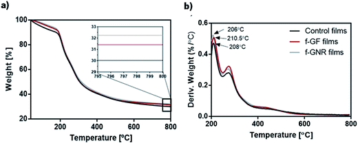
TGA analysis was performed in order to evaluate the thermal stability and the weight composition of the FS films produced. The results are illustrated in Fig. 9a and b. It can be seen that both films with graphene present a similar thermal stability compared with the control one when heated up to 800 °C under inert atmosphere, which means that the thermal stability is not affected by the presence of functionalized graphene. The initial weight loss below 200 °C is mostly related to the elimination of strongly adsorbed water and it slightly decreases in the presence of f-GF or f-GNR. The major weight loss was verified in the temperature range from 200 °C to 360 °C, due to the decomposition of the polymeric materials as well as the functional groups of f-GF or f-GNR. Similar behaviors were reported by Wang et al.64 for composites with CHI and graphene derivatives, Ionita et al.65 for ALG and GO composites and for CHI/ALG with o-GF or o-GNR composites.38 It is observed that the weight loss tends to stabilize above 600 °C, leaving a residual carbonaceous material from the thermal degradation of f-GF, f-GNR and from the polymer carbon backbone. As shown in Fig. 9a, the films containing f-GNR and f-GF present a slightly higher residual weight relative to the control ones. In fact, the incorporated graphene derivatives undergo a small weight loss corresponding to the degradation of the functional groups bonded to their surface, leaving the graphene material intact, which is characterized by high thermal stability under inert atmosphere. The residual weight of the (CHI/f-GF-ALG)200 and (CHI/f-GNR-ALG)200 films is approximately 31.4 wt% and 32.2 wt%, respectively. The difference between the residual weight measured from f-GF films and the control films (without graphene) was approximately 1.40 wt% while for f-GNR films, this difference was about 2.20 wt%. Considering that, at 800 °C, f-EG and f-MWNTs presented a residual weight of about 81.9 wt% and 88.7 wt% respectively (Fig. 3), the weight content of f-GF and f-GNR in the FS was estimated to be approximately 1.7 wt% and 2.5 wt%, respectively.3.6. Water contact angle measurements
In order to evaluate the wettability of the surfaces of all produced FS films, water contact angle measurements were performed. Only the upper side of each condition was evaluated – see Fig. 10. Regarding the control film, the upper side corresponds to ALG side and shows a WCA of 103 ± 0.6°, i.e. around 100°. Similar results were also obtained in a previous work for CHI/ALG films.32 Comparing the upper side of the (CHI/f-GF-ALG)200 and (CHI/f-GNR-ALG)200 FS, they present WCA values of 95.3 ± 0.4° and 92.7 ± 0.7°, respectively, which means that the presence of both functionalized graphene flakes and graphene nanoribbons confers significant differences in terms of wettability when compared to the control film. Indeed, both f-GF films and f-GNR films show a decrease in the WCA, which means that both FS films although remaining hydrophobic, they became more hydrophilic when functionalized graphene was added. This behavior was also verified by other works.66 Eventually, the functional groups of modified graphene or even the surface morphology turn these FS films more hydrophilic than the control film.66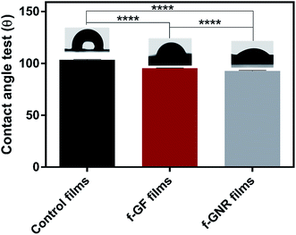 | ||
| Fig. 10 Water contact angle measurements with representative images for the upper side of each produced condition. Significant differences were state for p < 0.0001(****). | ||
Regarding the down side of FS films, in all cases, is the same material, CHI, so the same behavior is expected. The WCA of CHI side was already extensively reported and presents a WCA around 100°. In a previous study, we already reported a WCA of 100° in CHI/ALG multilayered films, too.32
3.7. Swelling ability studies
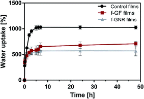
The swelling behavior of the produced FS was evaluated during 48 h in PBS at 37 °C. The obtained results are illustrated in Fig. 11. Regarding the control films, the results show that they attained the equilibrium after 5 h, reaching a maximum swelling of approximately 1028%. On the other hand, it is verified that the incorporation of both forms of functionalized graphene in the polymeric matrix reduces the water uptake (WU). Besides, more time is necessary to achieve the WU equilibrium, especially for the FS films containing f-GF. Similar results were obtained in multilayered FS films based on GO with ALG and CHI.38 Both f-GF and f-GNR films attained a maximum swelling of about 707% and 571%, respectively. This behavior may be related to the strong interfacial adhesion between the functionalized graphene and the polymeric matrix, which results in lower space for water storage capacity and diffusion, as was suggested by other authors.59,65 Since the WU decreases, these strong interactions between functionalized graphene and natural polymers seem to have more impact in their swelling ability than the hydrophilic nature of multilayered films. So, the incorporation of both types of functionalized graphene in CHI/ALG films seems to be an adequate strategy to control the swelling behavior, replacing the cross-linking methods. This behavior turns graphene-based composites promisors for application in heart valves or skin scaffolds as suggested in literature.593.8. Degradation studies
When a biomaterial is implanted in the human body the degradation rate of this biomaterial is one of the most important features, since the formation of the new tissue should match with the degradation of the material. Therefore, the biomaterial must be degrade only after appropriately completing its function.67,68 The degradation behavior of all produced FS films were assessed and are presented in Fig. 12.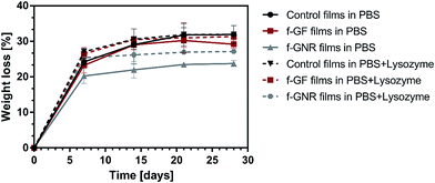 | ||
| Fig. 12 Degradation behavior of control films (black line), f-GF films (red line) and f-GNR films (gray line) when immersed in PBS and PBS with lysozyme over a period of 28 days at 37 °C. | ||
The weight-loss of f-GF, f-GNR and control films was caused by non-enzymatic hydrolysis and enzyme-catalysed hydrolysis, which are two common degradation processes that occur in natural polymers.67,68 For the enzyme-catalyzed hydrolysis evaluation a lysozyme solution was used, which is the main enzyme involved in the degradation of chitin derivatives such as CHI. It is present in human serum in concentrations around 7–13 mg L−1.69 For convenience, the maximum concentration was employed during this study.
Fig. 12 presents the degradation behavior of f-GF, f-GNR and control films when immersed in both PBS and PBS + lysozyme during 7, 14, 21 and 28 days.
Independently of the solution used, the degradation was more pronounced in the first seven days for all the studied films. At 7 days, when immersed in PBS medium, it was observed that the control film reached a higher weight loss than the other formulations. The weight loss was around 24%, 23% and 20% for the control film, (CHI/f-GF-ALG)200 and (CHI/f-GNR-ALG)200 FS, respectively. Moreover, a higher weight loss was verified for the same period when the samples were incubated in the PBS + lysozyme solution where a value of 27%, 26% and 25% was verified for the control film, (CHI/f-GF-ALG)200 and (CHI/f-GNR-ALG)200 FS, respectively. According to Justin et al.70 this major initial degradation in PBS + lysozyme may be attributed to the lysozyme reaction to the abundant CHI chains containing at least 3 acetyl units.
After 7 days of degradation in both solutions, it is clearer the higher weight loss of the control films, comparing to the film with functionalized graphene. At the end of the degradation study, 28 days, a weight loss of about 32%, 29% and 24% was achieved for the control film, (CHI/f-GF-ALG)200 and (CHI/f-GNR-ALG)200 FS, respectively with samples immersed in PBS. For the same period of time but with the samples soaked in PBS + lysozyme solution, a weight loss of about 32%, 31% and 27% was found for the control FS, (CHI/f-GF-ALG)200 and (CHI/f-GNR-ALG)200 FS, respectively. In general, it was verified that the control film presented a higher weight loss than the films containing f-GF and f-GNR, either in PBS or PBS + lysozyme medium. These results indicate that the incorporation of f-GF and f-GNR seems to induce a greater resistance to degradation. This behavior may be related with the water uptake capability of the films. Indeed, f-GF and f-GNR films present lower capability to swell and lower quantities of PBS and enzyme enter into the polymeric matrix, which results in lower weight loss, either by hydrolysis or by enzyme-hydrolysis action.59 Li et al. also observed a greater resistance to enzymatic degradation by increasing GO content.59
3.9. Dynamical mechanical analysis
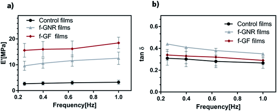
DMA is an adequate technique for characterizing the mechanical/viscoelastic properties of biomaterials since it can use test conditions that closely simulate the physiological environment.32DMA experiments were performed in order to evaluate the effects of the incorporation of functionalized graphene on the mechanical/viscoelastic properties of CHI/ALG FS films. Fig. 13a) presents the variation of the storage modulus, E′ along the frequency, from 0.1 to 1 Hz (physiological frequencies). For all produced films, it is verified that E′ increases with frequency, which is a particular behavior of viscoelastic materials.71 Such behavior was already verified in previous works for the control film.72,73 The incorporation of f-GF and f-GNR resulted in an increase of their stiffness which is a typical behavior verified in other studies regarding graphene-reinforced composites with CHI,74 ALG75 and with a CHI/ALG matrix38 in which it was found that, even for an amount of graphene as low as 0.1 wt% an increase in stiffness of approximately 2 times was verified. In this work, such increase in stiffness is more marked for the films containing f-GF. Indeed, Fig. 13a shows that the addition of f-GF results in a higher E′, reaching values 6.6 times higher than the control film while the addition for f-GNR generated values 3.8 times higher than the control films. Similar results were obtained in a previous work with FS films composed of CHI, ALG and GO.38 In the water uptake experiments it was verified that the control films had the higher ability to swell (about 1000%), in which more water was able to enter in the polymeric matrix leading to molecular mobility and thus, softening the films. Although a higher water uptake was verified for the (CHI/f-GF-ALG)200 (about 700%) than the (CHI/f-GNR-ALG)200 FS (about 600%), it is verified that the former ones are stiffer. This could be ascribed to the less porous structure of (CHI/f-GF-ALG)200 films as verified by SEM.
The loss factor, tan![[thin space (1/6-em)]](https://www.rsc.org/images/entities/char_2009.gif) δ it is the ratio of the amount of energy dissipated by viscous mechanisms relative to energy stored in the elastic component. It is a measure of energy loss and provides information about the damping properties of the films.76 The variation of tan
δ it is the ratio of the amount of energy dissipated by viscous mechanisms relative to energy stored in the elastic component. It is a measure of energy loss and provides information about the damping properties of the films.76 The variation of tan![[thin space (1/6-em)]](https://www.rsc.org/images/entities/char_2009.gif) δ as a function of the frequency is presented in Fig. 12b. Overall, all the produced FS flms present the same behavior. (CHI/f-GNR-ALG)200 films exhibited slightly higher tan
δ as a function of the frequency is presented in Fig. 12b. Overall, all the produced FS flms present the same behavior. (CHI/f-GNR-ALG)200 films exhibited slightly higher tan![[thin space (1/6-em)]](https://www.rsc.org/images/entities/char_2009.gif) δ values, indicating that such films possess a slightly higher capacity to dissipate energy. This could be the result of the larger area covered by the interface between the polymeric matrix and the particles for the former composite, that could contribute more for the dissipation of mechanical energy.76
δ values, indicating that such films possess a slightly higher capacity to dissipate energy. This could be the result of the larger area covered by the interface between the polymeric matrix and the particles for the former composite, that could contribute more for the dissipation of mechanical energy.76
tan![[thin space (1/6-em)]](https://www.rsc.org/images/entities/char_2009.gif) δ exhibit higher values at low frequencies, and close to 0.3 around 1 Hz (biological frequency) thus, indicating the viscoelastic character of the produced FS films. DMA and specifically this parameter are important when considering the potential of the developed FS films for biomedical application. A biomaterial is subjected to periodic loads in many situations, for example, the biomaterials for cardiovascular applications experiment the pulsed blood pressure. Besides, the viscoelastic character of these films has particular interest since living tissues and their biological constituents also exhibit a viscoelastic behavior at certain stimuli, when subjected to mechanical solicitations.77
δ exhibit higher values at low frequencies, and close to 0.3 around 1 Hz (biological frequency) thus, indicating the viscoelastic character of the produced FS films. DMA and specifically this parameter are important when considering the potential of the developed FS films for biomedical application. A biomaterial is subjected to periodic loads in many situations, for example, the biomaterials for cardiovascular applications experiment the pulsed blood pressure. Besides, the viscoelastic character of these films has particular interest since living tissues and their biological constituents also exhibit a viscoelastic behavior at certain stimuli, when subjected to mechanical solicitations.77
3.10. Electrical resistivity measurements
The electrical resistivity of the FS films was determined by measuring the current that passes through the control film and the films containing f-GF and f-GNR (volume resistivity) in the voltage range between −5.0 and 5.0 V, see Fig. 14. It was observed that the incorporation of f-GF and f-GNR in the polymeric matrix led to a decrease in the electrical resistivity from 3.00 × 10¹² Ω m to 1.66 × 10¹⁰ Ω m and 2.25 × 10⁹ Ω m, respectively. Several studies report a decrease of electrical resistivity in composites with graphene or graphene derivatives as fillers.78–82 For instance, Li and co-workers reported a similar trend for the resistivity of GO/polystyrene composites containing ≈2 wt% and 2.5 wt% of GO.83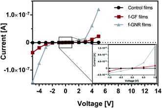 | ||
| Fig. 14 I–V curves obtained for the control, f-GF and f-GNR films between −5.0 V and 5.0 V with inset showing a magnification for voltages between −1.0 V and 1.0 V. | ||
The structure of the films produced is obtained by the deposition of two polymer layers in which one of them is combined with graphene. The low graphene content and the layered morphology, where an insulating polymer alternates with a polymer/graphene composite, limits the volume resistivity measured perpendicular to the layer direction. Although the f-GF and f-GNR containing FS films still present a resistive behavior, their electrical resistivity decreased by two and three orders of magnitude, respectively, which is a promising indication for the production of conductive films with higher graphene content.
3.11. Biological assays
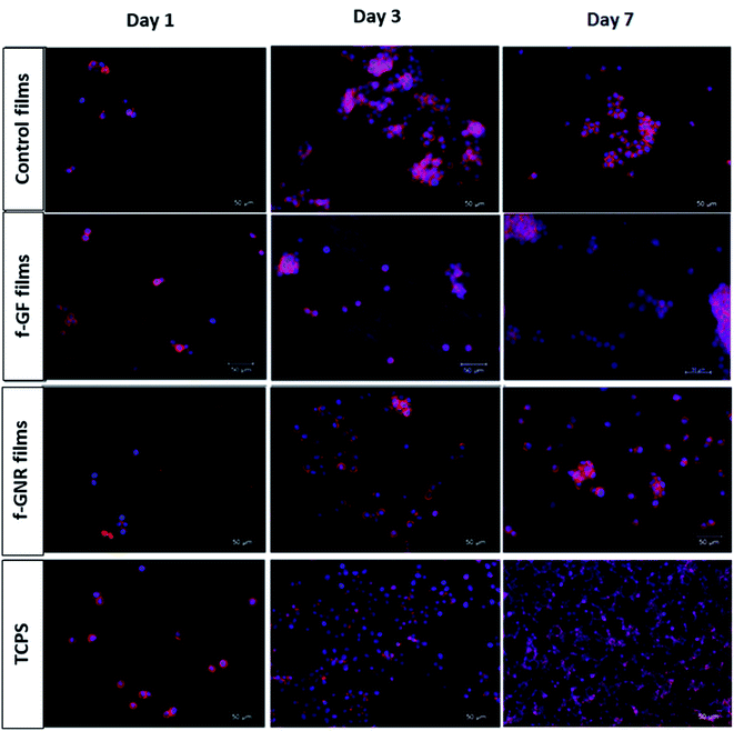
The cytocompatibility of the produced FS films was evaluated through in vitro culture studies by using L929 fibroblasts cells during 1, 3 and 7 days.To understand how cells adhered to the films and to observe their morphology, a DAPI–phalloidin test was performed – see Fig. 15. Comparing all the formulations, it can be noticed that cells behave quite differently for each condition. Although presenting a round shape on day 1, the cells started to adhere to the FS surface. Comparing all the formulations, the (CHI/f-GNR-ALG)200 films and TCPS presented more cells attached on its surface than the (CHI/f-GF-ALG)200 films and the control ones. After 3 days, although an increase in cell number was verified for all conditions, the (CHI/f-GF-ALG)200 films were the ones where the increase was not pronounced. Regarding the cell morphology, cells are better spread and revealed an elongated shape morphology for the (CHI/f-GNR-ALG)200 FS films and TCPS. In the case of (CHI/f-GF-ALG)200 films, the cells were more round than the other conditions and, the cells on the surface of the control film even formed some agglomerates. At day 7, the cell density increased for all conditions studied. Some cells on the control and on the f-GF film start to change their shape morphology, being more elongated. Regarding the cell morphology of the (CHI/f-GNR-ALG)200 films, they revealed a comparable morphology and behavior with TCPS. Cell attachment to hydrophilic surfaces occurs more readily and more strongly than to hydrophobic ones.84 The increase in surface roughness and the subsequent increase in surface area are important features to enhance cell attachment, independently of the cell type as was verified in other previous work.85 Indeed the surface of (CHI/f-GNR-ALG)200 films presents lower water contact angle and higher roughness than that of (CHI/f-GF-ALG)200 films.
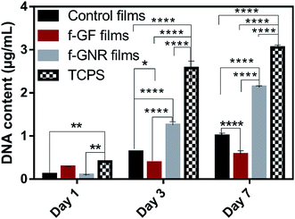
DNA quantification was used to assess the cell proliferation over a period of 7 days and the results are presented in Fig. 16. All the tested conditions presented an increase in cell proliferation, over the time period of the experiments. At day 1, significant differences were found between TCPS and both control and f-GNR films (p > 0.01(**)). In contrast no significant differences were found between TCPS and (CHI/f-GF-ALG)200 films. At day 3, significant differences were found for TCPS in relation to all the others conditions (p > 0.0001(****)). Besides, for the same period of time, (CHI/f-GNR-ALG)200 films exhibited significant increase in relation to both control and f-GF FS (p > 0.0001(****)). Also, the control films proliferated more than the (CHI/f-GF-ALG)200. At day 7, TCPS exhibited the same differences as the ones verified at day 3. In addition, f-GNR films presented significant differences when compared with both control and f-GF films (p > 0.0001(****)). It was also verified that the L929 cells proliferated more on the control film than on the (CHI/f-GF-ALG)200 film.
Overall, the biological assays demonstrated that the presence of f-GF and f-GNR in the polymeric matrix lead to different effects on L929 cell behavior. When f-GNR is present, an enhancement in terms of adhesion and cell proliferation was verified comparing to both control and f-GF films. Overall, the presence of both f-GF and f-GNR in the polymeric matrix enhanced the biological behavior of L929 cells. The better cytocompatibility of the (CHI/f-GNR-ALG)200 FS films may be related to their lower hydrophobicity and higher roughness. Other works reported an enhanced cell behavior when graphene were included in the polymeric matrix.38,82,86
4. Conclusions
(CHI/f-GF-ALG)200 and (CHI/f-GNR-ALG)200 FS films were successfully produced through LbL assembly. The incorporation of f-GF and f-GNR imparts distinctive properties relative to the control FS films. TGA analysis estimates an incorporation of approximately 1.7 wt% of f-GF and 2.5 wt% of f-GNR in the FS films. Both FS films presented lower porosity than the control ones. The incorporation of f-GF led to FS films with lower roughness while an opposite effect was observed with the incorporation of f-GNR. Both graphene reinforced FS films revealed the enhancement of the storage modulus, the (CHI/f-GF-ALG)200 FS films reaching the higher stiffness. A decrease in water contact angle was observed with the incorporation of f-GF and f-GNR, although both films remain hydrophobic. Besides, the resistance to degradation by hydrolysis and enzymatic action was enhanced in both FS films containing the functionalized graphene while the swelling ability decreased. Electrical measurements revealed that the incorporation of 1.7 and 2.5 wt% of f-GF and f-GNR, respectively, in the (CHI/f-GF-ALG)200 and (CHI/f-GNR-ALG)200 FS films induced a decrease of the electrical resistivity by two and three orders of magnitude, respectively. The biological assays with L929 cells revealed that all the produced FS films were cytocompatible and, in particular, the L929 were able to proliferate more on the surface of the (CHI/f-GNR-ALG)200 films.The results obtained in this work demonstrate the production of FS films containing graphene derivatives, (CHI/f-GF-ALG)200 and (CHI/f-GNR-ALG)200, with promising properties for biomedical applications such as wound healing and tissue engineering of bone and cardiac tissues.
Acknowledgements
The authors acknowledge the Portuguese Foundation for Science and Technology (FCT) and the European program FEDER/COMPETE for the financial support through project LA ICVS/3Bs – 2015–2017, and for project PEst-C/CTM/LA0025/2013 (LA 25 – 2015–2017). This work was also financially supported by FCT through the scholarships SFRH/BPD/96797/2013 granted to Sofia G. Caridade, SFRH/BD/97606/2013 granted to Maria P. Sousa, and SFRH/BD/87214/2012 granted to Eunice Cunha.References
- E. P. Randviir, D. A. C. Brownson and C. E. Banks, Mater. Today, 2014, 17, 426–432 CrossRef CAS.
- P. Avouris and C. Dimitrakopoulos, Mater. Today, 2012, 15, 86–97 CrossRef CAS.
- T. Kuila, S. Bose, A. K. Mishra, P. Khanra, N. H. Kim and J. K. Lee, Prog. Mater. Sci., 2012, 57, 1061–1105 CrossRef CAS.
- K. S. Novoselov, S. V. Morozov, T. M. G. Mohinddin, L. A. Ponomarenko, D. C. Elias, R. Yang, I. I. Barbolina, P. Blake, T. J. Booth, D. Jiang, J. Giesbers, E. H. Hill and A. K. Geim, Phys. Status Solidi B, 2007, 244, 4106–4111 CrossRef CAS.
- C. Soldano, A. Mahmood and E. Dujardin, Carbon, 2010, 48, 2127–2150 CrossRef CAS.
- D. Galpaya, M. Wang, M. Liu, M. Motta, E. Waclawik and C. Yan, Graphene, 2012, 1, 30–49 CrossRef CAS.
- K. S. Novoselov, V. I. Fal'ko, L. Colombo, P. R. Gellert, M. G. Schwab and K. Kim, Nature, 2012, 490, 192–200 CrossRef CAS PubMed.
- S. Goenka, V. Sant and S. Sant, J. Controlled Release, 2014, 173, 75–88 CrossRef CAS PubMed.
- A. M. Pinto, I. C. Gonçalves and F. D. Magalhães, Colloids Surf., B, 2013, 111, 188–202 CrossRef CAS PubMed.
- H. Bai, C. Li and G. Shi, Adv. Mater., 2011, 23, 1089–1115 CrossRef CAS PubMed.
- Y. Zhang, T. R. Nayak, H. Hong and W. Cai, Nanoscale, 2012, 4, 3833–3842 RSC.
- S. P. Lonkar, Y. S. Deshmukh and A. A. Abdala, Nano Res., 2015, 8, 1039–1074 CrossRef CAS.
- C. Zhang and T. Liu, Chin. Sci. Bull., 2012, 57, 3010–3021 CrossRef CAS.
- R. Araújo, M. C. Paiva, M. F. Proença and C. J. R. Silva, Compos. Sci. Technol., 2007, 67, 806–810 CrossRef.
- M. C. Paiva, F. Simon, R. M. Novais, T. Ferreira, M. F. Proença, W. Xu and F. Besenbacher, ACS Nano, 2010, 4, 7379–7386 CrossRef CAS PubMed.
- M. C. Paiva, E. Cunha, E. P. Freitas, H. Rocha, M. F. Proença, N. M. Alves, J. F. Mano, M. Melle-Franco, F. L. Deepak, M. González-Debs and P. E. Lopes, presented in part at Carbon Materials for Ubiquitous and Sustainable Life, Korea, June, 2014 Search PubMed.
- V. Georgakilas, K. Kordatos, M. Prato, D. M. Guldi, M. Holzinger and A. Hirsch, J. Am. Chem. Soc., 2002, 124, 760–761 CrossRef CAS PubMed.
- M. Paiva, W. Xu, M. F. Proença, R. M. Novais, E. Lægsgaard and F. Besenbacher, Nano Lett., 2010, 10(5), 1764–1768 CrossRef CAS PubMed.
- V. Georgakilas, M. Otyepka, A. B. Bourlinos, V. Chandra, N. Kim, K. C. Kemp, P. Hobza, R. Zboril and K. S. Kim, Chem. Rev., 2012, 112(11), 6156–6214 CrossRef CAS PubMed.
- T. Kuila, S. Bhadra, D. Yao, N. M. Kim, S. Bose and J. H. Lee, Prog. Polym. Sci., 2010, 35(11), 1350–1375 CrossRef.
- A. Sionkowska, Prog. Polym. Sci., 2011, 36(9), 1254–1276 CrossRef CAS.
- M. Rinaudo, Prog. Polym. Sci., 2006, 31(7), 603–632 CrossRef CAS.
- F. Croisier and C. Jérôme, Eur. Polym. J., 2013, 49(4), 780–792 CrossRef CAS.
- M. Akili, M. Rafatullah, B. Salamatinia, A. Z. Abdullah, M. H. Ibrahim, K. B. Tan, Z. Gholami and P. Amouzgar, Carbohydr. Polym., 2014, 113, 115–130 CrossRef PubMed.
- T. Zerzopoulou, G. Z. Kyzas and D. N. Bikiaris, Materials, 2015, 652–683 CrossRef.
- I. Y. Kim, S. J. Seo, H. S. Moon, M. K. Yoo, I. Y. Park, B. C. Kim and C. S. Cho, Biotechnol. Adv., 2008, 26(1), 1–21 CrossRef CAS PubMed.
- K. Y. Lee and D. J. Mooney, Prog. Polym. Sci., 2012, 37(1), 106–126 CrossRef CAS PubMed.
- D. S. Morais, M. A. Rodrigues, T. I. Silva, M. A. Lopes, M. Santos, J. D. Santos and C. M. Botelho, Carbohydr. Polym., 2013, 95(1), 134–142 CrossRef CAS PubMed.
- J. Borges and J. F. Mano, Chem. Rev., 2014, 114(18), 8883–8942 CrossRef CAS PubMed.
- R. R. Costa and J. F. Mano, Chem. Soc. Rev., 2014, 43, 3453–3479 RSC.
- C. Picart, F. Caruso, J. Voegel and G. Decher, Layer-by-layer films for Biomedical Application, John Wiley & Sons, 2014 Search PubMed.
- J. M. Silva, S. G. Caridade, N. M. Oliveira, R. L. Reis and J. F. Mano, J. Mater. Chem. B, 2015, 3, 4555–4568 RSC.
- I. Armentano, M. F. Dottori, E. Fortunati, S. Mattioli and J. M. Kenny, Polym. Degrad. Stab., 2010, 95(11), 2126–2146 CrossRef CAS.
- K. Hu, D. D. Kulkarni, I. Choi and V. V. Tsukruk, Prog. Polym. Sci., 2014, 39, 1934–1972 CrossRef CAS.
- W. K. Chee, H. N. Lim, N. M. Huang and I. Harrison, RSC Adv., 2015, 5, 68014–68051 RSC.
- M. M. Barsan, M. David, M. Florescu, L. Ţugulea and C. M. Brett, Bioelectrochemistry, 2014, 99, 46–52 CrossRef CAS PubMed.
- L. Tang, X. Li, D. Du and C. He, Prog. Nat. Sci.: Mater. Int., 2012, 22(4), 341–346 CrossRef.
- D. Moura, S. G. Caridade, M. P. Sousa, E. Cunha, H. Rocha, J. F. Mano, M. C. Paiva and N. M. Alves, J. Mater. Chem. B, 2016, 2(47), 7718–7730 RSC.
- H. Rocha, MSc thesis, University of Minho, 2014.
- K. A. Mark, Biomacromolecules, 2003, 4(5), 1099–1120 CrossRef PubMed.
- N. M. Alves, C. Picart and J. F. Mano, Macromol. Biosci., 2009, 9, 776–785 CrossRef CAS PubMed.
- M. V. Voinova, M. Rodahl, M. Jonson and B. Kasemo, Phys. Scr., 1999, 59(5), 391 CrossRef CAS.
- M. E. Gomes, H. S. Azevedo, A. R. Moreira, V. Ellä, M. Kellomäki and R. L. Reis, J. Tissue Eng. Regener. Med., 2008, 2, 243–252 CrossRef CAS PubMed.
- S. Park, C. T. Hung and G. A. Ateshian, Osteoarthritis Cartilage, 2004, 12(1), 65–73 CrossRef CAS PubMed.
- Z. Ni, Y. Wang, T. Yu and Z. Shen, Nano Res., 2008, 1(4), 273–291 CrossRef CAS.
- L. Bokobza and J. Zhang, eXPRESS Polym. Lett., 2012, 6(7), 601–608 CrossRef CAS.
- Y. Zhu, S. Murali, C. Wai, X. Li, J. W. Suk, J. R. Potts and R. S. Ruoff, Adv. Mater., 2010, 22(35), 3906–3924 CrossRef CAS PubMed.
- V. Singh, D. Joung, L. Zhai, S. Das, S. I. Khondaker and S. Seal, Prog. Mater. Sci., 2011, 56(8), 1178–1271 CrossRef CAS.
- A. C. Ferrari, J. C. Meyer, V. Scardaci, C. Casiraghi, M. Lazzeri, F. Mauri, S. Piscanec, D. Jiang, K. S. Novoselov, S. Roth and A. K. Geim, Phys. Rev. Lett., 2006, 97(18), 1–4 CrossRef PubMed.
- Y. y. Wang, Z. h. Ni, T. Yu, Z. X. Shen, H. m. Wang, Y. h. Wu, W. Chen and A. T. S. Wee, J. Phys. Chem. C, 2008, 112(29), 10637–10640 CAS.
- E. Cunha, M. F. Proença, F. Costa, A. J. Fernandes, M. A. C. Ferro, P. E. Lopes, M. González-Debs, M. Melle-Franco, L. F. Deepak and M. C. Paiva, ChemistryOpen, 2015, 4, 115–119 CrossRef CAS PubMed.
- Y. Xu, Z. Liu, X. Zhang, Y. Wang, J. Tian, Y. Huang, Y. Ma, X. Zhang and Y. A. Chen, Adv. Mater., 2009, 21, 1275–1279 CrossRef CAS.
- W. W. Liu, J. N. Wang and X. X. Wang, Nanoscale, 2012, 4, 425–428 RSC.
- L. Sun and B. Fugetsu, Mater. Lett., 2013, 109, 207–210 CrossRef CAS.
- W. Zou, Z. Du, Y. Liu, X. Yang, H. Li and C. z. Zhang, Compos. Sci. Technol., 2008, 68(15–16), 3259–3264 CrossRef CAS.
- S. M. Notley, M. Eriksson and L. Wågberg, J. Colloid Interface Sci., 2005, 292(1), 29–37 CrossRef CAS PubMed.
- S. G. Caridade, C. Monge, F. Gilde, T. Boudou, J. F. Mano and C. Picart, Biomacromolecules, 2013, 14, 1653–1660 CrossRef CAS PubMed.
- D. Han, L. Yan, W. Chen and W. Li, Carbohydr. Polym., 2011, 83, 653–658 CrossRef CAS.
- J. H. Li, N. Ren, J. Qiu, X. Mou and H. Liu, Int. J. Nanomed., 2013, 8, 3415–3426 CrossRef PubMed.
- F. T. Zohora and A. Y. M. A. Azim, Eur. Sci. J., 2014, 10(21), 186–209 Search PubMed.
- C. S. Hajicharalambous, J. Lichter, W. T. Hix, M. Swierczewska, M. F. Rubner and P. Rajagopalan, Biomaterials, 2009, 30(23–24), 4029–4036 CrossRef CAS PubMed.
- M. Olek, J. Ostrander, S. Jurga, H. Möhwald, N. Kotov, K. Kempa and M. Giersig, Nano Lett., 2004, 4(10), 1889–1895 CrossRef CAS.
- M. M. Gudarzi and F. Sharif, eXPRESS Polym. Lett., 2012, 6, 1017–1031 CrossRef.
- X. Wang, H. Bai, Z. Yao, A. Liu and G. Shi, J. Mater. Chem., 2010, 20, 9032–9036 RSC.
- M. Ionita, M. A. Pandele and H. Iovu, Carbohydr. Polym., 2013, 94(1), 339–344 CrossRef CAS PubMed.
- J. Lee, H.-R. Chae, Y. J. Won, K. Lee, C. H. Lee, H. H. Lee, I. C. Kim and J. Lee, J. Membr. Sci., 2013, 448, 223–230 CrossRef CAS.
- R. L. Reis, N. M. Neves, J. F. Mano, M. E. Gomes, A. P. Marques and H. S. Azevedo, Natural-Based Polymers for Biomedical Applications, Woodhead Publishing, 2008 Search PubMed.
- M. E. Gomes and R. L. Reis, Int. Mater. Rev., 2004, 49(5), 261–273 CrossRef CAS.
- H. S. Azevedo and R. L. Reis, Understanding the enzymatic degradation of biodegradable polymers and strategies to control their degradation rate, in Biodegradable Systems in Tissue Engineering and Regenerative Medicine, ed. R. L. Reis and J. San Roman, FL CRC Press, Boca Raton, 2005, vol. 12, pp. 177–201 Search PubMed.
- R. Justin and B. Chen, Carbohydr. Polym., 2014, 103(1), 70–80 CrossRef CAS PubMed.
- K. P. Menard, Dynamic Mechanical Analysis: A practical introduction, CRC Press, 2008 Search PubMed.
- J. M. Silva, A. R. Duarte, S. G. Caridade, C. Picart, R. L. Reis and J. F. Mano, Tailored freestanding multi layered membranes based on chitosan and alginate, Biomacromolecules, 2014, 15, 3817–3826 CrossRef CAS PubMed.
- S. G. Caridade, C. Monge, J. Almodóvar, R. Guillot, J. Lavaud, V. Josserand, J. L. Coll, J. F. Mano and C. Picart, Acta Biomater., 2015, 15, 139–149 CrossRef CAS PubMed.
- H. L. Fan, L. Wang, K. Zhao, N. Li, Z. Shi, Z. Ge and Z. Jin, Biomacromolecules, 2010, 11, 2345–2351 CrossRef CAS PubMed.
- L. Nie, C. Liu, J. Wang, Y. Shuai, X. Cui and L. Liu, Carbohydr. Polym., 2015, 117, 616–662 CrossRef CAS PubMed.
- S. G. Caridade, E. G. Merino, N. M. Alves, V. Z. Bermudez, A. R. Boccaccino and J. F. Mano, J. Mech. Behav. Biomed. Mater., 2013, 20, 173–183 CrossRef CAS PubMed.
- J. F. Mano, R. L. Reis and A. M. Cunha, Dynamic Mechanical Analysis in Polymers for Medical Applications, in Polymer Based Systems on Tissue Engineering: Replacement and Regeneration, ed. R. L. Reis and D. Cohn, Springer, Netherlands, Amsterdam, 2002, vol. 86, pp. 139–164 Search PubMed.
- X. Y. Qi, D. Yan, Z. Jiang, Y. K. Cao, Z. Z. Yu, F. Yavari and N. Koratkar, ACS Appl. Mater. Interfaces, 2011, 3(8), 3130–3133 CAS.
- F. Wang, Y. Zhang, B. B. Zhang, R. Y. Hong, M. R. Kumar and C. R. Xie, Enhanced electrical conductivity and mechanical properties of ABS/EPDM composites filled with graphene, Composites, Part B, 2015, 83, 66–74 CrossRef CAS.
- T. N. Zhou, X. D. Qi and Q. Fu, eXPRESS Polym. Lett., 2013, 7, 747–755 CrossRef CAS.
- H.-B. Zhang, W. G. Zheng, Q. Yang, Y. Yang, J. W. Wang, Z. H. Lu, G. Y. Ji and Z.-Z. Yu, Polymer, 2010, 51, 1191–1196 CrossRef CAS.
- C. Silva, MSc thesis, University of Minho, 2016.
- W. Li, X. Z. Tang, H. B. Zhang, Z. G. Jiang, Z. Z. Yiu, X. S. Du and Y. W. Mai, Carbon, 2011, 49(14), 4724–4730 CrossRef CAS.
- T. A. Horbett, J. J. Waldburger, B. D. Ratner and A. S. Hoffman, J. Biomed. Mater. Res., 1988, 22(5), 383–404 CrossRef CAS PubMed.
- S. M. Oliveira, N. M. Alves and J. F. Mano, J. Adhes. Sci. Technol., 2012, 1–21 Search PubMed.
- J. Kim, Y. R. Kim, Y. Kim, K. T. Lim, H. Seonwoo, S. Park, S.-P. Cho, B. H. Hong, P. H. Choung, T. D. Chung, Y. H. Choung and J. H. Chung, J. Mater. Chem. B, 2013, 1, 933 RSC.
| This journal is © The Royal Society of Chemistry 2017 |

