 Open Access Article
A simple method to control the microstructure and properties of sol–gel silica antireflective coatings†
Yingying Sun‡
a,
Jiaxian Zheng‡a,
Rongchao Huanga,
Xinxiang Zhang *a,
Cuixia Chena,
Bo Jiang
 b,
Hanxian Chena,
Lianghong Yanc and
Wenbin Yang*b
aCollege of Materials Engineering, Fujian Agriculture and Forestry University, Fuzhou, 350002, China. E-mail: xxzhang0106@163.com; Fax: +86 591 83715175
bCollege of Chemistry, Sichuan University, Chengdu, 610064, China
cResearch Center of Laser Fusion, China Academy of Engineering Physical, Mianyang, 621900, China
First published on 22nd June 2017
Abstract
To control the microstructure and properties of sol–gel silica antireflective (AR) coatings, a simple PMHS (poly(methylhydrogen)siloxane) surface modification method was applied and investigated. This is accomplished simply by immersing the AR coating into the modifier solution containing PMHS, hexane and the Karstedt catalyst and then immediately withdrawing it at a desired withdrawal rate. A systematic study was carried out to investigate the effect of PMHS on the microstructure and optical, hydrophobic and mechanical properties of sol–gel silica AR coatings. It was found that PMHS surface modification greatly increased the hydrophobicity and mechanical properties of sol–gel silica AR coatings by increasing their water contact angles from 27.2° to about 120° and Young's modulus from 317 MPa to 482 MPa. Most importantly, the transmittance of AR coatings can be tailored well between 96.4% and 100% by controlling the PMHS chain length, PMHS concentration and withdrawal rate. Speculation and verification of the PMHS surface modification process was discussed in detail after SEM characterization and optical simulation by TFCalc™ software. Finally, with this simple method, a hydrophobic sol–gel silica AR coating with excellent transmittance of 99.9%, improved mechanical properties and AR stability was realized, which can find great applications in high power laser fusion systems.
1. Introduction
Antireflective (AR) coatings have been widely used in solar cells, optical filters, cameras and laser systems.1–5 Oblique-angle deposition,6,7 phase separation and etching,8,9 self-assembly of block copolymers,10 reactive twin-magnetron sputtering,11 the layer-by-layer deposition method12 and the sol–gel method13,14 were utilized to adjust the refractive index of AR coatings and hence the transmittance. Among these methods, the sol–gel process has become attractive due to its advantages of nearly 100% transmittance, low cost, large area deposition, large-scale production and easy control of film thickness and refractive index.15 More importantly, the laser-induced damage threshold (LIDT) of sol–gel silica AR coatings is two to three times higher than that of AR coatings prepared by the other methods, and therefore the sol–gel silica AR coating is irreplacable in high-powered laser fusion systems.16However, the sol–gel silica AR coating suffers from poor AR stability17,18 and mechanical strength.19,20 The sol–gel silica AR coating is porous and polar because it consists of a loose layer of hydrophilic silica particles that are randomly stacked on the optical substrate. Therefore, in the high-powered laser system, the sol–gel silica AR coating tends to absorb polar contaminants such as water and plasticizers of engineering materials from environment.17,18 The pollutants adsorbed in the pores of AR coatings will gradually increase the refractive index and hence decrease the transmittance. In addition, the sol–gel silica AR coatings are kept intact only by point contact forces between individual particles, and therefore the mechanical strength is quite weak.19,20
It is very desirable to overcome the poor AR stability of sol–gel silica AR coating. Because there are thousands of transmissive optics in high-powered laser system, a slight decrease in transmittance of individual optic will significantly decrease the total energy directed into the target chamber. To improve the AR stability of sol–gel silica AR coatings, surface modification,21–25 organic–inorganic hybrid (OIH) coatings from tetraethyl orthosilicate (TEOS) and organic precursors26–29 and OIH coatings from silica and polymers30–34 have been investigated.
The surface modification of sol–gel silica AR coating with hexamethyldisilazane (HMDS) was proposed and applied in National Ignition Facility (NIF).21 The HMDS surface modification of sol–gel silica AR coatings involved two steps, the initial treatment with ammonia and water vapor followed by treatment with HMDS. After HMSD surface modification, the hydroxyl groups on the surface of sol–gel silica AR coatings can be converted into the hydrophobic –Si(CH3)3 groups, and the AR stability can be significantly improved. However, the surface modification is time-consuming. OIH coatings from TEOS and organic precursors were prepared by using TEOS and organic precursors such as methyltrimethoxysilane (MTES) or dimethyldiethoxysilane (DDS) as co-precursors.28 The introduction of methyl groups greatly improved the hydrophobicity and hence the AR stability of sol–gel silica AR coatings. However, the “spring-back” phenomenon of hydrophobic groups in the OIH network would significantly increase the porosity and therefore decrease the refractive index of AR coatings.35 As the refractive index of AR coating decreases from 1.23 to 1.10, according to the Freshnel equation of R = (nc2 − ns)2/(nc2 + ns)2, the transmittance decreases from 100% to 98.3%,36 where nc and ns are the refractive index of AR coating and optical substrate. This is disadvantage to high power laser system because the transmittance of transmissive optics should be higher than 99.5%. OIH coatings from silica and polymer were prepared by adding ethanol-soluble polymer (such as polyvinyl butyral (PVB), polyvinyl alcohol (PVA) and polydimethylsiloxane (PDMS) with low molecular weight) into the silica sols.34 The increase in AR stability of this method is not as good as the above two methods. Also, the addition of polymer would increase the refractive index, which would also decrease the transmittance of AR coatings.
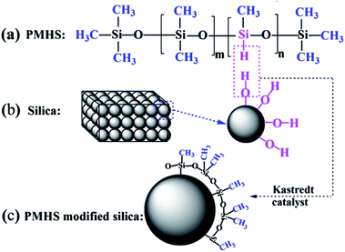
In our previous study, we reported a novel surface modification method for sol–gel silica AR coatings by using poly(methylhydrogen)siloxane (PMHS) as modifier.37 It has been demonstrated that the PMHS surface modification could control the transmittance and hydrophobicity of sol–gel silica AR coating. The chemical reaction principle of PMHS surface modification is simple and clear. PMHS chain bears reactive –Si–H groups and amounts of hydrophobic methyl groups. The dehydrogenation reaction occurs between –Si–H of PMHS chains and hydroxyl groups on the surface of silica particles. As a result, the quantity of hydroxyl groups decrease and the PMHS chains with low surface energy are grafted onto the AR coating, improving significantly the hydrophobicity and hence the AR stability of sol–gel silica AR coatings. However, the microscopic process of PMHS surface modification is the key factor to control the macro-properties of sol–gel silica AR coating. In this work, a systematical research was carried out to investigate the effect of PMHS on the microstructure, optical, hydrophobic as well as mechanical properties of sol–gel silica AR coatings. We also discussed the speculation and verification of PMHS surface modification process after SEM characterization and optical simulation by TFCalc™ software. In addition, this work also characterized quantitatively the nano-mechanical propertied of sol–gel silica AR coating by Bruker atomic force microscope (AFM) using PeakForce QNM scan mode. This is one of the significant contributions of this work to the sol–gel silica AR coating, because the characterization of mechanical properties of sol–gel silica AR coatings in the previous studies is quite qualitative or indirect.17,38,39 Most importantly, a systematic investigation was carried out to investigate the effect of PMHS surface modification on microstructure and properties of sol–gel silica AR coatings. Finally, with this simple method, hydrophobic sol–gel silica AR coating with excellent transmittance of 99.9%, improved mechanical property and AR stability was realized, which can find great application in high power laser fusion system.
2. Experimental section
2.1 Materials
Tetraethyl orthosilicate (TEOS) was purchased from Sigma-Aldrich. Ethanol and ammonia water were purchased from Sinopharm Chemical Reagent Co., Ltd. PMHS was purchased from Chengguang Research Institute of Chemical Industry (Chengdu, China). Poly(methylhydrogen)siloxane (PMHS) were named as 0.2PMHS, 1.0PMHS and 1.5PMHS as the hydrogen content is 0.2%, 1.0% and 1.5%, respectively.2.2 Preparation of silica sol and AR coating
17.9 mL TEOS, 175 mL ethanol, 4 mL H2O and 1.0 mL NH3·H2O was added into a 250 mL flask and then stirred for 2 h at 30 °C. The resultant sol was aged at 25 °C for 9 days. Before coating, the sol was carefully filtered through 0.22 μm PVDF filters. The BK7 glasses were cleaned with ethanol and then wiped carefully with cleanroom wipers. Finally, the silica AR coatings were coated onto the cleaned BK7 glass by dip-coating at the withdrawal rate of 100 mm min−1. The AR coatings were heated at 160 °C for 2 h.2.3 Surface modification of silica AR coatings
0.2PMHS, 1.0PMHS and 1.5PMHS were applied as modifier. Modifier solutions with PMHS contents of 0.00%, 0.25%, 0.50%, 1.00% and 1.50% were obtained by mixing PMHS, hexane, and Karstedt catalyst (platinum-1,3-divinyl-1,1,3,3-tetramethyldisiloxane) together. The content of Pt in modifier solution is about 20 ppm. The surface modification process is accomplished by dipping the silica AR coating into the modifier solutions and then immediately withdrawing out at the withdrawal rate of 50 mm min−1 and 100 mm min−1, respectively. The PMHS modified silica AR coatings were heated at 160 °C for 2 h.2.4 Characterization
The transmittance spectra were recorded with a UV-Vis spectrophotometer (Mapada, 3200). The theoretical transmittance spectra were modeled by TFCalc™ software (Nanjing Wavelab Software System Co. Ltd.). The water contact angles of the AR coatings were measured on Krüss DSA100. The cross-section SEM was performed using a SU8010 high-resolution SEM (Hitachi). The surface morphology, adhesion force and Young's modulus were characterized by Bruker atomic force microscope (AFM) using PeakForce QNM scan mode, in which the quantitative nano-mechanical properties can be mapped. The probe is TAP150A.3. Results and discussion
3.1 Effect of PMHS surface modification on optical properties
For high-powered laser fusion system, a feasible surface modification strategy of sol–gel silica AR coating should meet two requirements. One the one hand, the surface modification should not decrease the transmittance of modified AR coatings. The transmittance of AR coating in high power laser system should be nearly 100% (commonly higher than 99.5%). There are thousands of transmissive optics in high power laser system. According to eqn (1),36 each optical component creates optical reflection at the air-components surfaces. The optical reflection will not only confuse the target diagnostic but also obviously reduce the out putenergy. One the other hand, the surface modification should also not change the optical thickness obviously. AR coating used in high power laser system should have desired optical thickness (ncd) because, according to eqn (2),36 it determines the central wavelength. As the central wavelength is near to the wavelength of laser, the AR coating possesses the maximum transmittance. As the surface modification changes optical thickness obviously, the wavelength of maximum transmittance (λ0) will red-shifted obviously, which will significantly decrease the transmittance at the wavelengths of lasers.| λ0 = 4ncd | (1) |
| R = (nc2 − ns)2/(nc2 + ns)2 = (1 − T)/2 | (2) |
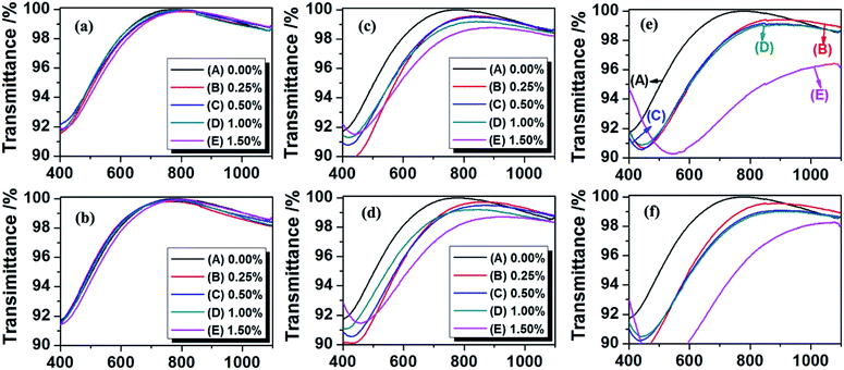
The effect of hydrogen content of PMHS, PMHS content in modifier solution and withdraw rate on the optical properties of AR coating was systematically investigated by a UV-Vis spectrophotometer. The transmittance spectra were shown in Fig. 1. The values of central wavelength and maximum transmittance at central wavelength were read from Fig. 1, and listed in Table 1. For 0.2PMHS modified AR coatings, at the withdraw rate of 50 and 100 mm min−1, the PMHS content has little effect on the central wavelength and the transmittance. As the PMHS content increased from 0.00% to 1.50%, the central wavelength increases slightly from 783 nm to 810 nm and from 783 nm to 808 nm, respectively, and the transmittance is almost unchanged (nearly 100%). For 1.5PMHS modified AR coatings, the PMHS content significantly affects the optical property of AR coatings. As shown in Fig. 2(e) and (f), the transmittance spectra were quite different as the PMHS content increased from 0.00% to 1.50%. At withdraw rate of 50 mm min−1, the central wavelength of 1.5PMHS modified AR coatings increased from 783 nm to 1073 nm, and the transmittance decreased from 100% to 96.4%. Finally, it can be concluded that the 0.2PMHS is the best candidate for surface modification of AR coating used in high power laser system.
| Coating speed | 0.2PMHS | 1.0PMHS | 1.5PMHS | |||||||||
|---|---|---|---|---|---|---|---|---|---|---|---|---|
| 50 mm min−1 | 100 mm min−1 | 50 mm min−1 | 100 mm min−1 | 50 mm min−1 | 100 mm min−1 | |||||||
| ncda and Ta | ncd | T | ncd | T | λ0 | T | λ0 | T | λ0 | T | λ0 | T |
| a The units for optical thickness and transmittance are nm and %. | ||||||||||||
| 0.00% | 783 | 100 | 783 | 100 | 783 | 100 | 783 | 100 | 783 | 100 | 783 | 100 |
| 0.25% | 798 | 99.9 | 760 | 99.8 | 833 | 99.6 | 869 | 99.7 | 853 | 99.4 | 849 | 99.6 |
| 0.50% | 814 | 99.9 | 776 | 99.9 | 822 | 99.5 | 876 | 99.5 | 888 | 99.1 | 901 | 99.1 |
| 1.00% | 799 | 99.9 | 756 | 99.9 | 841 | 99.2 | 841 | 99.2 | 905 | 99.1 | 903 | 99.0 |
| 1.50% | 810 | 99.9 | 808 | 99.9 | 892 | 98.8 | 921 | 98.7 | 1073 | 96.4 | 1047 | 98.2 |
3.2 Speculation and verification of PMHS surface modification process
As discussed before, the hydrogen content of PMHS and PMHS content in the modifier solution affected the optical properties of AR coating. To speculate the PMHS surface modification process, the chemical structure and the microstructure of the sol–gel silica AR coating should be took into account.| Porosity = 1 − (n2 − 1)/(nd2 − 1) | (3) |
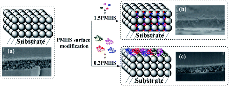 | ||
| Fig. 3 Schematic representation and cross-sectional SEM images of AR coating before and after PMHS surface modification (unmodified (a), 1.5PMHS modified (b) and 0.2PMHS modified (c) AR coatings). | ||
PMHS is a polymer in the form of flexible chain. The difference between the pore size and the chain length of PMHS is the key factor to predict whether the PMHS chains play a role of penetration or anti-penetration. Our previous study indicated that the average pore radius of sol–gel silica from nitrogen adsorption/desorption analysis is about 2.6 nm, which indicates the pore diameter of sol–gel silica AR coating is about 5.2 nm.41
The theoretical molecule weight of 0.2PMHS, 1.0PMHS and 1.5PMHS is calculated to be about 12![[thin space (1/6-em)]](https://www.rsc.org/images/entities/char_2009.gif) 036, 2416 and 1602, respectively, and then the length of extended chains is estimated to be about 47 nm, 10 nm and 7 nm, respectively. (See ESI:† theoretical calculation of molecule weight and estimation of chain length of PMHS). Actually, the flexibility of PMHS is good, and it would be in the manner of random coil nor extended chain in good solvent. The size of PMHS coil is much smaller than the estimated ones. Therefore, a schematic representation of microstructure change of AR coating before and after PMHS surface modification can be drew as Fig. 3 and contrasted with the SEM images.
036, 2416 and 1602, respectively, and then the length of extended chains is estimated to be about 47 nm, 10 nm and 7 nm, respectively. (See ESI:† theoretical calculation of molecule weight and estimation of chain length of PMHS). Actually, the flexibility of PMHS is good, and it would be in the manner of random coil nor extended chain in good solvent. The size of PMHS coil is much smaller than the estimated ones. Therefore, a schematic representation of microstructure change of AR coating before and after PMHS surface modification can be drew as Fig. 3 and contrasted with the SEM images.
Because the size of 1.5PMHS coil is smaller than that of pores in AR coating, the 1.5PMHS can penetrate fast into the pores. After the air in the pores being replaced by the PMHS, the refractive index of AR coating increased. With the increasing PMHS content in the modifier solution, more PMHS chains aggregated in the pore of AR coating, and the increment of refractive index is more remarkable. This explained well the significant change in optical properties of 1.5%PMHS modified AR coating as a function of PMHS content: (1) according to eqn (1), the apparent increase in optical thickness (ncd) resulted in the red-shift of central wavelength; and (2) according to eqn (2), the bigger refractive index a thin film is, the smaller transmittance will be.
The size of 0.2PMHS coil is much bigger than that of pores in AR coating. The flexibility of PMHS chain is very good, and the PMHS coil would penetrate into the pores of AR coating slowly by internal rotation. However, with the Karstedt catalyst, the reaction between the –Si–H of 0.2PMHS and –Si–OH on the surface of AR coating is ultra-fast at room temperature. As shown in Fig. 3(b), the big 0.2PMHS coil will graft immediately onto adjacent silica particles after the sol–gel silica AR coating being immerged into the modifier solution. The 0.2PMHS surface modification weaves a web on the surface of AR coating, and the more 0.2PMHS chains cannot penetrate into the pores. The PMHS web is very benefit to maintain the porous property. As shown in Fig. 1(a) and (b), 0.2PMHS content as well as the withdraw rate have little effect on the optical transmittance of AR coating. This is because the very thin web weaved on the surface hinders the more 0.2PMHS from penetrating into the pore of AR coating or aggregating on the surface of AR coating.
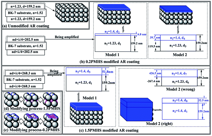
For 0.2PMHS modified AR coating, the central wavelength increased from 783 nm to 810 nm as the PMHS content increase from 0.00% to 1.50%. In Model 1 of 0.2PMHS modified AR coating, the physical thickness for B&W layer (d1) is equal to that of unmodified AR coating, which is 159.2 nm. Submitting n1 = 1.23 and n2 = 1.40 into the following equation:
| n1d1 + n2d2 = 810/4 nm | (4) |
We get the physical thickness of the blue layer (d2 = 4.8 nm).
In Model 2 of 0.2PMHS modified AR coating, the total physical thickness and optical thickness is 159.2 nm and 202.5 nm (λ0/4). So, there are two equations as following.
| d3 + d4 = 159.2 nm | (5) |
| n1d2 + n2d4 = 810/4 nm | (6) |
From the above two equations, we get the physical thickness of the B&W layer and blue layer (d3 = 119.5 nm, d4 = 39.7 nm).
For 1.5PMHS modified AR coating, the central wavelength increased from 783 nm to 1073 nm as the PMHS content increase from 0.00% to 1.50%. In Model 1 of 1.5PMHS modified AR coating, the physical thickness for B&W layer (d1) is also equal to that of unmodified AR coating, which is 159.2 nm.
Submitting n1 = 1.23 and n2 = 1.40 into the following equation:
| n1d1 + n2d5 = 1073/4 nm | (7) |
We get the physical thickness of the blue layer (d5 = 51.8 nm).
In Model 2 of 1.5PMHS modified AR coating, the total physical thickness and optical thickness is 159.2 nm and 268.3 nm (λ0/4). So, there are two equations as following.
| d6 + d7 = 159.2 nm | (8) |
| n1d6 + n2d7 = 1073/4 nm | (9) |
We get the physical thickness of the B&W layer and blue layer from eqn (8) and (9) (d6 = −267.4 nm, d7 = 426.5 nm). The value of film thickness of B&W layer is negative, which indicate that the Model 2 for 1.5PMHS modified AR coating is wrong. The other possibility for Model 2 is that all of pores in AR coating were filled with PMHS chains and there is an additional coating formed on the surface as shown in Fig. 4(c). So, the refractive index of the whole modified AR coating is 1.40, and there are eqn (10) for the right Model 2.
| n2(d1 + d8) = 1073/4 nm | (10) |
From eqn (9), we get the physical thickness of the whole AR coating ((d1 + d8) = 191.6 nm).
Finally, the refractive index and physical thickness of Model 1 and Model 2 for 0.2PMHS and 1.5PMHS modified AR coatings were calculated and the results were shown in Fig. 4. By inputting the refractive index and physical thickness of these four simulated AR coating into the TFCalc™ software, the theoretical transmittance spectra of them were obtained and compared with the experimental transmittance spectra of 0.2PMHS and 1.5PMHS modified AR coatings. As shown in Fig. 5(a), for 0.2PMHS modified AR coating, the experimental transmittance spectrum is in accordance with modeled transmittance spectrum of Model 1; and according to the Fig. 5(b), for 1.5PMHS modified AR coating, the experimental transmittance spectrum is more similar to the modeled transmittance spectrum of Model 2. These indicate that, during modifying process, the 0.2PMHS chains tend to aggregate onto the surface of AR coating while the 1.5PMHS chains prefer to penetrate into the pores of AR coating. This is in good accordance with the above discussion.
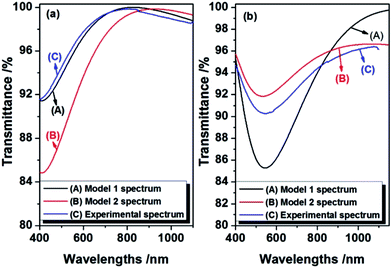 | ||
| Fig. 5 Experimental and theoretical transmittance spectra of 0.2PMHS (a) and 1.5PMHS (b) modified AR coatings. | ||
The SEM images combined with the simulation results demonstrate that the microstructure and hence the optical property of sol–gel silica AR coating can be controlled by using PMHS with different chain length. For the sol–gel silica AR coating used in high power laser system, 0.2PMHS is a good modifier.
3.3 Hydrophobicity and AR stability
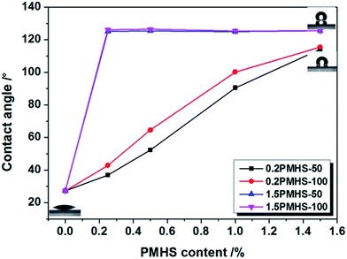
Another important property of AR coating is the hydrophobicity. With increasing hydrophobicity, the AR stability can be significantly improved.42 The aim of this work is to improve the hydrophobicity of silica AR coating by PMHS surface modification and hence to improve its AR stability. The hydrophobicity can be represented by the water contact angle.43,44 As shown in Fig. 6, the water contact angle of unmodified silica AR coatings is only 27.2°, which indicating that it is hydrophilic. For 0.2PMHS modified AR coating, the water contact angle increased gradually with PMHS content. As the 0.2PMHS content in modifier solution increases from 0.00% to 1.50%, the water contact angle of 0.2PMHS modified AR coating increases from 27.2° to about 115°. Surprisingly, as the PMHS content in modifier solution increases only from 0.00% to 0.25%, the water contact angle of 1.5PMHS modified AR coatings increases immediately from 27.2° to about 125°; and as the PMHS content continue to increase from 0.25% to 1.50%, the water contact angle of 1.5PMHS modified AR coatings is almost the same. The general formula of PMHS is shown in Fig. 2(a). 1.5PMHS is the concentrated hydrogen silicone oil, in which there is no –Si(CH3)2O– unit. Therefore, during PMHS surface modification process, 1.5PMHS would remove more –Si–OH groups on the surface of silica particles. However, for 0.2PMHS, in addition to the –SiCH3(H)–O– units, there are also about 140 –Si(CH3)2O– units. These –Si(CH3)2O– units would not only reduce the density of –Si–H groups but also shield the –Si–OH on the surface of AR coating and slow down the reaction rate of PMHS and –Si–OH. So, as the AR coating were dipped into the modifier solution with very low 0.2PMHS content and drawing immediately, there are still many –Si–OH on the surface of silica AR coating. The increasing content of 0.2PMHS is benefit for surface hydrophobic modification.In summary, the 1.5PMHS modified AR coatings possess a little bit better hydrophobicity than 0.2PMHS modified AR coating. However, after taking transmittance into account, 0.2PMHS is still the best candidate for surface hydrophobic modification of sol–gel silica AR coating. As the PMHS content in modifier solution is 1.50% and the withdraw rate is 100 mm min−1, the water contact angle of 0.2PMHS modified AR coating is 115.5° while its transmittance is 99.9%.
AR stability of pure and 0.2PMHS modified silica AR coatings were tested by keeping them in a closed container with 95% relative humidity at room temperature for 1 month. Fig. 7 shows the maximum transmittance of pure and 0.2PMHS modified silica AR coatings before and after one-month test. The maximum transmittance of pure silica AR coating decreases from 100.0% to 98.4%, while that of 0.2PMHS modified silica AR coating decreases from 99.9% to 99.5%. This indicates that the AR stability of sol–gel silica AR coating is obviously improved after PMHS surface modification. This is attributed to the introduction of amounts of hydrophobic methyl groups into the sol–gel silica AR coating.
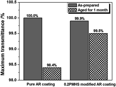 | ||
| Fig. 7 Change in maximum transmittance of pure and 0.2PMHS modified AR coating before and after one-month test. | ||
3.4 Surface morphology
PMHS surface modification may change the surface morphology of silica AR coating. It has been demonstrated that 0.2PMHS is the best modifier for sol–gel silica AR coatings. Therefore, the surface morphologies of AR coatings modified by 0.2PMHS solutions with PMHS content of 0.00%, 0.50%, 1.00% and 1.50% were analyzed by atomic force microscopy (AFM). Fig. 8 shows that the 0.2PMHS surface modification of AR coating did not significantly affect the surface morphologies. As the PMHS content increased from 0.00% to 1.50%, the room-mean-square (RMS) roughness (Rq) decreased slightly from 6.95 nm to 5.76 nm. This indicated that the PMHS surface modification did not obviously affect the roughness of sol–gel silica AR coatings. The low roughness would prevent the AR coatings from suffering light scattering.32 In addition, the adhesion forces between probe of AFM and 0.2PMHS modified AR coatings were also recorded by AFM. The adhesion forces decrease from 2.21 nN to 0.98 nN as the PMHS content increases from 0.00% to 1.50%. This is in very good agreement with the results from water contact angles. By increasing the PMHS content from 0.00% to 1.50%, the water contact angle of 0.2PMHS modified AR coating with 100 mm min−1 withdraw rate increased from 27.2° to 115.5°.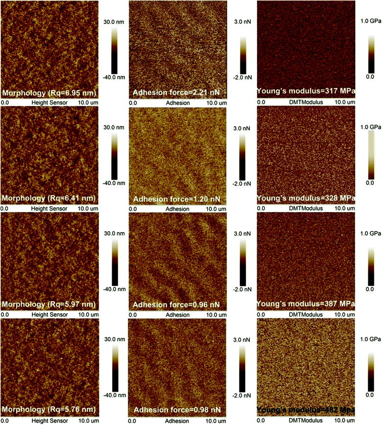 | ||
| Fig. 8 Effect of PMHS content on the surface morphology, adhesion forces and Young's modulus and of 0.2PMHS modified AR coatings. | ||
The unmodified AR coating is hydrophilic, and therefore the adhesion force between the hydrophilic coating and silicon tip is large. With the increasing PMHS content, the surface of silica AR coating become more and more hydrophobic, and therefore the adhesion forces between the hydrophobic coating and silicon tip is smaller.
3.5 Mechanical property
The silica particles in base-catalyzed sol–gel silica AR coatings are kept contact only by point contact forces, and the binding forces within the coatings are therefore quite weak.30 This results in the poor mechanical property of base-catalyzed sol–gel silica AR coatings.37,38 As shown in Fig. 8, the Young's modulus of unmodified AR coating is 317 MPa. After being immerging in the modifier solutions with increasing PMHS solution, the Young's modulus of AR coating increases from 317 MPa to 482 MPa, which indicates that the 0.2PMHS surface modification improves obviously the mechanical property of AR coating. This is also in good agreement with modifying process of 0.2PMHS modified AR coating as shown in Fig. 2(c). After 0.2PMHS surface modification, the individual particles of AR coating were covalently bonded together, and hence the mechanical property was improved.4. Conclusions
Hydrophobic sol–gel silica AR coatings with excellent transmittance and improved mechanical property and AR stability were prepared by a PMHS (poly(methylhydrogen)siloxane) surface modification. The speculation and verification of PMHS surface modification of sol–gel silica AR coating was discussed in detail. This explains well the effect of PMHS modification on the microstructure, optical properties, hydrophobicity and mechanical property. PMHS surface modification significantly improves the hydrophobicity, mechanical property while still remaining excellent transmittance of 99.9%. This PMHS surface modification will find important application in high power laser system.Acknowledgements
The authors gratefully acknowledge the support from Natural Science Foundation of Fujian Province (2015J05092), National Natural Science Foundation of China (61505029 and 61405180).References
- R. E. Nowak, M. Wehse, O. Sergeev, T. Voss, M. Seyfried, K. von Maydell and C. Agert, Adv. Opt. Mater., 2014, 2, 94 CrossRef.
- L. Yao and J. He, Prog. Mater. Sci., 2013, 61, 94 CrossRef.
- E. I. Moses, Energy Convers. Manage., 2008, 49, 1795 CrossRef CAS.
- Y. Lee, W. Ho and C. Yeh, Appl. Surf. Sci., 2015, 354, 20 CrossRef CAS.
- L. Yan, H. Lv, C. Wang and X. Yuan, Opt. Laser Technol., 2011, 43, 232 CrossRef CAS.
- J. Q. Xi, M. F. Schubert, J. K. Kim, E. F. Schuber, M. Chen, S. Y. Lin, W. Liu and J. A. Smart, Nat. Photonics, 2007, 1, 176 CAS.
- L. Xiao, Y. Lv, W. Dong, N. Zhang and X. Liu, ACS Appl. Mater. Interfaces, 2016, 8, 27107 CAS.
- S. Walheim, E. Schäffer, J. Mlynek and U. Steiner, Science, 1999, 283, 520 CrossRef CAS PubMed.
- M. Ibn-Elhaj and M. Schadt, Nature, 2001, 410, 796 CrossRef CAS PubMed.
- X. Li, L. Xue and Y. Han, J. Mater. Chem., 2011, 21, 5817 RSC.
- J. Szczyrbowski, G. Bräeuer, M. Ruske, G. Teschner and A. Zmelty, J. Non-Cryst. Solids, 1997, 218, 262 CrossRef CAS.
- J. Hiller, J. D. Mendelsohn and M. F. Rubner, Nat. Mater., 2002, 1, 59 CrossRef CAS PubMed.
- Y. Du, L. E. Luna, W. S. Tan, M. F. Rubner and R. E. Cohen, ACS Nano, 2010, 4, 4308 CrossRef CAS PubMed.
- C. Zhang, C. Zhang, J. Sun, R. Ding, Q. Zhang and X. Yao, RSC Adv., 2015, 5, 56998 RSC.
- P. A. Sermon, M. S. W. Vong, N. Bazin, R. Badheka and D. Spriggs, Proc. SPIE, 1995, 2633, 464 CrossRef CAS.
- F. Chi, G. Wei, Q. Zhang, X. Sun, L. Zhang, X. Lu, L. Wang, F. Yi and X. Gao, App. Surf. Sci., 2015, 356, 593 CrossRef CAS.
- X. Wang and J. Shen, J. Sol-Gel Sci. Technol., 2012, 61, 206 CrossRef CAS.
- S. Kim, A. Cho, S. Kim, W. Cho, M. H. Chung, S. Kim and J. H. Kim, RSC Adv., 2016, 6, 19280 RSC.
- X. Zhang, P. Lan, Y. Lu, J. Li, H. Xu, J. Zhang, Y. P. Lee, J. Y. Rhee, K. Choy and W. Song, ACS Appl. Mater. Interfaces, 2014, 6, 1415 CAS.
- N. Mizoshita, M. Ishii, N. Kato and H. Tanaka, ACS Appl. Mater. Interfaces, 2015, 7, 19424 CAS.
- I. M. Thomas, A. K. Burnham, J. R. Ertel and S. C. Frieders, Proc. SPIE, 1999, 3492, 220 CrossRef CAS.
- T. I. Suratwala, L. Hanna, E. L. Miller, P. K. Whitman, I. M. Thomas, P. R. Ehrmann, R. S. Maxwell and A. K. Burnham, J. Non-Cryst. Solids, 2003, 316, 349 CrossRef CAS.
- M. Manca, A. Cannavale, L. De marco, A. S. Aricò, R. Cingolani and G. Gigli, Langmuir, 2009, 25, 6357 CrossRef CAS PubMed.
- S. S. Latthe, H. Imai, V. Ganesan, C. Kappenstein and A. V. Rao, J. Sol-Gel Sci. Technol., 2010, 53, 208 CrossRef CAS.
- A. B. Gurav, S. S. Latthe, C. Kappenstein, S. K. Mukherjee, A. V. Rao and R. S. Vhatkar, J. Porous Mater., 2011, 18, 361 CrossRef CAS.
- S. Cai, Y. Zhang, H. Zhang, H. Yan, H. Lv and B. Jiang, ACS Appl. Mater. Interfaces, 2014, 6, 11470 CAS.
- L. Yao, Y. Zhu, D. Qu, M. Du, J. Shen and J. Wang, SPIE, in ICO20: Optical Design and Fabrication, International Society for Optics and Photonics, 2006, p. 60340V Search PubMed.
- Y. Zhang, D. Wu, Y. Sun and S. Peng, J. Sol-Gel Sci. Technol., 2005, 33, 19 CrossRef.
- Y. Akamatsu, K. Makita, H. Inaba and T. Minami, Thin Solid Films, 2001, 389, 138 CrossRef CAS.
- H. G. Floch and P. F. Belleville, J. Sol-Gel Sci. Technol., 1994, 1, 293 CrossRef CAS.
- L. Zhang, Y. Xu, D. Wu, Y. Sun, X. Jiang and X. Wei, Opt. Laser Technol., 2008, 40, 282 CrossRef CAS.
- I. M. Thomas, Proc. SPIE, 1992, 1848, 281 CrossRef CAS.
- X. Zhang, C. Cao, B. Xiao, L. Yan, Q. Zhang and B. Jiang, J. Sol-Gel Sci. Technol., 2010, 53, 79 CrossRef CAS.
- X. Zhang, B. Xia, H. Ye, Y. Zhang, B. Xiao, L. Yan, H. Lv and B. Jiang, J. Mater. Chem., 2012, 22, 13132 RSC.
- S. S. Prakash, C. J. Brinker, A. J. Hurd and S. M. Rao, Nature, 1995, 374, 439 CrossRef CAS.
- W. T. Wang, N. Lu, J. Y. Hao, H. B. Xu, D. P. Qi and L. F. Chi, J. Phys. Chem. C, 2010, 114, 1989 CAS.
- X. Zhang, B. Xia, B. Ding, Y. Zhang, J. Luo and B. Jiang, Mater. Lett., 2013, 104, 31033 Search PubMed.
- L. Xu, Z. Geng, J. He and G. Zhou, ACS Appl. Mater. Interfaces, 2014, 6, 9029 CAS.
- L. Xu and J. He, J. Mater. Chem. C, 2013, 1, 4655 RSC.
- F. Chi, L. Yan, H. Lv, C. Wang and X. Yuan, Thin Solid Films, 2011, 519, 2483–2487 CrossRef CAS.
- X. Zhang, W. Su, M. Lin, X. Miao, L. Ye, W. Yang and B. Jiang, J. Sol-Gel Sci. Technol., 2015, 74, 594 CrossRef CAS.
- S. Kim, J. Cho and K. Char, Langmuir, 2007, 23, 6737 CrossRef CAS PubMed.
- M. T. Nayakasinghe, A. Chakradhar, N. Sivapragasam and U. Burghaus, Appl. Surf. Sci., 2016, 364, 822 CrossRef CAS.
- S. Sarkar, S. K. Bhadra and S. Jana, RSC Adv., 2016, 6, 46048 RSC.
Footnotes |
| † Electronic supplementary information (ESI) available: Theoretical calculation of molecule weight and chain length of PMHS. See DOI: 10.1039/c7ra04400c |
| ‡ These authors contributed to this work equally. |
| This journal is © The Royal Society of Chemistry 2017 |

