 Open Access Article
Creative Commons Attribution 3.0 Unported Licence
Water-repellent and corrosion-resistance properties of superhydrophobic and lubricant-infused super slippery surfaces
Fan Songad,
Cuiqing Wuad,
Hailong Chen *b,
Qi Liu
 ac,
Jingyuan Liu
 ac,
Rongrong Chencd,
Rumin Liad and
Jun Wang
 ad
ad
aCollege of Material Science and Chemical Engineering, Harbin Engineering University, Harbin 150001, People's Republic of China
bCollege of Shipbuilding Engineering, Harbin Engineering University, Harbin 150001, Heilongjiang, P. R. China. E-mail: Chenhailong2017@163.com
cKey Laboratory of Superlight Material and Surface Technology, Ministry of Education, Harbin Engineering University, Harbin 150001, People's Republic of China
dInstitute of Advanced Marine Materials, Harbin Engineering University, Harbin 150001, People's Republic of China
First published on 14th September 2017
Abstract
Inspired by lotus leaves and pitcher plants, superhydrophobic surfaces and super slippery surfaces have been fabricated to improve the characteristics of AZ31 magnesium alloy surfaces. Here, a superhydrophobic surface with a hierarchical structure was constructed on a magnesium alloy surface via a one-step, environmentally friendly method, and a slippery liquid-infused porous surface (SLIPS) was obtained by immersing the superhydrophobic surface in perfluoropolyether. Compared with an untreated magnesium alloy and the prepared superhydrophobic coating, the SLIPS coating showed good corrosion resistance in 3.5 wt% NaCl solution according to electrochemical tests. The present study provides more possibilities to extend the application of special wettable surfaces.
1. Introduction
Magnesium (Mg) and its alloys are light materials and have been applied widely in automobile fields, biological materials, aerospace, aircraft, and household equipment.1–4 Mg also possesses several advantageous properties: high thermal conductivity, high dimensional stability, good electromagnetic screening, easy fabrication, and recyclability.5However, Mg alloys have some properties that hinder their extensive application: high chemical activity, easy oxidization, poor abrasion performance and poor corrosion resistance.6 It is crucial to confer Mg alloys with high corrosion resistance, and two main approaches have been applied to enhance the corrosion resistance of Mg alloys: using high purity alloys that retain heavy metal impurities below a threshold value; post-processing and surface modification processing.7–9 Surface modification of Mg alloys can be done using chemical conversion films,10 micro-arc oxidation,11 polymer films,12 layer-by-layer self-assembly,13 and layered double hydroxide (LDH) coating.14
Inspired by the unique properties of living beings, researchers have tried to simulate natural materials, especially special wetting interface materials that are superhydrophobic, superhydrophilic, superaerophobic or superaerophilic.15 Due to its liquid-repellent properties, superhydrophobic surfaces have prominent corrosion resistance as well as anti-fouling, anti-icing, friction-reduction, and oil/water-separation properties.16–20 Like the lotus leaf, the superhydrophobic surface has special wettability as the static contact angle for water is >150°.21–23 Studies have shown that water droplets on a solid surface can be classified into two states: Wenzel and Cassie–Baxter.24,25 Because of the roughness of the superhydrophobic surface, the Cassie–Baxter state is a better fit for the superhydrophobic surface.
The “air cushion” principle can protect a metal alloy from corrosion in a corrosive medium. Wang et al.26 proposed a novel one-step potentiostatic electrolysis method to fabricate superhydrophobic films on a copper surface. The superhydrophobic film presented excellent inhibition to copper corrosion and stability in water containing Cl−. Mo et al.27 fabricated a TiO2/fluoromethylhydro-silicone oil composite coating which possessed excellent anti-corrosion performance and exhibited superhydrophobicity. Xiao et al.28 fabricated a superhydrophobic surface via two steps. First, the copper surface was anodized in KOH solution to generate Cu(OH)2 nanoneedle arrays. Second, the surface was grafted with FAS to achieve superhydrophobicity. The superhydrophobicity was found to be stable at pH 1–13 but decreased substantially in 3.5 wt% NaCl solution due to the loss of the hierarchical microstructures in nanoneedle arrays. Although the superhydrophobic surface possesses a corrosion-resistant function, it cannot retain this function under a liquid environment for a long time.
Based on the above-reported faults, increasing numbers of researchers have proposed new types of repellent surfaces: slippery liquid-infused porous surfaces (SLIPS).29,30 Aizenberg and colleagues were the first to study SLIPS, which were inspired by a pitcher plant.31 The entrapped lubricant is immiscible to the water phase and other liquids, so it is not destroyed and the lubricant is stored for a long time.32 In this way, the SLIPS can overcome corrosion resistance under a poor environment for a long time.33 However, most reports had ignored the oil retention of SLIPS and whether the structure of the surface can influence the properties of the super slippery surface. The differences in the results between superhydrophobic surfaces and SLIPS have rarely been studied.
In the present study, we fabricated a superhydrophobic surface on an AZ31 Mg alloy via a single one-step hydrothermal method.34 Then, SLIPS were created by infusing perfluoropolyether (PFPE) onto the superhydrophobic surfaces. A bare Mg alloy was also infused with PFPE to compare it with the SLIPS in terms of corrosion resistance. In addition, the corrosion behaviour of the superhydrophobic surface and SLIPS were studied after different immersion times. The proposed superhydrophobic surfaces may have a considerable effect on the corrosion resistance of metals.
2. Experimental section
2.1 Materials and reagents
AZ31 Mg alloy was used as the substrate. Its chemical composition was Mg (2.98 wt%), Al (0.88 wt%), Zn (0.38 wt%), Mn (0.0135 wt%), Si (0.0027 wt%), Fe (0.002 wt%) and Ni (0.001 wt%). The Mg alloy was cut into strips of size 30 mm × 30 mm × 2 mm. Stearic acid, manganese sulfate, PFPE and absolute ethanol were the primary reagents. All reagents were of analytical grade and used without further purification.2.2 Pre-treatment of Mg alloy
The AZ31 Mg alloy substrates were ground with silicon carbide papers (600#, 1000#, 2000#) to remove the oxide/hydroxide layer from their surfaces. Then, they were ultrasonically cleaned in acetone and absolute ethanol for 10 min to remove impurities, respectively. Finally, they were washed with deionized water and dried by a hair drier.2.3 Fabrication of superhydrophobic and slippery coatings
Equal volumes of 0.01 mol L−1 MnSO4 aqueous solution and a 0.01 mol L−1 ethanolic solution of stearic acid were mixed and stirred for 5 min. Then, the solution and a dried Mg alloy plate were placed in Teflon-lined autoclaves. The reaction kettle was heated to 140 °C and maintained at that temperature for 7 h. The autoclave was cooled naturally to room temperature and the specimen rinsed with deionized water and dried at 60 °C for 6 h. In this way, a superhydrophobic coating was obtained. The as-prepared superhydrophobic Mg alloy was immersed in PFPE for 4 h and placed horizontally for 6 h at room temperature to remove excess oil. Finally, the SLIPS was built on AZ31. To compare with the SLIPS, the bare AZ31 Mg alloy was immersed in PFPE for 4 h and placed horizontally for 6 h at room temperature as the comparison sample.2.4 Characterization
The static contact angles of the prepared coatings were measured by a FTA200 drop shape analysis system at room temperature to describe wettability. Morphological analysis was carried out using a scanning electron microscope (FEI Quanta 200FEG) equipped with an energy-dispersive spectrometer. The surface compositions were characterized by Fourier transform infrared (FTIR) spectroscopy using a spectrophotometer (100 series, PerkinElmer). The corrosion resistance of the Mg alloys with superhydrophobic surfaces and super slippery surfaces and bare sample were tested at room temperature using a conventional electrochemical workstation (Zennium; IM6) equipped with a three-electrode system: an Ag/AgCl reference electrode consisting of a saturated KCl solution, a platinum mesh as the counter electrode and the sample as the working electrode. The performance of the working electrode (1 cm2) was determined in 3.5 wt% NaCl aqueous solution. Electrochemical impedance spectroscopy (EIS) was conducted in the frequency range from 10 mHz to 100 kHz with a perturbation amplitude sinusoidal signal of 10 mV. All electrochemical tests were repeated at least thrice to ensure reproducibility and reliability.3. Results and discussion
3.1 Surface morphology and composition
In this report, the formation of superhydrophobic surfaces and super slippery surfaces on Mg alloy substrates is described. These were fabricated using a one-step hydrothermal method and immersion method, and the mechanism of formation is shown in Scheme 1. Scanning electron micrography (SEM) images at different magnifications of the as-prepared superhydrophobic surfaces are displayed in Fig. 1a–c, which show the micro-morphology of the surfaces. The superhydrophobic surface was built with a “micro flower” structure (Fig. 1a and b). The radius of the flower structure was ≈12 μm. The structure of the flower was very complex, and was formed by a needle with a diameter of 100 nm and 1 μm (Fig. 1c). We concluded that the structure of the superhydrophobic surface consisted of nano- and micro-robust hierarchical structures. It has been reported that a robust hierarchical structure is a key factor for a superhydrophobic surface.35,36 | ||
| Scheme 1 Preparation of the superhydrophobic film and super slippery surface on the AZ31 magnesium alloy (schematic). | ||
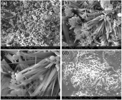 | ||
| Fig. 1 Scanning electron micrographs of the surface of the as-prepared superhydrophobic AZ31 at different magnifications (a–c) and the super slippery surface (d). | ||
Fig. 1d shows that the super slippery surface microstructure was different to the structure of the superhydrophobic surface. SEM shows that the super slippery surface became thickened, the original micro/nano-hierarchical structure was covered with lubricating oil, part of the gap was partially filled, and that injection of lubricating oil did not affect the flower-like composite structure of the whole surface.
The hierarchical micro/nano-scaled structure provided more space to capture the air to achieve superhydrophobicity and store lubricating oil to maintain this lubricating property.
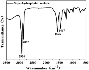
The chemical composition of the as-prepared superhydrophobic surface was measured by FTIR spectroscopy in the frequency range 3500–500 cm−1. Fig. 2 depicts the FTIR spectrum of the treated sample. The peaks at 2920 and 2857 cm−1 corresponded to the asymmetric and symmetric stretching vibrations of –CH2– groups, respectively, in the high-frequency region.37 In the low-frequency region, peaks at 1576 cm−1 and 1467 cm−1 appeared, which was not noted in the original stearic acid, and the carboxyl group (–COO) peak at ≈1701 cm−1 does not appear in Fig. 2. This observation suggested that carboxylate (CH3(CH2)16COO−) was formed on the substrate.
To confirm the infusion of lubricating oil onto the surface, electron-dispersive spectroscopy (EDS) was carried out. Fig. 3 shows the EDS spectra of the superhydrophobic surface (a) and SLIPS (b). The elements C, O, Mg, Mn and S were clearly detected on both sample surfaces. Compared with the superhydrophobic surface, a new element (F) and more C were observed in the SLIPS spectrum. The main component of the lubricating oil PFPE allowed effective irrigation into voids within the superhydrophobic surface.
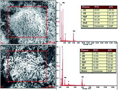 | ||
| Fig. 3 EDS of (a) the surface of the as-prepared superhydrophobic AZ31 and (b) super slippery surface. | ||
3.2 Analysis of the wettability of different samples
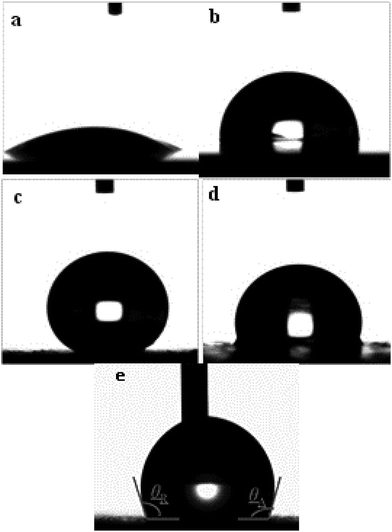
The wettability of the four types of surfaces was measured using the static contact angle (CA) of water. The CA on an identical surface was measured at five locations to obtain the average value. The corresponding CA images are summarized in Fig. 4. The CA of the water droplet on the bare AZ31 Mg alloy surface was ≈52° (Fig. 4a) and the CA of the slippery liquid-infused AZ31 Mg alloy was 90° (Fig. 4b). The CA of the as-prepared superhydrophobic surface was ≈155°, which was more than that attributed to the material with a special hierarchical structure and low surface energy (150°) (Fig. 4c). The CA of SLIPS was 105° (Fig. 4d). In addition, the dynamic wettability of SLIPS was measured, and the advancing CA and reducing CA were 106° and 103°, respectively (Fig. 4e). The small contact angle hysteresis (CAH) of ≈3° demonstrated that the droplet water could “roll off” from the surface. Typically, the water droplet on the superhydrophobic surface and super slippery surface maintained the Cassie state. The difference between the two types of surfaces was that the air layer trapped on the superhydrophobic surface was replaced by lubricating oil (PFPE). Based on the Cassie–Baxter equation:25cos![[thin space (1/6-em)]](https://www.rsc.org/images/entities/char_2009.gif) θ = fls θ = fls![[thin space (1/6-em)]](https://www.rsc.org/images/entities/char_2009.gif) cos cos![[thin space (1/6-em)]](https://www.rsc.org/images/entities/char_2009.gif) θ0 − flv θ0 − flv |
3.3 Stability of superhydrophobic and super slippery surfaces
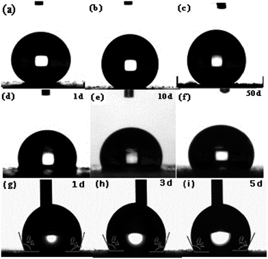 | ||
| Fig. 5 Static contact angle of superhydrophobic surfaces (a–c), super slippery surfaces (d–f) and dynamic wettability of the SLIPS after different times (g–i). | ||
To further investigate the long-term stability of the SLIPS, we tested the dynamic wettability. The video screenshots in Fig. 5g–i show the advancing (θA) CA and receding (θR) CA to be different. The θA and θR CAs were 106° and 103°, 110° and 106° and 110 ± 1° and 106° after air exposure for 1, 3 and 5 days, respectively. Using these results, the CAH was calculated to be 3°, 4°and 4°, respectively. It has been reported that CAH is due to a barrier at the front of the droplet.38 The smaller the CAH, the easier it is for the droplets to roll from the solid surface. We noted that the CAH changed only slightly, a result that was consistent with a static contact angle. From a long-term viewpoint, the super slippery surface could achieve self-repair by repeated infiltration of a lubricating oil surface for the purpose of sustainable recycling.
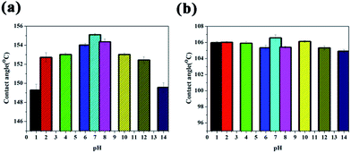 | ||
| Fig. 6 Change in contact angle of water droplets with pH values from 1 to 14 on a (a) superhydrophobic surface and (b) super slippery surface. | ||
The existence of the air layer can be explained by the photographs of the treated surfaces immersed in water (Fig. 7). The submerged region of the superhydrophobic sample looked like a silver mirror when viewed from an oblique angle, which indicated that the air cushion had been trapped on the micro/nanostructure based on the total reflection theory.39 The SLIPS Mg alloy showed no change on the surface irrespective of whether the area was immersed in water or exposed to air. These results further confirmed the notion that air pockets were replaced by lubricating oil (PFPE), which was in good agreement with the SEM image (Fig. 1d).
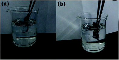 | ||
| Fig. 7 (a) Superhydrophobic film sample and (b) super slippery surface specimen immersed in deionized water at a certain slant angle. | ||
Overall, the superhydrophobic surface and super slippery surface had long-term stability and chemical stability, which can meet the requirements of applications. Indeed, the SLIPS applications are more extensive than those for compounds with a superhydrophobic coating.
3.4 Corrosion resistance of superhydrophobic and super slippery surfaces
The corrosion inhibition of the samples was investigated by potentiodynamic polarization between −0.4 V and 1.6 V in a traditional 3.5 wt% NaCl solution. Fig. 8 shows the polarization curves of the bare, superhydrophobic and super slippery surfaces, and the electrochemical parameters are summarized in Table 1. The current densities (icorr) of treated samples (superhydrophobic surface and super slippery surface) decreased by more than three and five orders of magnitude in comparison with that of the bare AZ31 specimen, respectively (Fig. 8). Moreover, the icorr of the SLIPS was two orders of magnitude lower than that of the superhydrophobic coating. Interestingly, there was no obvious cathode and anode current, and it was nearly a straight line (10−9 A cm−2), indicating better corrosion resistance after SLIPS formed on the surface of the Mg alloy. The main reason for this result was that high scanning potentials can damage the super slippery surface, so measurement of the potential polarization is not an appropriate method to evaluate the surface.38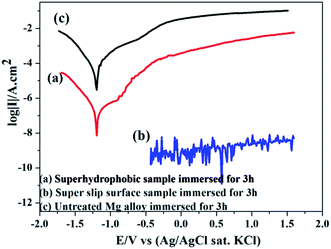 | ||
| Fig. 8 Polarization curves of untreated AZ31, superhydrophobic AZ31 and SLIPS AZ31 in 3.5 wt% NaCl aqueous solution. | ||
| Sample | Time (h) | Ecorr (V/(Ag/AgCl)) | icorr (μA cm−2) |
|---|---|---|---|
| Bare Mg | 3 | −1.195 | 15.8 |
| Superhydrophobic Mg | 3 | −1.176 | 0.219 |
To investigate the corrosion resistance of the samples further, the corrosion behavior of different types of surfaces was studied by EIS in 3.5 wt% NaCl aqueous solution.
Fig. 9 displays the Nyquist diagrams of the bare AZ31 Mg alloy, slippery liquid-infused Mg alloy, the superhydrophobic surface, and the SLIPS immersed in 3.5 wt% NaCl aqueous solution for 6 h, respectively. The diameter of the Nyquist plots of the SLIPS was the largest and had only a capacitive loop in the high-frequency region (Fig. 9a). Many studies have shown that the larger the diameter of Nyquist plots, the lower is the corrosion rate and the better is the corrosion resistance, and that the capacitive loop is related to the charge transfer.40 In addition, there was no diffusion process, which indicated the electrochemical reaction on the SLIPS was only controlled by charge transfer. Thus, among these four types of surfaces, the SLIPS could decrease the corrosion rate the most. Fig. 9b shows that there were two capacitive loops in the high- and low-frequency ranges in the Nyquist plots for the superhydrophobic surface. The diameter of the capacitive loop in the Nyquist plots of the superhydrophobic Mg alloys was larger than that of the bare Mg alloy, suggesting that the superhydrophobic surface could decrease the corrosion rate. The enlarged Nyquist plots of the bare Mg alloy and slippery liquid-infused Mg alloy are shown in Fig. 9c; the diameters of these two surfaces were similar, which consisted of a medium-frequency capacitive loop and a low-frequency inductive loop. The latter demonstrated that the electrolyte was immersed in the surface, and that pitting corrosion occurred on the Mg alloy surface and the corrosive products deposited on the surface.41 In this way, we showed that the Mg alloy could not be protected from corrosion by infusing oil without a rough structure being present.
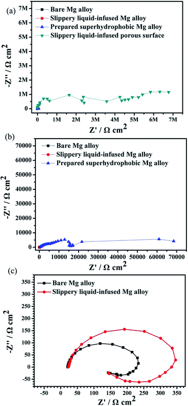 | ||
| Fig. 9 Nyquist plots for four types of surfaces immersed in 3.5 wt% NaCl aqueous solution for 6 h (a–c). | ||
The Bode diagrams were also measured. The low-frequency impedance modulus |Z| value represents the corrosion resistance of the surface. Fig. 10a shows that the impedance values of the bare AZ31 and slippery liquid-infused Mg alloy were similar and much lower than that of the as-prepared superhydrophobic surface and SLIPS. This observation indicates that the corrosion resistance of the bare AZ31 Mg alloy was improved by surface treatment of the superhydrophobic surface and SLIPS. The value of |Z|0.01 Hz decreased from ≈200 Ω cm2 for the untreated AZ31 Mg alloy to 105 Ω cm2 for the superhydrophobic coating after immersion for 6 h. Thus, the |Z| increased by three orders of magnitude. The value of |Z|0.01 Hz of SLIPS was 107 Ω cm2, which was increased by two orders in comparison with the superhydrophobic surface. Similar to other reports,42–44 the values of |Z| in the high-frequency range were evidently different between these four samples. The high-frequency limit of the Bode plots is supposed to represent the electrolyte resistance; the variation at 105 Hz was due to the air layer between the superhydrophobic interface and the solution, which made the electrolyte resistance for the superhydrophobic-coated Mg alloy larger than that for the untreated alloy. Moreover, the variation at 105 Hz was due to the oil layer between the super slippery interface and the solution, which made the electrolyte resistance for the SLIPS larger than for the other alloy samples. Fig. 10b (Bode plots of phase angle vs. frequency) shows one time constant at ≈0.1 Hz and another time constant at ≈100 Hz for the untreated AZ31 Mg alloy. The medium-frequency and low-frequency time constants could be ascribed to the electrolyte solution of the immersed bare Mg alloy surface and charge transfer-controlled process, respectively. The Bode plot of the superhydrophobic-treated sample and super slippery surface-treated sample showed two time constants at ≈10 Hz and ≈1000 Hz, respectively, which was ascribed to the self-capacitance and controlled charge transfer that occurred at the interface between the surfaces and substrates. In addition, the phase angle for the SLIPS and superhydrophobic surface at high and low frequency was higher than that of the bare and slippery liquid-infused Mg alloy, and the shape was distinct. The results stated above were in good agreement with the features of Nyquist plots observed in Fig. 10a.
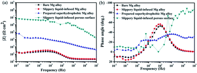 | ||
| Fig. 10 Bode plots for four types of surfaces immersed in 3.5 wt% NaCl aqueous solution for 6 h (a) |z| versus frequency, (b) phase angle versus frequency. | ||
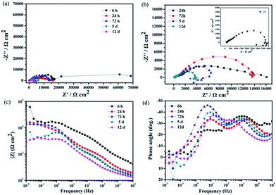
To understand the long-time stability of the superhydrophobic film and SLIPS, EIS tests were conducted after immersion in 3.5 wt% NaCl aqueous solution for different times at room temperature. The results of the superhydrophobic surface and super slippery surface were observed from Nyquist plots and Bode plots in Fig. 11 and 12. The diameters of the capacitive loops of the Nyquist plots and values of |Z|0.01 Hz decreased gradually with increasing immersion time (Fig. 11) due to the decreased thickness of the air layer between the superhydrophobic surface and NaCl solution. The Nyquist plots for superhydrophobic samples immersed for >5 days contained a high-frequency capacitive loop, a medium-frequency capacitive loop, and a low-frequency inductive loop (Fig. 11b). Bode plots of phase angle vs. frequency (Fig. 11 days) showed that there were two time constants for the superhydrophobic surface immersed for <72 h and three time constants for the surface immersed for 5 days to 12 days. The phase angles of the superhydrophobic sample immersed for 5 days to 12 days were <0° in the low-frequency range, indicating pitting corrosion on the surface. However, the charge transfer of the treated surface after immersion in NaCl solution for 12 days remained higher than that of the untreated sample, and the low-frequency modulus remained high. This effect was attributed to the water-repellence that prevented contact between the corrosion liquid and the substrate surface that resulted in corrosion resistance. These results indicated that the superhydrophobic surface could improve the corrosion resistance of the Mg alloy based on a robust micro/nanostructure trapping more air between the corrosion liquid and substrate.
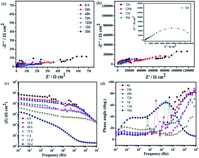
Fig. 12 shows the impedance plots of the SLIPS immersed in 3.5 wt% NaCl aqueous solution at different times. Although the diameters of the Nyquist diagrams and values of |Z|0.01 Hz decreased with increasing immersion time, the speed of decrease was relatively slow and steady. The value of |Z|0.01 Hz of the SLIPS immersed for 30 days remained >105 Ω cm2. The enlarged Nyquist plot (Fig. 12b) showed no inductive loop in the low-frequency range, which meant no pitting corrosion on the SLIPS Mg alloy after immersion for 30 days and the modulus value |Z| remained higher than that of the uncoated and superhydrophobic surface substrates after immersion for 30 days. These results further demonstrated that the liquid lubricants completely covered the surface and prevented surface electron transfer. Based on the results of the characterizations, we showed that the SLIPS possessed good long-term performance and corrosion resistance.
4. Conclusions
We prepared a hierarchical-structure superhydrophobic coating by a one-step hydrothermal method. Then, the SLIPS was formed by infusing PFPE into the superhydrophobic surface. The special micro/nanostructure made the surface more robust and crude to provide more space to store the air and oil in it, which helped to isolate the liquid from the Mg alloy substrate. Through CA tests, the SLIPS possessed better long-term durability than the superhydrophobic surface and bare substrate, which enhanced the possibilities for wide range of application. According to the results of electrochemical tests, the SLIPS possessed better corrosion resistance. The superhydrophobic coating and super slippery coating could meet the wide requirements of protecting Mg alloys from corrosion to a certain extent.Conflicts of interest
There are no conflicts to declare.Acknowledgements
This work was supported by National Natural Science Foundation of China (NSFC 51301050), Fundamental Research Funds of the Central University (HEUCFZ), Natural Science Foundation of Heilongjiang Province (B2015021), International Science & Technology Cooperation Program of China (2015DFA50050) and the Major Project of Science and Technology of Heilongjiang Province (GA14A101).References
- N. Wang, D. S. Xiong, Y. L. Deng, Y. Shi and K. Wang, ACS Appl. Mater. Interfaces, 2015, 7, 6260–6272 CAS.
- B. N. Sahoo, S. Nanda, J. A. Kozinski and S. K. Mitra, RSC Adv., 2017, 25, 15027–15040 RSC.
- Y. Wu, T. Hang and Z. Yu, Chem. Commun., 2014, 50, 8405–8407 RSC.
- D. D. Lv, H. F. Shao, X. Gao, K. Lu, H. F. Lu and H. Y. Ma, RSC Adv., 2016, 6, 93419–93427 RSC.
- K. Liu and L. Jiang, Nanoscale, 2011, 3, 825–838 RSC.
- P. Guo, M. Wen, L. Wang and Y. Zhang, Nanoscale, 2014, 6, 3917–3920 RSC.
- S. Jung, M. Dorrestijn, D. Raps, A. Das, C. M. Megaridis and D. Poulikakos, Langmuir, 2011, 27, 3059–3066 CrossRef CAS PubMed.
- L. Zhang, C. H. Xue, M. Cao, M. M. Zhang, M. Li and J. Z. Ma, Chem. Eng. J., 2017, 320, 244–252 CrossRef CAS.
- F. Zhang, S. Chen, L. Dong, Y. Lei, T. Liu and Y. Yin, Appl. Surf. Sci., 2011, 257, 2587–2591 CrossRef CAS.
- I. Milošev, T. Kosec and M. Bele, J. Appl. Electrochem., 2010, 40, 1317–1323 CrossRef.
- P. Wang, D. Zhang, R. Qiu, Y. Wan and J. Wu, Corros. Sci., 2014, 80, 366–373 CrossRef CAS.
- Z. Li, X. Z. Tang, W. Y. Zhu, B. C. Thompson, M. Y. Huang, J. L. Yang, X. Hu and K. A. Khor, ACS Appl. Mater. Interfaces, 2016, 8, 10985–10994 CAS.
- N. Gao, Y. Y. Yan, X. Y. Chen and D. J. Mee, Mater. Lett., 2011, 65, 2902–2905 CrossRef CAS.
- W. Geng, A. Hu and M. Li, Appl. Surf. Sci., 2012, 263, 812–824 CrossRef.
- E. C. Cho, J. Chang, W. Cai, H. C. Chen, K. S. Chuang, J. H. Zheng, Y. S. Hsio, K. C. Lee and J. H. Huang, Chem. Eng. J., 2017, 314, 347–357 CrossRef CAS.
- M. Ferrari and A. Benedetti, J. Colloid Interface Sci., 2015, 222, 291–304 CrossRef CAS PubMed.
- L. H. Kong, X. H. Chen, L. G. Yu, Z. S. Wu and P. Y. Zhang, ACS Appl. Mater. Interfaces, 2015, 7, 2616–2625 CAS.
- H. Y. Wang, Y. H. Wei, M. M. Liang, L. F. Hou, Y. G. Li and C. L. Guo, Colloids Surf., A, 2016, 509, 351–358 CrossRef CAS.
- M. U. M. Junaidi, N. N. R. Ahmad, C. P. Leo and H. M. Yee, Prog. Org. Coat., 2016, 99, 140–146 CrossRef CAS.
- M. J. Cheng, S. S. Zhang, H. Y. Dong, S. H. Han, H. Wei and F. Shi, ACS Appl. Mater. Interfaces, 2015, 7, 4275–4282 CAS.
- L. Feng, S. H. Li, Y. S. Li, H. J. Li, L. J. Zhang, Z. Jing, Y. L. Song, B. Q. Liu, L. Jiang and D. B. Zhu, Adv. Mater., 2002, 14, 1857–1860 CrossRef CAS.
- L. B. Feng, M. Yang, X. T. Shi, Y. H. Liu, Y. P. Wang and X. H. Qiang, Colloids Surf., A, 2016, 508, 39–47 CrossRef CAS.
- P. Zhang and F. Y. Lv, Energy, 2015, 82, 1068–1087 CrossRef.
- R. N. Wenzel, Ind. Eng. Chem. Res., 1936, 28, 988–994 CrossRef CAS.
- A. B. D. Cassie and S. Baxter, Trans. Faraday Soc., 1944, 40, 546–551 RSC.
- P. Wang, R. Qiu, D. Zhang, Z. F. Lin and B. R. Hou, Electrochim. Acta, 2010, 56, 517–522 CrossRef CAS.
- C. Y. Mo, Y. S. Zheng, F. L. Wang and Q. Mo, Int. J. Electrochem. Sci., 2015, 10, 7380–7391 CAS.
- F. Xiao, S. Yuan, B. Liang, G. Li, S. O. Pehkonen and T. Zhang, J. Mater. Chem. A, 2015, 3, 4378–4388 Search PubMed.
- N. Wang, D. S. Xiong, S. Pai, Y. L. Deng and Y. Shi, Appl. Surf. Sci., 2016, 387, 1219–1224 CrossRef CAS.
- P. Wang, D. Zhang and Z. Lu, Colloids Surf., B, 2015, 136, 240–247 CrossRef CAS PubMed.
- T. S. Wong, S. H. Kang, S. K. Y. Tang, E. J. Smythe, B. D. Hatton, A. Grinthal and J. Aizenberg, Nature, 2011, 477, 443–447 CrossRef CAS PubMed.
- S. S. Yang, R. Qiu, H. Q. Song, P. Wang, Z. Q. Shi and Y. F. Wang, Appl. Surf. Sci., 2015, 328, 491–500 CrossRef CAS.
- T. T. Song, Q. Liu, J. Y. Liu, W. L. Yang, R. R. Chen, X. Y. Jing, K. Takahashi and J. Wang, Appl. Surf. Sci., 2015, 355, 495–501 CrossRef CAS.
- N. Wei, Y. Y. Jiang, Y. Ying, X. Y. Guo, Y. P. Wu, Y. Wen and H. F. Yang, RSC Adv., 2017, 7, 11528–11536 RSC.
- H. J. Wang, J. Yu, Y. Z. Wu, W. J. Shao and X. L. Xu, J. Mater. Chem. A, 2014, 2, 5010–5017 CAS.
- L. P. Wen, Y. Tian and L. Jiang, Angew. Chem., Int. Ed., 2015, 54, 3387–3399 CrossRef CAS PubMed.
- N. Xu, D. K. Sarkar, X. G. Chen and W. P. Tong, Surf. Coat. Technol., 2016, 302, 173–184 CrossRef CAS.
- Z. K. Meng, Q. Wang, X. Z. Qu, C. L. Zhang, J. L. Li, J. G. Liu and Z. Z. Yang, Polymer, 2011, 52, 597 CrossRef CAS.
- J. L. Zhang, C. D. Gu and J. P. Tu, ACS Appl. Mater. Interfaces, 2017, 9, 11247–11257 CAS.
- C. Q. Wu, Q. Liu, R. R. Chen, J. Y. Liu, H. S. Zhang, R. M. Li, K. Takahashi, P. L. Liu and J. Wang, ACS Appl. Mater. Interfaces, 2017, 9, 11106–11115 CAS.
- G. Wang, Z. X. Zeng, J. J. Chen, M. Y. Xu, J. F. Zhu, S. Liu and T. H. Ren, RSC Adv., 2016, 5, 40641–40649 RSC.
- L. Ejenstam, A. Swerin, J. S. Pan and P. M. Claesson, Corros. Sci., 2015, 99, 89–97 CrossRef CAS.
- S. L. Zheng, C. Li, Q. T. Fu, T. F. Xiang, W. Hu, J. Wang, S. B. Ding, P. J. Liu and Z. Chen, RSC Adv., 2016, 6, 79389–79400 RSC.
- L. K. Wu, X. F. Zhang and J. M. Hu, Corros. Sci., 2014, 85, 482–487 CrossRef CAS.
| This journal is © The Royal Society of Chemistry 2017 |

