 Open Access Article
Creative Commons Attribution 3.0 Unported Licence
First-principles investigation of a β-MnO2 and graphene composite as a promising cathode material for rechargeable Li-ion batteries
Renhui Zhang *a,
Juan Zhaoa,
Lei Guo
 a,
Hangdao Qina,
Wei Shia and
Zhibin Lub
aResearch Center of Material and Chemical Engineering, School of Material and Chemical Engineering, Tongren University, Tongren, 554300, P. R. China. E-mail: zrh_111@126.com
bLanzhou Institute of Chemical Physics, Lanzhou 730000, P. R. China
First published on 9th June 2017
Abstract
In this investigation, we studied the effect of the synergistic mechanism on the stability and the electronic and Li diffusion performance of a β-MnO2 and graphene composite. The C–O covalent bonds formed in the stable interface not only improved the hybrid structure stability (a stable C–O bond forms between the β-MnO2 (110) plane and graphene) but also led to enhanced conductivity. The calculated results implied that a possible diffusion pathway with the lowest energy barrier was found along the hybrid structure interface.
1 Introduction
Manganese dioxide (MnO2) was the most promising material for low cost and environment-friendly battery systems for over a decade.1–3 Recently, it has received more attention in the field of supercapacitors.4–11 Several MnO2 polymorphs have been studied for use in Li-ion batteries, such as α-MnO2, β-MnO2 and γ-MnO2 (a mixture of α and β).12 Among them, due to the rutile structure of β-MnO2, which contains common phases of oxides (such as TiO2), much attention has been paid to β-MnO2. Mesoporous β-MnO2 exhibited high Li uptake.13 Furthermore, β-MnO2, which could be easily fabricated by the pyrolysis of MnOOH and a hydrothermal reaction, was thermodynamically stable.14,15 According to the literature, researchers have not paid more attention to crystallized β-MnO2 due to its poor ion insertion performance.16,17 To our excitement, the nano-composite and mesoporous β-MnO2 could further enhance the capacity of the Li ions, and the capacity could achieve values of 320 mA h g−1.18–20 This implied that the compact tunnel structure of β-MnO2 was conducive to accommodating the volume changes as well as charging and discharging.Graphene has attracted more attention as electrically conducive reinforced composites, sensors, and electrodes due to its superior chemical and physical properties.21 In particular, graphene has been treated as a potential electrode to recharge lithium ions due to its superior conductivity (electron mobility of 2 × 106 cm2 V−1 s−1) and large surface area (2630 m2 g−1).22–25 Cao et al. found that the sandwich-type functionalized graphene sheet-sulfur nanocomposite tested as a cathode in lithium-sulfur batteries exhibited a high reversible capacity of about 960 mA h g−1.26
To our knowledge, β-MnO2/graphene composite as a promising cathode electrode and graphene as an anode electrode were expected to obtain high voltages, high energies, and high power densities in neutral aqueous electrolytes.27–30 Wu et al. found that a MnO2 nanowire/graphene and graphene asymmetric electrochemical capacitor could be cycled reversibly in a high-voltage region of 0–2.0 V and showed an excellent energy density of 30.4 W h kg−1 and a high power density of 5000 W kg−1 at 7.0 W h kg−1.30
But above all, not only graphene but also MnO2 could have an important role as electrode materials to obtain a synergetic effect, leading to excellent cyclic properties and eventually higher reversible capacities.31,32 However, previous work focused on experimental studies with MnO2 and graphene as the cathode electrode of a lithium battery. The synergistic mechanism of MnO2 and graphene and the intercalation or deintercalation of Li are still not well understood, and they are seldom systematically reported in theoretical studies. Additionally, the charge–discharge process is complex, and it is still rather difficult to directly characterize Li diffusion at the atomic level.33 Therefore, the first-principles method was selected in this work in order to analyze the properties and mechanism of Li adsorption on MnO2 and a graphene hybrid structure (a stable C–O bond forms between the β-MnO2 (110) plane and graphene). We investigate the structural stability and the electronic and Li diffusion properties of the MnO2 and graphene hybrid structure.
2 Method and model
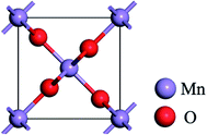
The DFT calculations were performed with CASTEP code,34 using the generalized gradient approximation (GGA) in the form of the Perdew–Burke–Ernzerh (PBE) of the exchange-correlation functional. A plane wave cutoff energy of 480 eV and a k-point mesh of 2 × 2 × 1 in the Monkhorst Pack sampling scheme were used in all calculations. The tolerance of the self-consistent field (SCF), and the energy, maximum force, maximum displacement and maximum stress were set as 2.0 × 10⁻⁵ eV per atom, 2.0 × 10⁻⁵ eV per atom, 0.05 eV Å−1, 2.0 × 10⁻³ Å and 0.02 GPa, respectively. The structural relaxation was carried out with the Broyden–Fletcher–Goldfarb–Shannon (BFGS) algorithm.Fig. 1 shows the rutile unit cell of β-MnO2. According to the experimental results of the β-MnO2 nanoparticle and graphene nanosheet, the diameters of the β-MnO2 nanoparticle and graphene nanosheet were set as 3–5 nm and a few layers with about 10–1000 μm size, respectively.35,36 Then the interface structure of the graphene and β-MnO2 surface was built. The main effect on Li intercalation and deintercalation was believed to be contributed from the interaction at the interface. The (110) surface was the most stable surface of β-MnO2.37 The β-MnO2 (110) surfaces existed in three types: two O-terminated surfaces (the O1 surface and O2 surface) and one Mn- and O-terminated surface (Mn–O surface) (Fig. 2a). Therefore, in this investigation, three kinds of MnO2/graphene hybrid structure were well studied. We denoted these structures as G@O1, G@O2, and G@Mn–O. Based on the calculated results, G@O1 exhibited the most stable structure (Fig. 2b). We modeled the MnO2 (110) surface square lattice with a 3 × 2 supercell (8.61 Å × 12.44 Å) and the graphene square lattice with a 3 × 3 supercell (8.52 Å × 12.33 Å). The lattice mismatch was less than 1%. In order to obtain accurate results, the thicknesses of the vacuum (15 Å) and ten MnO2 (110) layers were enough for all calculations.
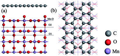 | ||
| Fig. 2 (a) Three kinds of β-MnO2 (110) surfaces: O1 surface, O2 surface, and Mn–O surface. (b) Top view of the G@O1 hybrid structure. | ||
3 Results
First of all, the stability of the three interface structures (G@O1, G@O2, and G@Mn–O) is investigated. For the G@O2 and G@Mn–O structures, the distance between the MnO2 surface and graphene is 3.85 and 3.09 Å, respectively. It is worth noting that the graphene in the two structures is still flat, and MnO2 changes only a little compared to the original MnO2 (110) surface. However for the G@O1 interface structure, two carbon atoms bond to the surface oxygen atoms, as shown in Fig. 3a. The graphene and MnO2 surface is distorted. The nearest C–O distance is 1.48 Å (see Fig. 3b), which is close to the experimental value of the C–O bonding length (1.43 Å).38 It can be concluded that the bonding between carbon and oxygen is covalent bonding. This is also verified by the charge transfer between the carbon and oxygen atoms (see Fig. 3c).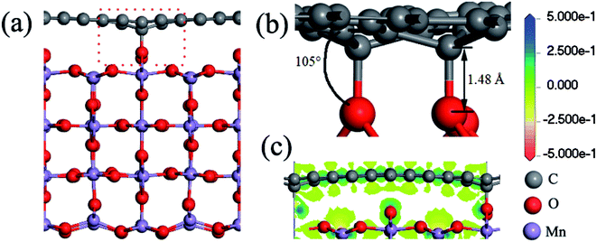 | ||
| Fig. 3 (a) Side view of the G@O1 hybrid structure; (b) detailed view of the interface; (c) charge transfer of the bonded C and O atoms. | ||
Subsequently, the density of states (DOS) is often used to measure the electronic conductivity of the structure.38,39 Fig. 4a and b show that, besides a little gap difference, the total DOS is similar. The total DOS of the MnO2 surface and bulk MnO2 is plotted in Fig. 4a. The calculated band gap of bulk MnO2 is 0.23 eV, narrower than that of the experimental value (0.8 eV),40,41 because DFT always underestimates the band gap. The higher band gap of the MnO2 (110) surface (0.73 eV) is due to the DOS peak being located near the Fermi level of the surface O atoms. It is noteworthy that the MnO2 surface and bulk MnO2 exhibit lower band gaps, which are helpful for the electron transport due to the exhibited semiconductor behavior. The total DOS of the hybrid structure in Fig. 4b, with zero band gap around the Fermi level, shows a conductor behavior. Fig. 4c is the DOS of graphene. The band gap of graphene is 0 eV.
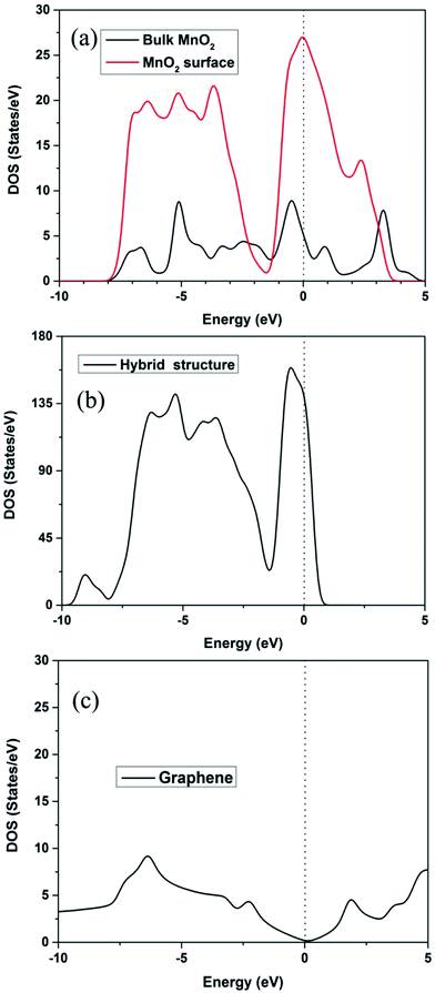 | ||
| Fig. 4 (a) DOS of β-MnO2 (110) surface and bulk; (b) DOS of the hybrid structure; (c) DOS of graphene. | ||
Next, the Li adsorption on the hybrid structure is well investigated. The stability of Li adsorption can be examined by the binding energy, given as Ead = Eh + ELi − Et. Et, Eh, and ELi are the total energies of the hybrid structure after Li adsorption, the hybrid structure and the isolated Li atom, respectively. The different adsorption position of the Li atom in the hybrid structure is plotted in the inset image of Fig. 5, and the binding energy Ead and charge of the Li atom QLi are presented in Fig. 5.
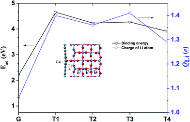 | ||
| Fig. 5 Binding energy and charge of the Li atom at each site. The inset shows the adsorption sites of the Li atoms in a hybrid structure. | ||
The binding energies at the G, T1, T2, T3 and T4 sites in the hybrid structure are about 2.98, 4.65, 4.23, 4.27 and 3.91 eV, respectively. The larger binding energy at the T4 site (3.91 eV) could be attributed to surface adsorption.42 Moreover, the binding energies at the T1, T2, and T3 sites at 4.65, 4.23 and 4.27 eV are due to the synergetic interaction of the MnO2 surface and graphene. Specifically, based on the calculated binding energies at each site, the cathode of the hybrid structure is charged, and the Li atoms probably tend to occupy the interface sites. Mulliken population analysis is always used to analyze the average net charge.43,44 The charge of the Li atom (QLi) was calculated and is plotted in Fig. 5. The value of QLi has a maximum and minimum electron transfer of the Li atom at the T3 site (1.41 e) and the G site (1.06 e).
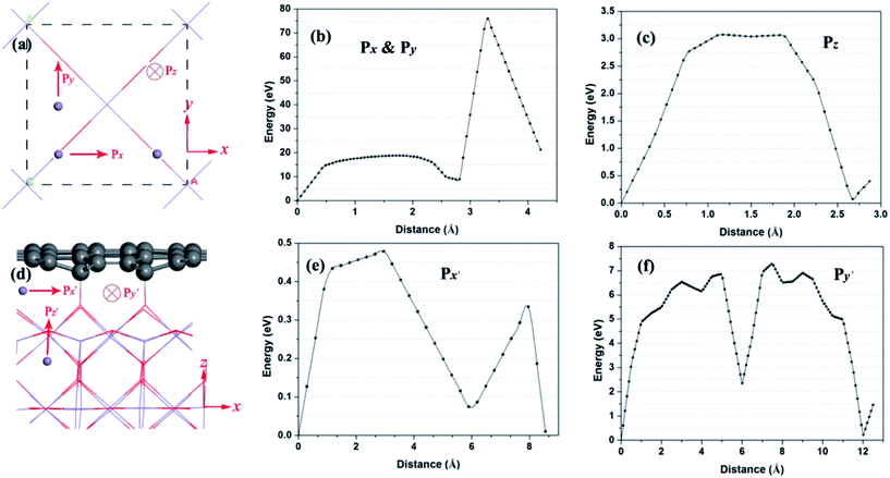
Next, the Li diffusion barriers are calculated in order to thoroughly probe the deintercalation properties of Li with high binding energy near the interface. At the beginning, the Li atom diffusion in bulk MnO2 is investigated, as shown in Fig. 6a. According to the symmetry of bulk MnO2, path x is equivalent to path y. For bulk MnO2, the energy barriers of path x and path z (Fig. 6b and c) are 75.8 and 3.07 eV, respectively. This implies that path z is the main Li diffusion pathway. Fig. 6d shows the Li diffusion near the interface of the hybrid structure. There are three possible pathways (path x′, path y′ and path z′). Fig. 6e and f give the energy barriers of path x′ and path y′. The energy barriers for these two pathways are 0.48 and 7.3 eV, respectively. The Li diffusion from path x′ exhibits the lowest energy barrier. It is worth noting that the energy barrier of path x′ is evidently reduced. Thereafter, the rapid Li diffusion along path x′ in the hybrid structure is feasible.
4 Discussion
The Li diffusion behavior in the graphene and β-MnO2 composite is well investigated using first-principles calculations. As we know, the structure of the electrode materials has a significant effect on the Li diffusion behavior. Indeed, Yang et al. reported that the Mg diffusion pathway on the zigzag MoS2 nanoribbon was identified as passing two adjacent T sites mediated by the nearest neighboring H site in between.45 Therefore, we carefully investigated the interface structure of the graphene and β-MnO2 composite in order to probe the synergistic mechanism of the intercalation or deintercalation of the Li atom.To obtain high power in rechargeable Li ion batteries, it was reported that Li diffusion in or out of the electrode materials was fast enough to supply the electric current in a short time.46 Although there existed many possible diffusion paths in the graphene and β-MnO2 interface structure, it was primarily a one-dimensional channel along the interface, as was the case with Li diffusion in the graphene and SnO2 composite.38 With the combination of Fig. 3a and 6d, only one channel along the interface is observed, and the energy barrier is about 0.48 eV. This implies that the Li atom could easily diffuse through this diffusion path.
As reported in some experimental investigations, Cao et al. fabricated a sandwich-type functionalized graphene sheet-sulfur nanocomposite, and they pointed out that the interface of the nanocomposite had a significant effect on its cycling stability and capacity retention.26 Wang et al. reported that the layer by layer assembly of sandwiched graphene/SnO2 nanorod/carbon nanostructures exhibited ultrahigh lithium ion storage properties, which were attributed to a fast Li diffusion rate in the interfaces.47 Especially, Zhang et al. compounded nitrogen-doped MnO/graphene nanosheets hybrid materials, and they pointed out that the hybrid structure exhibited a reversible electrochemical Li storage capacity as high as 772 mA h g−1 at 100 mA g−1 after 90 cycles.48 However, the diffusion path in bulk β-MnO2 exhibits higher energy barriers for the Li atom, as shown in Fig. 6b and c.
Of course, a detailed diffusion process should take into account numerous variables such as the temperature, pressure and shape of the materials. Given that studying the effect of these factors on the diffusion process was beyond the scope of this investigation, here we just simply aimed to find the lowest possible energy barrier path in the hybrid structure. Indeed, the simulation method was a meaningful tool for providing insight into the Li diffusion in the hybrid structure. The calculated results implied that the pathway along the hybrid structure interface exhibited the lowest energy barrier for Li diffusion, which was consistent with the experimental results.22,42,43 We expected that the simulation results could give positive guidance for experimental investigation.
5 Conclusions
In summary, the structural stability and the electronic and Li diffusion properties of the β-MnO2 and graphene hybrid structure have been investigated in detail. The main findings were summarized as follows: (1) the structural stability and electronic conductivity of the hybrid structure (a stable C–O bond forms between the β-MnO2 (110) plane and graphene) were better than that of β-MnO2. (2) The sites nearby the interface were more fit for Li insertion than other sites in the hybrid structure. (3) The diffusion pathway along the interface of the hybrid structure was treated as a fast pathway for the Li atom. We proposed that the calculated results could give positive guidance for understanding the synergistic mechanism of β-MnO2 and graphene as the cathode of a Li ion battery with high cycle stability and charge/discharge rate.Author contributions
The manuscript was written with contributions from all authors. All authors have given approval to the final version of the manuscript.Acknowledgements
This work is supported by the Foundation of Department of Education of Guizhou province (Grant no. KY [2016] 009).References
- M. Manickam, P. Singh, T. B. Issa, S. Thurgate and R. De Marco, J. Power Sources, 2004, 130, 254–259 CrossRef CAS.
- A. Biswal, B. Chandra Tripathy, K. Sanjay, T. Subbaiah and M. Minakshi, RSC Adv., 2015, 5, 58255–58283 RSC.
- M. Minakshi Sundaram, A. Biswal, D. Mitchell, R. Jones and C. Fernandez, Phys. Chem. Chem. Phys., 2016, 18, 4711–4720 RSC.
- M. V. Reddy, G. V. Subba Rao and B. V. R. Chowdari, Chem. Rev., 2013, 113, 5364–5457 CrossRef CAS PubMed.
- M. S. Whittingham, Chem. Rev., 2004, 104, 4271–4302 CrossRef CAS PubMed.
- A. L. M. Reddy, M. M. Shaijumon, S. R. Gowda and P. M. Ajayan, Nano Lett., 2009, 9, 1002–1006 CrossRef CAS PubMed.
- M. M. Thackeray, S.-H. Kang, C. S. Johnson, J. T. Vaughey, R. Benedek and S. A. Hackney, J. Mater. Chem., 2007, 17, 3112–3125 RSC.
- K. Kang, Y. S. Meng, J. Bréger, C. P. Grey and G. Ceder, Science, 2006, 311, 977–980 CrossRef CAS PubMed.
- Q. Qu, P. Zhang, B. Wang, Y. Chen, S. Tian, Y. Wu and R. Holze, J. Phys. Chem. C, 2009, 113, 14020–14027 CAS.
- C. Xu, B. Li, H. Du, F. Kang and Y. Zeng, J. Power Sources, 2008, 184, 691–694 CrossRef CAS.
- T. Brousse, M. Toupin, R. Dugas, L. Athouël, O. Crosnier and D. Bélanger, J. Electrochem. Soc., 2006, 153, A2171–A2180 CrossRef CAS.
- M. M. Thackeray, Prog. Solid State Chem., 1997, 25, 1–71 CrossRef CAS.
- F. Jiao and P. G. Bruce, Adv. Mater., 2007, 19, 657–660 CrossRef CAS.
- B. Folch, J. Larionova, Y. Guari, C. Guérin and C. Reibel, J. Solid State Chem., 2005, 178, 2368–2375 CrossRef CAS.
- F. Cheng, J. Zhao, W. Song, C. Li, H. Ma, J. Chen and P. Shen, Inorg. Chem., 2006, 45, 2038–2044 CrossRef CAS PubMed.
- D. W. Murphy, F. J. Di Salvo, J. N. Carides and J. V. Waszczak, Mater. Res. Bull., 1978, 13, 1395–1402 CrossRef CAS.
- B. Zachau-Christiansen, K. West, T. Jacobsen and S. Skaarup, Solid State Ionics, 1994, 70, 401–406 CrossRef.
- W. Tang, X. Yang, Z. Liu and K. Ooi, J. Mater. Chem., 2003, 13, 2989–2995 RSC.
- W.-M. Chen, L. Qie, Q.-G. Shao, L.-X. Yuan, W.-X. Zhang and Y.-H. Huang, ACS Appl. Mater. Interfaces, 2012, 4, 3047–3053 CAS.
- X. Wang and Y. Li, J. Am. Chem. Soc., 2002, 124, 2880–2881 CrossRef CAS PubMed.
- M. J. Allen, V. C. Tung and R. B. Kaner, Chem. Rev., 2010, 110, 132–145 CrossRef CAS PubMed.
- D. Wang, D. Choi, J. Li, Z. Yang, Z. Nie, R. Kou, D. Hu, C. Wang, L. V. Saraf, J. Zhang, I. A. Aksay and J. Liu, ACS Nano, 2009, 3, 907–914 CrossRef CAS PubMed.
- D. Wang, R. Kou, D. Choi, Z. Yang, Z. Nie, J. Li, L. V. Saraf, D. Hu, J. Zhang, G. L. Graff, J. Liu, M. A. Pope and I. A. Aksay, ACS Nano, 2010, 4, 1587–1595 CrossRef CAS PubMed.
- K. I. Bolotin, K. J. Sikes, Z. Jiang, M. Klima, G. Fudenberg, J. Hone, P. Kim and H. L. Stormer, Solid State Commun., 2008, 146, 351–355 CrossRef CAS.
- M. D. Stoller, S. Park, Y. Zhu, J. An and R. S. Ruoff, Nano Lett., 2008, 8, 3498–3502 CrossRef CAS PubMed.
- Y. Cao, X. Li, I. A. Aksay, J. Lemmon, Z. Nie, Z. Yang and J. Liu, Phys. Chem. Chem. Phys., 2011, 13, 7660–7665 RSC.
- S. Zhu, H. Zhang, P. Chen, L.-H. Nie, C.-H. Li and S.-K. Li, J. Mater. Chem. A, 2015, 3, 1540–1548 CAS.
- J. Zhang, J. Jiang and X. S. Zhao, J. Phys. Chem. C, 2011, 115, 6448–6454 CAS.
- H. Wang, Q. Zhao, X. Wang, Y. Zhang, J. Gao, Y. Fu, X. Yang and H. Shu, RSC Adv., 2014, 4, 42910–42916 RSC.
- Z.-S. Wu, W. Ren, D.-W. Wang, F. Li, B. Liu and H.-M. Cheng, ACS Nano, 2010, 4, 5835–5842 CrossRef CAS PubMed.
- G. Yu, L. Hu, N. Liu, H. Wang, M. Vosgueritchian, Y. Yang, Y. Cui and Z. Bao, Nano Lett., 2011, 11, 4438–4442 CrossRef CAS PubMed.
- J. Kwon, S. H. Lee, K.-H. Park, D.-H. Seo, J. Lee, B.-S. Kong, K. Kang and S. Jeon, Small, 2011, 7, 864–868 CrossRef CAS PubMed.
- J. Meurig Thomas and P. A. Midgley, Chem. Commun., 2004, 1253–1267 RSC.
- M. D. Segall, J. D. L. Philip, M. J. Probert, C. J. Pickard, P. J. Hasnip, S. J. Clark and M. C. Payne, J. Phys.: Condens. Matter, 2002, 14, 2717 CrossRef CAS.
- S. Jana, S. Basu, S. Pande, S. K. Ghosh and T. Pal, J. Phys. Chem. C, 2007, 111, 16272–16277 CAS.
- M. L. Sushko, K. M. Rosso and J. Liu, J. Phys. Chem. C, 2010, 114, 20277–20283 CAS.
- T. A. Mellan, K. P. Maenetja, P. E. Ngoepe, S. M. Woodley, C. R. A. Catlow and R. Grau-Crespo, J. Mater. Chem. A, 2013, 1, 14879–14887 CAS.
- L. Miao, J. Wu, J. Jiang and P. Liang, J. Phys. Chem. C, 2013, 117, 23–27 CAS.
- M. Minakshi, D. Mitchell, R. Jones, F. Alenazey, T. Watcharatharapong, S. Chakraborty and R. Ahuja, Nanoscale, 2016, 8, 11291–11305 RSC.
- D. A. Tompsett, D. S. Middlemiss and M. S. Islam, Phys. Rev. B: Condens. Matter Mater. Phys., 2012, 86, 205126 CrossRef.
- H. Sato, T. Enoki, M. Isobe and Y. Ueda, Phys. Rev. B: Condens. Matter Mater. Phys., 2000, 61, 3563–3569 CrossRef CAS.
- Q. Zhang, W. Zhang, W. Wan, Y. Cui and E. Wang, Nano Lett., 2010, 10, 3243–3249 CrossRef CAS PubMed.
- R. Zhang, Q. Wang, J. Liang, Q. Li, J. Dai and W. Li, Phys. B, 2012, 407, 2709–2715 CrossRef CAS.
- R. Zhang, Q. Wang, Q. Li, J. Dai and D. Huang, Phys. B, 2011, 406, 3417–3422 CrossRef CAS.
- S. Yang, D. Li, T. Zhang, Z. Tao and J. Chen, J. Phys. Chem. C, 2012, 116, 1307–1312 CAS.
- D. Wang, L.-M. Liu, S.-J. Zhao, B.-H. Li, H. Liu and X.-F. Lang, Phys. Chem. Chem. Phys., 2013, 15, 9075–9083 RSC.
- D. Wang, J. Yang, X. Li, D. Geng, R. Li, M. Cai, T.-K. Sham and X. Sun, Energy Environ. Sci., 2013, 6, 2900–2906 CAS.
- K. Zhang, P. Han, L. Gu, L. Zhang, Z. Liu, Q. Kong, C. Zhang, S. Dong, Z. Zhang, J. Yao, H. Xu, G. Cui and L. Chen, ACS Appl. Mater. Interfaces, 2012, 4, 658–664 CAS.
| This journal is © The Royal Society of Chemistry 2017 |

