 Open Access Article
High-performance supercapacitors based on conductive graphene combined with Ni(OH)2 nanoflakes
Hui Chai a,
Xiao Penga,
Ting Liua,
Xiaohui Sua,
Dianzeng Jia*a and
Wanyong Zhoub
aKey Laboratory of Energy Material, Ministry of Education, Key Laboratory of Advanced Functional Materials, Autonomous Region, Institute of Applied Chemistry, Xinjiang University, Urumqi 830046, Xinjiang, P. R. China. E-mail: huichmails@163.com; jdz0991@gmail.com; Fax: +86 991 858 8883; Tel: +86 991 858 3083
bCollege of Chemistry & Chemical Engineering, Xinjiang University, Urumqi 830046, Xinjiang, P. R. China
First published on 24th July 2017
Abstract
A green and facile strategy is reported for the synthesis of a three-dimensional (3D) graphene nanosheets (GNS)/Ni(OH)2 composite for use as a supercapacitor material. During this process, graphene oxide was reduced to graphene and Ni(OH)2 was attached in it to form the GNS/Ni(OH)2 composite via a chemical precipitation route without any complicated procedures. The product was characterized by X-ray diffraction (XRD) and scanning electron microscopy (SEM). The analyses indicated that the Ni(OH)2 sheets were well interwoven on the surfaces of the graphene nanosheets. Furthermore, the composite was electrochemically tested by cyclic voltammetry, galvanostatic charge/discharge, specific capacitance, and by assessing its cycle life. The GNS/Ni(OH)2 composite exhibited a high specific supercapacitance of 2053 F g−1 at a current density of 0.3 A g−1 in 6 M KOH electrolyte and a long cycle life, along with 97% specific capacitance remaining after 1000 cycles. The GNS/Ni(OH)2 composite had superb electrochemical performance compared to bare Ni(OH)2, which could be attributed to its architecture. These results suggest that the GNS/Ni(OH)2 composite could have potential application as a supercapacitor material.
1. Introduction
Supercapacitors, also known as electrochemical capacitors (ECs), are considered as one of the most promising and reliable power sources for energy storage devices due to their high power density, long lifetime, quick charging capacity, and environmental friendliness.1–4 The energy storage mechanisms of ECs are usually grouped into two types: electrical double-layer capacitance and pseudocapacitance.5,6 Commonly, electrochemical pseudocapacitors with high power, high energy, and long lifetimes can fill the gap between batteries, which provide a higher energy density through the faradic reactions of the electroactive materials, and conventional electrolytic capacitors, which can deliver high power at the cost of low energy storage.7–9Electrode materials play a key role in supercapacitors, and mainly consist of three types: carbon,10–13 transition metal oxides,14,15 and conducting polymers.16,17 Carbonaceous materials are widely used for electrical double-layer capacitors (EDLCs), while metal oxides/hydroxides and conducting polymers are widely used for pseudocapacitors.18,19 In recent years, the growing interest in developing alternative pseudocapacitor electrode materials has created many new approaches, such as metal oxide materials, including manganese oxide,20 cobalt oxide,21,22 nickel oxide,23,24 and nickel hydroxide.25 These are widely utilized as porous or 3D nanostructures. Ni(OH)2 is one of the most promising materials owing to its low cost, high theoretical capacity, good capacity retention, easy electrolyte penetration, and well-defined electrochemical redox activity.26,27 However, some drawbacks still exist with its use, such as poor electrical conductivity and cycle performance caused by volume breakage, and hence more work is needed to improve its electrochemical performance.
Carbon materials possess high electrical conductivity and ductility, which can further improve the capacitive behavior of metal oxide materials and hence these have received much attention by introduction into EC composite electrodes. Graphene28 was discovered by Geim et al. in 2004 (ref. 29) and it constitutes a two dimensional (2D) single-layer of carbon sheets, whose atoms are bonded together in a hexagonal sp2 arrangement.30 Graphene possesses good conductivity, superior mechanical properties, a large specific surface ratio, and excellent chemical stability in various electrolytes.31–34 Due to the above advantages, it was confirmed that graphene has a wide range of potential applications in supercapacitors. Metal oxide/hydroxide and graphene composites as suitable candidate materials for supercapacitors have thus attracted significant research interest.
In this paper, we report a low-cost strategy to synthesize a 3D GNS/Ni(OH)2 composite using a facile and rapid chemical precipitation route without any controlling agent. In previous reports, it was reported that the mass loading values of electrodes materials exert an important impact on the electrocapacitive behavior.35 Among these electrode materials, the GNS/Ni(OH)2 composite with 120 mg GO added demonstrated superimposed layers and a 3D porous structure, with a high specific capacitance of 2053 F g−1 at 0.3 A g−1 when the mass loading value of the electrodes material was 8 mg. The synthesized GNS/Ni(OH)2 composite displayed excellent electrochemical performance even at a high mass loading. Compared with a pure Ni(OH)2 electrode, it also delivered excellent cycling stability, with 97% of its pristine specific capacitance retained after 1000 cycles at a current density of 2.5 A g−1.
2. Experimental section
2.1 Synthesis of the GNS/Ni(OH)2 composite
Graphene oxide (GO) was synthesized from natural graphite powders by a modified Hummer's method.36 Synthesis of the GNS/Ni(OH)2 composite was performed via a chemical precipitation method as follows. First, 0.01 mol of Ni(NO3)2·6H2O and 0.03 mol CO(NH2)2 were added into 100 mL distilled water and treated with ultrasonic waves until a transparent liquid was obtained. Then, 40 mg, 80 mg, and 120 mg of GO was respectively added to the above solution and treated with ultrasonic waves until a suspension presented; the mixture was then kept under magnetic stirring at 95 °C for 16 h and then cooled to room temperature gradually. Subsequently, the black precipitation was filtered, washed with distilled water and absolute alcohol several times, and dried at 80 °C for 12 h in a vacuum oven. At last, the target products of the Ni(OH)2/GNS composite were obtained and termed with NG-1, NG-2, and NG-3 separately. For comparison, pure GNS and pure Ni(OH)2 were prepared by the same method.2.2 Characterization
The structure of the product was characterized by X-ray diffraction (XRD, Bruker D8, λ = 1.5406 Å). The morphology and 3D microstructure of the synthesized composite were observed by scanning electron microscopy (SEM, JSM-6700F, Japan).2.3 Electrochemical measurements
The working electrode was fabricated through mixing the active material, carbon black, and polyfluortetraethylene (PTFE) at a weight ratio of 80![[thin space (1/6-em)]](https://www.rsc.org/images/entities/char_2009.gif) :
:![[thin space (1/6-em)]](https://www.rsc.org/images/entities/char_2009.gif) 15
15![[thin space (1/6-em)]](https://www.rsc.org/images/entities/char_2009.gif) :
:![[thin space (1/6-em)]](https://www.rsc.org/images/entities/char_2009.gif) 5 and then pasted onto nickel foam (1.0 cm × 1.0 cm). A small amount of ethanol was added to the mixture to form a more homogeneous paste. Then, the working electrode was dried at 80 °C for 12 h in a vacuum oven. Each electrode contained about 8 mg of electroactive material. Electrochemical characterization was carried out in a conventional three-electrode cell with 6 M KOH aqueous solution as the electrolyte. Platinum foil was used as the counter electrode and Hg/HgO as the reference electrode. All the electrochemical measurements were conducted using a CHI660 (Shanghai) electrochemical work station.
5 and then pasted onto nickel foam (1.0 cm × 1.0 cm). A small amount of ethanol was added to the mixture to form a more homogeneous paste. Then, the working electrode was dried at 80 °C for 12 h in a vacuum oven. Each electrode contained about 8 mg of electroactive material. Electrochemical characterization was carried out in a conventional three-electrode cell with 6 M KOH aqueous solution as the electrolyte. Platinum foil was used as the counter electrode and Hg/HgO as the reference electrode. All the electrochemical measurements were conducted using a CHI660 (Shanghai) electrochemical work station.
3. Results and discussion
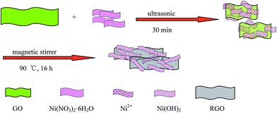
A schematic representation of the formation process of the GNS/Ni(OH)2 composite is shown in Scheme 1.First, CO(NH2)2 and Ni(NO3)2·6H2O were sonicated in water to form a transparent and homogeneous solution of Ni2+ ions and released hydroxyl ions slowly, resulting in the formation of Ni(OH)2, as suggested by the following reactions:
| CO(NH2)2 + 3H2O → 2NH4+ + CO2 + 2OH− | (1) |
| Ni2+ + 2OH− → Ni(OH)2 | (2) |
Then, GO was added to the above mixture. Under magnetic stirring and refluxing, GO was reduced to GNS and uniform Ni(OH)2 was recombined on the surface of the graphene platelets, and during this process, the Ni(OH)2 selectively bonded with carboxyl groups through mutual electrostatic attraction. These composite platelets also prohibited the stacking of graphene sheets by van der Waals' force.37,38
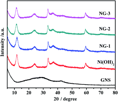
X-ray diffraction measurements were employed to investigate the phase and crystal structure of the synthesized samples, as shown in Fig. 1. As can be seen in Fig. 1, GNS has two peaks that appear at around 28°, which is in accordance with the reported values and which imply that GO has been reduced to GNS and that the oxygen groups have been removed during the chemical precipitation process. According to the Bragg formula, the calculated interlayer spacing is 0.37 nm. Also form Fig. 1, we can see that Ni(OH)2 shows well-defined peaks centered at 11.9°, 24.2°, 33.4°, 35.7°, and 59.6°, corresponding to the (003) (006), (101), (012), and (110) crystal planes of a-Ni(OH)2, respectively. All the peak positions of Ni(OH)2 are consistent with the single phase a-Ni(OH)2 with a rhombohedral structure (JCPDS no. 38-0715)39 and no other impurity peaks were detected. In addition, the XRD patterns of NG-1, NG-2, and NG-3 were similar to bare Ni(OH)2, which perhaps indicates that GNS has almost no impact on the pore regularity of Ni(OH)2. Due to the Ni(OH)2 even being attached to the surface of GNS nanosheets, the characteristics peaks of GNS are not obvious in the composite diffraction spectra pattern.
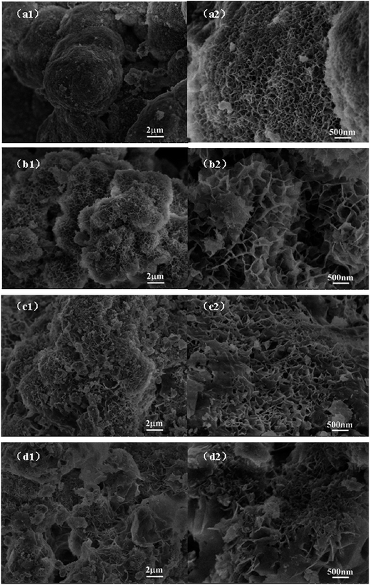
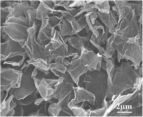
The field emission scanning electron microscopy (FESEM) images of graphene are shown in Fig. 3. The bare Ni(OH)2 (Fig. 2a1 and a2) show a rough surface sphere nanostructure, with the nanostructures stacked atop each other. After combining with graphene, the GNS/Ni(OH)2 composite clearly shows a 3D hierarchical porous structure. Fig. 2b1 and b2 illustrate the NG-1 composite has an obvious nanoflake structure, which has a tendency to reunite at the center. Along with the increasing percentage of graphene content, the NG-2 composite (Fig. 2c1 and c2) has an obvious layer structure and porosity. The samples of NG-3 (Fig. 2d1 and d2) clearly show the superimposed layers, which form 3D porous nanosheets. According to the electrochemical performance mentioned later, the reason for the GNS/Ni(OH)2 composite (NG-3) delivering the best capacitive behavior among these products may be related to its superimposed layers and 3D porous nanosheets structure, which offer numerous electroactive sites for effective electron/ion transport, thus leading to excellent electrochemical performance.
The electrochemical properties of the samples were characterized by cyclic voltammogram (CV), galvanostatic charge/discharge, specific capacitance and cycle life measurements. All the measurements were carried out in a three-electrode system with Hg/HgO (in 6 M KOH) as the reference electrode. Fig. 4 shows the CV curves of pure Ni(OH)2, NG-1, NG-2, and NG-3 composite materials electrode with the potential varying from 0 to 0.65 V at a scan rate of 5 mV s−1. The CV curve of pure Ni(OH)2 is apparently narrower and has lower redox peaks than that of the GNS/Ni(OH)2 composites at the same scan rate, indicating the smaller specific capacitances and poor reversibility. With the increase in GNS content, the cyclic voltammetry curve showed obvious redox peaks, good symmetry, and large specific capacitances. It can be interpreted that the introduction of GNS increases the capacitance value, mainly through increasing the conductivity of the Ni(OH)2. The redox peaks observed in the CV curve of Ni(OH)2 were due to the following Faradaic reactions:40,41
| α-Ni(OH)2 + OH− ↔ γ-NiOOH + H2O + e− |
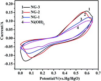 | ||
| Fig. 4 CV curves of the Ni(OH)2, NG-1, NG-2, and NG-3 composite materials at a scan rate of 5 mV s−1. | ||
During the process, the anodic peak is caused by the oxidation reactions where α-Ni(OH)2 is converted into γ-NiOOH, while the cathodic peak is caused by the inverse reduction reaction.
Galvanostatic charge–discharge measurements were performed at a current density of 0.3 A g−1. The discharge curves of the Ni(OH)2, NG-1, NG-2, and NG-3 composites are shown in Fig. 5. The specific capacitance was calculated by C = I × t/(V = m), where C is the specific capacitance, I is the discharging current, t is the discharge time, V is the potential drop during discharge, and m is the mass of the active material in a single electrode. The specific capacitance values of the Ni(OH)2, NG-1, NG-2, and NG-3 composite electrode were 1500 F g−1, 1637 F g−1, 1944 F g−1, and 2053 F g−1, respectively. These results were consistent with the cyclic voltammetry tests, where the specific capacitance of the composites as electrode material was higher than that of bare Ni(OH)2, with the NG-3 composite having the highest specific capacitance, which indicate that GNS can act as a highly conductive medium, providing much more flexible layers with an enlarged interlayer space and increased surface area, thus benefiting the electrochemical performance of the composite.37 Moreover, the improved specific capacitance was attributed to the 3D loose structure of the composite, which provides more active sites for the redox reaction of the active materials and more interfacial contact with the electrolyte, thus facilitating fast electron transfer between the active materials and the charge collector, leading to fast electron and ion transmission to the electrode.42,43
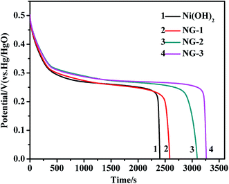 | ||
| Fig. 5 The galvanostatic discharge curves of the Ni(OH)2, NG-1, NG-2, and NG-3 composite materials at a current density of 0.3 A g−1. | ||
The current density was varied and the obtained specific capacitances at different current densities are shown in Fig. 6. It can be seen that the specific capacitance decreases with the increase in the current densities ranging from 0.3 to 3.7 A g−1, and the capacitance of the NG-3 composite is always higher than that of the pure Ni(OH)2, NG-1, and NG-2. At the current density of 3.7 A g−1, the specific capacitance of NG-3 (1297 F g−1) was 95% of that of at current density of 2.5 A g−1, while Ni(OH)2, NG-1, and NG-2 were 74%, 85%, and 87%, respectively. It can be interpreted that the electrical conductivity is closely associated with the porous channels. These porous channels provide more effective contact between the active materials and the electrolyte in sample NG-3, which leads to its outstanding electrochemical property and good rate performance.
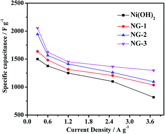 | ||
| Fig. 6 Specific capacitance of the Ni(OH)2, NG-1, NG-2 and NG-3 composite materials at various current densities. | ||
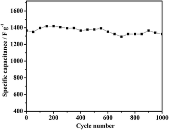
The cycle life is another important factor for supercapacitor electrode materials. Fig. 7 shows the cyclability of the NG-3 composite over 1000 cycles between 0 and 0.5 V at a discharge current density of 2.5 A g−1. Evidently, after 150 cycles, the utilization of active material reached the highest level and the specific capacitance reaches its highest level with the electrolyte gradually being penetrated. The lowest specific capacitance after 1000 cycles still retains 97% of the maximum capacitance, which is higher than that for pure Ni(OH)2 (1377 F g−1 with 63%). The cycling test suggests that the NG-3 composite electrode has high stability for long-term applications. The excellent capacitive behavior of the psuedocapacitor most likely arises from both a good synergistic effect between GNS and Ni(OH)2 and the electric conductivity of the hierarchically porous structure, which yields an aggregation-free NG-3 composite, prompts the redox reaction to be more effective at the GNS/Ni(OH)2 electrode surface and electrolyte interface, and facilitates effective charge transport as well as maintaining the mechanical integrity of the overall electrode for fast energy storage and delivery.
In comparison with the other results listed in Table 1, the as-prepared GNS/Ni(OH)2 delivers an excellent specific capacitance even at a high mass loading, which gives rise to the potential for these materials to serve as new and attractive active materials for wide application in supercapacitors.
| Electrode | Specific capacitance | Capacitance retention | Electroactive material | Electrolyte | Ref. |
|---|---|---|---|---|---|
| α-Ni(OH)2/graphite | 1956 F g−1 (1 A g−1) | 70% (10 A g−1, 1000 cycles) | KOH (6 M) | 39 | |
| α-Ni(OH)2/rGO | 521 F g−1 (50 mV s−1) | 87.9% (50 mV s−1, 1000 cycles) | KOH (6 M) | 44 | |
| Ni(OH)2/graphene | 166 F g−1 (0.5 A g−1) | 65% (10 A g−1, 1000 cycles) | KOH (6 M) | 45 | |
| 3D graphene/Ni(OH)2 | 718.2 F g−1 (6.7 A g−1) | 84.2% (10 A g−1, 500 cycles) | 1 mg | KOH (6 M) | 46 |
| graphene/Ni(OH)2 | 1247 F g−1 (5 mV s−1) | 95% (16 A g−1, 2000 cycles) | 5 mg | KOH (6 M) | 47 |
| (Ni(OH)2/rGO | 1886 F g−1 (5 A g−1) | 70% (10 A g−1, 1000 cycles) | KOH (3 M) | 48 | |
| GNS/Ni(OH)2 | 1985.1 F g−1 (5 mA cm−2) | 93.5% (30 mA cm−2, 500 cycles) | 6 mg | KOH (6 M) | 49 |
| Our GNS/Ni(OH)2 | 2053 F g−1 (0.3 A g−1) | 97% (2.5 A g−1, 1000 cycles) | 8 mg | KOH (6 M) | Ours |
4. Conclusions
In this work, we developed a hierarchically porous GNS/Ni(OH)2 composite and demonstrated the composite as a promising electrode material for high-performance pseudocapacitors with good electrochemical performance and long cycle life. The overall electrochemical performance of the composite was drastically improved compared to bare Ni(OH)2 and graphene. The excellent capacitive performances result from the incorporation of nanoflake pseudocapacitive Ni(OH)2 into a three-dimensional graphene network. The porous structure facilitates excellent electronic/ionic conductivity and large interfaces between active materials and electrolyte, which takes full advantage of the pseudocapacitance of Ni(OH)2 and the conductivity of GNS. In addition, the porous network obviously improves the mechanical rigidity and electrochemical stability of the GNS/Ni(OH)2. Therefore, the specific capacitance of the composite is improved, which makes it a promising electrode material for high-performance alkaline rechargeable supercapacitors.Acknowledgements
This work was supported by Natural Science Foundation of Xinjiang Uygur Autonomous Region (No. 2015211c250).References
- Y. Wang and Y. Xia, Adv. Mater., 2013, 25, 5336 CrossRef CAS PubMed.
- C. Z. Yuan, B. Gao, L. F. Shen, S. D. Yang, L. Hao, X. J. Lu, F. Zhang, L. J. Zhang and X. G. Zhang, Nanoscale, 2011, 3, 529 RSC.
- O. Y. Tian, K. Cheng, F. Yang, L. M. Zhou, K. Zhu, K. Ye, G. L. Wang and D. X. Cao, J. Mater. Chem. A, 2017, 5, 14551 Search PubMed.
- H. N. Jia, J. H. Lin, Y. L. Liu, S. L. Chen, Y. F. Cai, J. L. Qi, J. C. Feng and W. D. Fei, J. Mater. Chem. A, 2017, 5, 10678 CAS.
- C. Liu, F. Li, L. P. Ma and H. M. Cheng, Adv. Mater., 2010, 22, E28 CrossRef CAS PubMed.
- D. Choi, G. E. Blomgren and P. N. Kumta, Adv. Mater., 2006, 18, 1178 CrossRef CAS.
- M. S. Javed, J. Chen, L. Chen, Y. Xi, C. L. Zhang, B. Y. Wan and C. G. Hu, J. Mater. Chem. A, 2016, 4, 667 CAS.
- X. Y. Lang, A. Hirata, T. Fujita and M. W. Chen, Adv. Energy Mater., 2014, 4, 1301809 CrossRef.
- G. Wang, L. Zhang and J. Zhang, Chem. Soc. Rev., 2012, 41, 797 RSC.
- Q. Q. Zhou, X. Y. Chen and B. Wang, Microporous Mesoporous Mater., 2012, 158, 155 CrossRef CAS.
- X. Y. Chen and Q. Q. Zhou, Electrochim. Acta, 2012, 71, 92 CrossRef CAS.
- Y. Huang, J. J. Liang and Y. S. Chen, Small, 2012, 8, 1805 CrossRef CAS PubMed.
- C. Zheng, W. Z. Qian, C. J. Cui, Q. Zhang, Y. G. Jin, M. Q. Zhao, P. H. Tan and F. Wei, Carbon, 2012, 50, 5167 CrossRef CAS.
- J. P. Liu, J. Jiang, C. W. Cheng, H. X. Li, J. X. Zhang, H. Gong and H. J. Fan, Adv. Mater., 2011, 23, 2076 CrossRef CAS PubMed.
- R. Z. Li, X. Ren, F. Zhang, C. Du and J. P. Liu, Chem. Commun., 2012, 48, 5010 RSC.
- H. R. Ghenaatian, M. F. Mousavi and M. S. Rahmanifar, Electrochim. Acta, 2012, 78, 212 CrossRef CAS.
- R. B. Rakhi, W. Chen and H. N. Alshareef, J. Mater. Chem., 2012, 22, 5177 RSC.
- L. L. Zhang and X. S. Zhao, Chem. Soc. Rev., 2009, 38, 2520 RSC.
- G. Wang, L. Zhang and J. Zhang, Chem. Soc. Rev., 2012, 41, 797 RSC.
- X. H. Yang, Y. G. Wang, H. M. Xiong and Y. Y. Xia, Electrochim. Acta, 2007, 53, 752 CrossRef CAS.
- S. Xiong, C. Yuan, X. Zhang, B. Xi and Y. Qian, Chem.–Eur. J., 2009, 15, 5320 CrossRef CAS PubMed.
- X. Xia, J. Tu, Y. Mai, X. Wang, C. Gu and X. Zhao, J. Mater. Chem., 2011, 21, 9319 RSC.
- C. Yuan, X. Zhang, L. Su, B. Gao and L. Shen, J. Mater. Chem., 2009, 19, 5772 RSC.
- W. Wen, J. M. Wu and M. H. Cao, Nano Energy, 2013, 2, 1383 CrossRef CAS.
- L. Cao, L. B. Kong, Y. Y. Liang and H. L. Li, Adv. Mater., 2004, 16, 1853 CrossRef CAS.
- H. L. Wang, H. S. Casalongue, Y. Y. Liang and H. J. Dai, J. Am. Chem. Soc., 2010, 132, 7472 CrossRef CAS PubMed.
- L. Wang, X. Li, T. Guo, X. Yan and B. K. Tay, Int. J. Hydrogen Energy, 2014, 39, 7876 CrossRef CAS.
- H. Wang, C. M. Holt, Z. Li, X. Tan, B. S. Amirkhiz, Z. Xu, B. C. Olsen, T. Stephenson and D. Mitlin, Nano Res., 2012, 5, 605 CrossRef CAS.
- K. S. Novoselov, A. K. Geim, S. V. Morozov, D. Jiang, Y. Zhang, S. V. Dubonos, I. V. Grigorieva and A. A. Firsov, Science, 2004, 306, 666 CrossRef CAS PubMed.
- X. F. Gao, J. Jiang and S. Nagas, J. Phys. Chem. C, 2010, 114, 832 CAS.
- D. Chen, L. Tang and J. Li, Chem. Soc. Rev., 2010, 39, 3157 RSC.
- M. Pumera, Energy Environ. Sci., 2011, 4, 668 CAS.
- Y. Sun, Q. Wu and G. Shi, Energy Environ. Sci., 2011, 4, 1113 CAS.
- L. S. Zhang, L. Y. Jiang, H. J. Yan, W. D. Wang, W. Wang, W. G. Song, Y. G. Guo and L. J. Wan, J. Mater. Chem., 2010, 20, 5462 RSC.
- X. C. Li, J. J. Shen, W. Sun, X. D. Hong, R. T. Wang, X. H. Zhao and X. B. Yan, J. Mater. Chem. A, 2015, 3, 13244 CAS.
- W. S. Hummers and R. E. Offeman, J. Am. Chem. Soc., 1958, 80, 1339 CrossRef CAS.
- T. Liu, H. Chai, D. Jia, Y. Su, T. Wang and W. Zhou, Electrochim. Acta, 2015, 180, 998 CrossRef CAS.
- X. Su, H. Chai, D. Jia, S. J. Bao, W. Y. Wan and M. L. Zhou, New J. Chem., 2013, 37, 439 RSC.
- J. T. Zhang, S. Liu, G. L. Pan, G. R. Li and X. P. Gao, J. Mater. Chem. A, 2014, 2, 1524 CAS.
- S. Yang, X. Wu and C. Chen, Chem. Commun., 2012, 48, 2773 RSC.
- A. Ning, Y. An, Z. Hu, B. Guo, Y. Yang and Z. Lei, J. Mater. Chem. A, 2015, 3, 22239 Search PubMed.
- J. Yan, T. Wei, W. M. Qiao, B. Shao, Q. K. Zhao, L. J. Zhang and Z. J. Fan, Electrochim. Acta, 2010, 55, 6973 CrossRef CAS.
- Z. J. Fan, J. Yan, T. Wei, L. J. Zhi, G. Q. Ning, T. Y. Li and F. Wei, Adv. Funct. Mater., 2011, 21, 2366 CrossRef CAS.
- J. W. Lee, T. Ahn, D. Soundararajan, J. M. Ko and J. D. Kim, Chem. Commun., 2011, 47, 6305 RSC.
- J. Y. Ji, L. L. Zhang, H. X. Ji, Y. Li, X. Zhao, X. Bai, X. B. Fan, F. B. Zhang and R. S. Ruoff, ACS Nano, 2013, 7, 6237 CrossRef CAS PubMed.
- C. H. Jiang, B. B. Zhan, C. Li, W. Huang and X. C. Dong, RSC Adv., 2014, 4, 18080 RSC.
- Y. X. Xu, X. Q. Huang, Z. Y. Lin, X. Zhong, Y. Huang and X. F. Duan, Nano Res., 2013, 6(1), 65 CrossRef CAS.
- X. X. Zang, C. C. Sun, Z. Y. Dai, J. Yang and X. C. Dong, J. Alloys Compd., 2017, 691, 144 CrossRef CAS.
- H. J. Yan, J. W. Bai, J. Wang, X. Y. Zhang, B. Wang, Q. Liu and L. H. Liu, CrystEngComm, 2013, 15, 10007 RSC.
| This journal is © The Royal Society of Chemistry 2017 |

