 Open Access Article
Creative Commons Attribution 3.0 Unported Licence
Intramolecular alkyne–dithiolium cycloaddition: a joint experimental and DFT mechanistic study†
Cheng Wang ,
Christopher Flinn
 and
Yuming Zhao
 *
*
Department of Chemistry, Memorial University, St. John's, NL, Canada A1B 3X7. E-mail: yuming@mun.ca; Fax: +1 709 864 3702; Tel: +1 709 864 8747
First published on 25th July 2017
Abstract
We previously by serendipity discovered a unique intramolecular alkyne–dithiolium cycloaddition, through which phenyldithiafulvenes carrying ortho-alkynyl substituents were directly transformed into complex polycyclic aromatic structures [Wang and Zhao, Org. Biomol. Chem. 2015, 13, 9575–9579]. In this work, we carried out a joint experimental and theoretical study on the mechanisms of this type of reaction and our results showed that protic acid and oxidant (iodine) are important agents promoting the cycloaddition and subsequent elimination steps. Moreover, the degree of π-conjugation around the alkynyl group was identified to play a key role in driving the cycloaddition. Monoyne without further π-conjugation would react with the dithiolium ring through a concerted 1,3-dipolar cycloaddition transition state, whereas 1,3-butadiyne prefers to undergo a stepwise Prins-type cyclization pathway with a significantly lowered activation energy barrier as a result of the resonance stabilizing effect on the transition state provided by the additional alkynyl unit.
1 Introduction
1,4-Dithiafulvenes (DTFs) because of their excellent electron-donating properties1–4 have been increasingly employed over the past years as active components in organic optoelectronic materials and devices such as chemical sensors,5–11 molecular switches,12–15 non-linear optic-phores,16 photovoltaic cells,17–23 field-effect transistors (FETs),24–26 and so forth. Besides acting as π-electron donors, DTFs also provide synthetic access to another intriguing class of tetrathiafulvalene (TTF) analogues, namely tetrathiafulvalene vinylogues (TTFVs), through a straightforward oxidative dimerization reaction.8,27–29 As illustrated in Scheme 1, a phenyl-substituted DTF 1 can readily undergo single-electron transfer to yield a radical cation intermediate, in which the non-aromatic dithiole group is converted into an aromatic dithiolium ion. The radical moiety then dimerizes to form a TTFV dication [2]2+. Such oxidative dimerization reactivity has been widely used as a synthetic tool in the preparation of various redox-active functional molecular/macromolecular systems, including π-conjugated oligomers,30 polymers,5,31–34 and shape-persistent macrocycles.35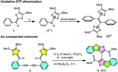 | ||
| Scheme 1 Typical oxidative dimerization of phenyl-DTF 1 and an unusual iodine-promoted cycloaddition of bis(DTF)-diphenylbutadiyne 3. | ||
While the aryl-substituted DTFs reported so far generally follow the reactivity of oxidative dimerization as shown in Scheme 1, there have been anomalies observed in a number of cases.35–37 In a recent study we discovered an unexpected reaction when treating a bis(DTF)-substituted diphenylbutadiyne 3 with iodine (Scheme 1).38 Rather than the expected DTF dimerization products, the reaction surprisingly produced a major product (4) that features a unique tricyclic indenothiophene motif. The newly formed rings (B and C) in 4 are supposedly constructed through an intramolecular cycloaddition process,39,40 while the sp3 benzylic carbon of the B ring hints at a protonation step taking place on the vinylic carbon adjacent to the dithiole group of 3 at the initial stage of the reaction.41–43 Mechanistically, two plausible reaction pathways can be proposed to account for the reaction outcome. As depicted in Scheme 2, protonation of compound 3 results in the formation of a dithiolium intermediate IM-1. The acid here is believed to come from the redox reactions between 3 and iodine,29 which leads to other unidentified byproducts. Once formed the dithiolium moiety of IM-1 can quickly react with the ortho-alkynyl group due to its close proximity. From IM-1 the reaction can possibly proceed through two approaches based on commonly known organic reaction mechanisms. The first reaction pathway is a concerted 1,3-dipolar cycloaddition39,40 that directly leads to a cage-shaped intermediate IM-3 with the backbones of B and C rings assembled simultaneously. The second one is a stepwise pathway, in which the alkynyl group attacks the carbocation of dithiolium ring via an alkyne Prins-type cyclization44–49 at first. The electrophilic cyclization occurs with a 5-exo-dig regioselectivity, forming the B ring only. The resulting intermediate IM-2 then undergoes another step of intramolecular nucleophilic addition to furnish intermediate IM-3, which after a ring opening step yields a cationic intermediate IM-4. At the final stage of the reaction, a dethiomethylation process occurs yielding the indenothiophene product P-1.
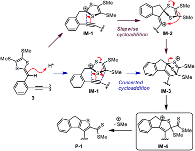 | ||
| Scheme 2 Two plausible reaction mechanisms for the intramolecular alkynye–dithiolium cycloaddition of compound 3. | ||
With the plausible reaction mechanisms proposed, fundamentally important questions naturally follow. (i) The acid seems to be an essential agent in the reaction, if either of the hypothesized mechanisms holds true. So, will the introduction of a protic acid to the reaction make an improvement on reaction rate and yield? (ii) Does the intramolecular alkyne–dithiolium cycloaddition prefer the concerted or stepwise pathway? (iii) How does the dethiomethylation happen at the final stage of the reaction? (iv) Is iodine a necessary agent to the reaction as well? This paper is hence aimed at addressing these mechanistic issues through a joint experimental and computational study.
2 Results and discussion
2.1 The role of protic acid on cycloaddition
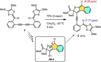
We first investigated the role of protic acid in the intramolecular cycloaddition of compound 3. A strong organic acid, trifluoroacetic acid (TFA), was chosen in our experiments based on its known ability to effectively protonate DTF moieties in nonpolar organic media.50–52 Experimentally, dropwise addition of TFA to the solution of 3 in CH2Cl2 quickly led to a color change from yellowish to dark red. The reaction occurred at a very fast rate. At −20 °C, compound 3 was completely consumed within 5 min as monitored by thin-layer chromatographic (TLC) analysis. Aqueous workup followed by silica column separation afforded product 5 as a red-color solid. Compound 5 has limited chemical stability and was observed to slowly decompose within a duration of a few days. Nevertheless, the structure of 5 could still be convincingly elucidated based on its spectroscopic data; in particular, the two distinctive singlets at 6.26 and 7.17 ppm in the 1H NMR spectrum of 5 (see ESI†) can be clearly assigned to the indenyl and vinyl protons respectively. The two proton signals show nearly equal integral values, confirming that only a half of compound 3 has cyclized under the TFA treatment. The formation of an indenyl moiety in 5 can be rationalized by a β-hydrogen elimination on the reactive intermediate IM-4 mentioned in Scheme 2. Obviously, a strong protic acid can substantially accelerate the intramolecular alkyne–dithiolium cycloaddition, but it does not seem to be very effective at promoting the subsequent SMe elimination. Without removal of a SMe group, the remaining alkynyl unit of 5 is prohibited from going through another step of intramolecular cycloaddition due to the steric hindrance surrounding it.2.2 The reactivity of monoyne and diyne to cycloaddition
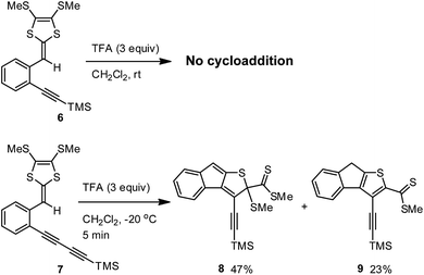
To check whether the TFA-promoted intramolecular cycloaddition would generally occur on ortho-alkynyl substituted aryl-DTFs, two simple model compounds 6 and 7 were prepared and then subjected to TFA treatment in CH2Cl2 (Scheme 4). Upon addition of excess TFA, the solution of compound 6 turned into a red color quickly at −20 °C. After 5 min, the mixture was worked up with aqueous NaHCO3 and checked by TLC analysis. To our surprise, only starting material 6 was present and there were no other meaningful products detected. Running the reaction at room temperature with a prolonged reaction time (12 hours) still gave the same result. Clearly, compound 6 is devoid of the acid-promoted intramolecular cyclization reactivity.Comparing the structures of compounds 3 and 6, one can easily tell that their alkynyl units are different in terms of π-conjugation degree. At this juncture, it is reasoned that the extended π-conjugation of the 1,3-butadiynylene segment in 3 has an important effect on the reactivity, most likely the key transition state(s) involved in the cyclization is stabilized by the extended π-conjugation at the alkynyl group to result in lower activation energy barrier(s). This hypothesis is substantiated by the experimental observation that ortho-diyne substituted phenyl-DTF 7 was quickly consumed upon treatment with excess TFA in CH2Cl2 at −20 °C, yielding two compounds 8 and 9 as the major products in an approximately 2![[thin space (1/6-em)]](https://www.rsc.org/images/entities/char_2009.gif) :
:![[thin space (1/6-em)]](https://www.rsc.org/images/entities/char_2009.gif) 1 molar ratio (Scheme 4). Both of the cyclized products, although with limited chemical stability, were able to be isolated by silica column chromatography to yield relatively pure samples for NMR, IR, and MS analyses. Mechanistically, compound 9 can be reasonably ascribed to the product resulting from dethiomethylation of 8, and this SMe elimination step appears to more readily occur than in the case of 3.
1 molar ratio (Scheme 4). Both of the cyclized products, although with limited chemical stability, were able to be isolated by silica column chromatography to yield relatively pure samples for NMR, IR, and MS analyses. Mechanistically, compound 9 can be reasonably ascribed to the product resulting from dethiomethylation of 8, and this SMe elimination step appears to more readily occur than in the case of 3.
2.3 The role of iodine in elimination of SMe
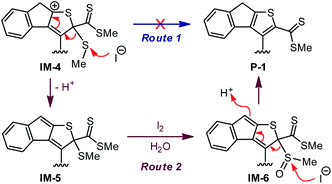
In the reaction of 3 to 4 shown in Scheme 1, iodine is believed to play a vital role in accelerating the dethiomethylation step as compared with the outcome of the TFA-promoted reaction of 3 in Scheme 3. The removal of SMe can be proposed to occur through a simple elimination mechanism (Route 1, Scheme 5) in which iodide anion acts as a nucleophile to directly attack the SMe group. To probe whether this is a valid mechanism, a control reaction was conducted in which excess TFA and KI were co-added to the CH2Cl2 solution of 3. The reaction was run at −20 °C for as long as 4 hours, but the outcome showed no significant differences from the reaction with only TFA added. This observation hence rules out Route 1 (Scheme 5) as the actual dethiomethylation mechanism.In an alternative control experiment, compound 3 was first treated with excess TFA (6 equiv.) in CH2Cl2 at −20 °C for 5 min. Iodine (1 equiv.) was then added and the reaction mixture was kept at −20 °C for another 10 min. After a reductive workup with aqueous Na2S2O3, compound 4 was obtained in 54% isolated yield. Compared with the reaction shown in Scheme 1, the use of TFA in combination with iodine did make a significant improvement on both reaction rate and yield, hence offering a useful synthetic method for constructing complex tricyclic indenothiophene skeletons.53–56 Experimental results so far have confirmed that direct dethiomethylation cannot occur easily under non-oxidative conditions. The presence of an oxidant, such as iodine, has a crucial effect on this step. As iodine has been known to induce the oxidation of thioether into sulfoxide,57,58 another elimination mechanism (Route 2, Scheme 5) is then proposed. After the acid-promoted alkyne–dithiolium cycloaddition, an oxidation reaction on the SMe group of IM-5 ensues to afford intermediate IM-6. Conversion of the SMe into sulfoxide leads to enhanced electrophilicity, which in turn facilitates nucleophilic attack at the sulfoxide group (e.g., by iodide anion) to produce the indenothiophene product P-1. The mechanism depicted in Route 2 agrees reasonably with the experimental observations as well as known chemistry reported in the literature, but there is still a lack of concrete proof for this mechanism being the actual operative one. More systematic studies are warranted to gain deeper insight in this respect. Nevertheless, it is clear at this stage of research that oxidation of the cyclized intermediate(s) by iodine accelerates the dethiomethylation step. For the reaction of model compound 7 shown in Scheme 4, dethiomethylated product 9 was formed without the presence of any deliberately added oxidant. Since the reaction was run under open air, the elimination of SMe in this case does not contradict the mechanism of Route 2. Molecular oxygen diffused in the reaction solution is believed to act as an oxidant59 facilitating the SMe elimination therein.
2.4 DFT studies of the intramolecular alkyne–dithiolium cycloaddition
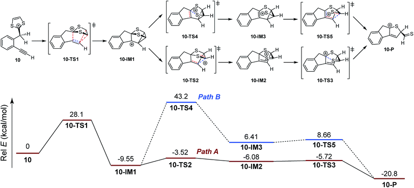
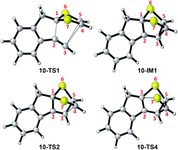
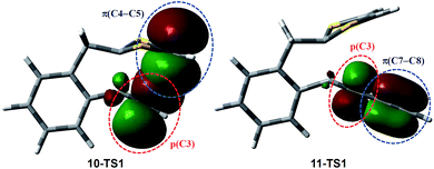
So far, our investigations have shed light on several important aspects related to the intramolecular alkyne–dithiolium cycloaddition, but the experimental data do not unveil much of the mechanistic details involved in the key cyclization process that transforms the alkynyl–dithiolium intermediate into a fused tricyclic indenodihydrothiophene cation. As proposed in Scheme 2, the reaction from IM-3 to IM-4 can possibly follow two different cycloaddition mechanisms, namely stepwise and concerted. Which one would be energetically more favored is a question of great fundamental importance. To answer it, density functional theory (DFT) calculations have been undertaken in order to map out the detailed reaction potential energy surfaces. Two model compounds 10 and 11 were adopted herein to simulate the actual compounds 6 and 7 tested in our experimental work. Our computational survey was only focused on the stationary points (intermediates and transition states) involved in the processes from protonated phenyl-DTFs 10 and 11 to their corresponding indenohydrothiophene cation products.Scheme 6 shows the DFT calculated reaction pathways and energy profiles for the intramolecular cycloaddition of monoyne-substituted dithiolium 10. The reaction first overcomes a transition state 10-TS1 with an activation energy barrier of 28.1 kcal mol−1, leading to a cage-like cationic intermediate 10-IM1. The structure of 10-TS1 (Fig. 1) exhibits a concerted asynchronous cycloaddition feature, wherein the distance between C1–C2 is significantly shorter than those of C3–C4 and C3–C5 (see Table 1 for detailed geometric data). The distances of C3–C4 and C3–C5 are identical, rendering the transition state 10-TS1 a mirror symmetry. The development of the C1–C2 bond is associated with notable distortion of the ditholium ring, allowing the π-bond of C4–C5 to have orbital interactions with the empty p-orbital at the C3 carbon. Natural Bond Orbital (NBO) analysis60,61 shows that the donor–acceptor orbital interactions between π(C4–C5) and p(C3) provide stabilization energy of 12.62 kcal mol−1 to the transition state (Fig. 3). According to intrinsic reaction coordinate (IRC) analysis,62,63 transition state 10-TS1 is directly connected to a relatively stable intermediate 10-IM1 in which the carbon atoms C3, C4, and C5 are bonded to one another to form a three-membered ring. Intermediate 10-IM1 is then subject to sequential bond breaking at the C3–C4 and C1–S7 bonds give product 10-P. Two reaction pathways (A and B, Scheme 6) were found by the DFT calculations. In pathway A the first step is the C3–C4 bond cleavage going through transition state 10-TS2, while pathway B begins with the breaking of C1–S7 bond. Pathway A is believed to be the favored one, since it has an energy barrier (6.03 kcal mol−1) considerably lower than that of pathway B (52.75 kcal mol−1).
| 10-TS1 | 10-IM1 | 10-TS2 | 10-TS4 | |
|---|---|---|---|---|
| C1–C2 | 1.83 | 1.51 | 1.54 | 1.37 |
| C2–C3 | 1.26 | 1.44 | 1.38 | 1.46 |
| C3–C4 | 2.79 | 1.56 | 2.00 | 1.55 |
| C3–C5 | 2.79 | 1.56 | 1.53 | 1.53 |
| C4–C5 | 1.37 | 1.49 | 1.48 | 1.49 |
| C4–C7 | 1.73 | 1.83 | 1.73 | 1.81 |
| C5–C6 | 1.73 | 1.83 | 1.84 | 1.85 |
| C1–S6 | 1.79 | 1.85 | 1.83 | 1.86 |
| C1–S7 | 1.79 | 1.85 | 1.90 | 2.46 |
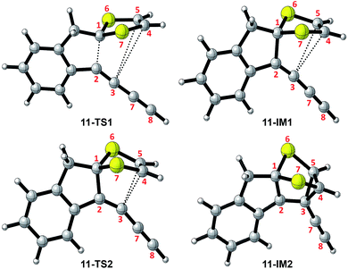
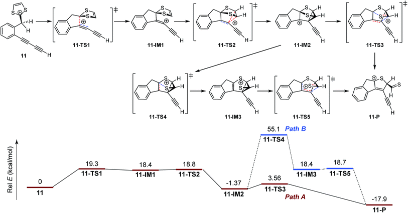
The mechanistic details for the intramolecular cycloaddition of diyne-substituted dithiolium 11 are depicted in Scheme 7. Unlike the reaction mechanism of monoyne 10, compound 11 undergoes the cycloaddition in a stepwise manner. In the first step, the C2–C3 alkynyl group attacks the C1 carbocation of the dithiolium ring, leading to a cationic intermediate 11-IM1. This is a mechanism typical of the Prins-type cyclization reactions.44–49 The transition state of this process (11-TS1) clearly reveals a new σ bond formed between C1–C2 (see Fig. 2 and Table 2), but the distances at C3–C4 and C3–C5 (3.60 Å and 3.65 Å) are, in contrast to the case of 10, beyond the van der Waals contact and hence indicate little covalent interactions. NBO analysis shows that in transition state 11-TS1 there is vinyl cation character64–66 developing on C3, which is stabilized by the neighboring alkynyl group (C7–C8) through resonance effect. The donor–acceptor orbital interactions in 11-TS1 (depicted in Fig. 3) are calculated to deliver 55.50 kcal mol−1 stabilization energy. The stabilization by such a resonance effect allows the transition state to avert distorting its dithiolium ring for the π(C4–C5) → p(C3) interactions as in the case of monoyne 10-TS. Indeed, the stabilizing effect by the extra alkynyl group significantly lowers the activation energy barrier (Ea) for the cyclization of diyne 11 by 8.8 kcal mol−1 in comparison with that of monoyne 10.
| 11-TS1 | 11-IM1 | 11-TS2 | 11-IM2 | |
|---|---|---|---|---|
| C1–C2 | 1.84 | 1.63 | 1.58 | 1.51 |
| C2–C3 | 1.27 | 1.30 | 1.32 | 1.45 |
| C3–C4 | 3.60 | 3.01 | 2.48 | 1.58 |
| C3–C5 | 3.65 | 3.01 | 2.48 | 1.58 |
| C4–C5 | 1.35 | 1.37 | 1.39 | 1.48 |
| C4–C7 | 1.74 | 1.74 | 1.74 | 1.82 |
| C5–C6 | 1.74 | 1.74 | 1.74 | 1.82 |
| C1–S6 | 1.79 | 1.82 | 1.84 | 1.85 |
| C1–S7 | 1.78 | 1.82 | 1.84 | 1.85 |
| C3–C7 | 1.33 | 1.33 | 1.35 | 1.43 |
| C7–C8 | 1.23 | 1.23 | 1.22 | 1.21 |
After transition state 11-TS1, the reaction moves to a cationic intermediate 11-IM1, the structure of which possesses a mirror symmetry plane bisecting the dithiolium ring (Fig. 2). The C3–C4 and C3–C5 distances become identical at this stage (3.01 Å) and are within the van der Waals contact (Table 2). Intermediate 11-IM1 undergoes another transition state 11-TS2 in which the dithiolium ring is bent towards the C3 carbon to allow orbital interactions between π(C4–C5) and p(C3). Essentially, the second transition state 11-TS2 leads to a relatively stable intermediate 11-IM2 with a cage-like skeleton. It is worth noting that the potential energy surface connecting the three stationary points (11-TS1, 11-IM1, and 11-TS2) is very shallow, and the energy differences among them are less than 1.0 kcal mol−1. Such an energetic feature suggests that intermediate 10-IM1 would be formed at a very fast rate once the first transition state 10-TS1 is overcome. Although theoretically predicted to be a stepwise mechanism, experimentally probing it will be very challenging. The second intermediate 11-IM2 possesses the cage-like structure similar to that of 10-IM1, and from this point the reaction path is bifurcated. In the first approach (pathway A, Scheme 7) bond breaking at C3–C4 takes place to generate a transition state 11-TS3 (Ea = 5.93 kcal mol−1), through which product 11-P is directly furnished. The second pathway begins with a bond breaking at C1–S7, which is energetically more demanding (Ea = 56.47 kcal mol−1) and therefore deemed unlikely to occur in the actual reaction.
Overall, our DFT investigations on the two model compounds 10 and 11 have disclosed two different mechanisms for the intramolecular alkyne–dithiolium cycloaddition, namely concerted and stepwise. In the case of monoyne-substituted phenyl-DTF 10, a concerted cycloaddition transition state is necessary to gain stabilization from the orbital interactions between C![[double bond, length as m-dash]](https://www.rsc.org/images/entities/char_e001.gif) C π bond (donor) of the dithiolium and the empty p orbital (acceptor) on its alkyne counterpart. To arrive at the concerted transition state, the dithiolium ring is bent by a significant degree and hence raises the strain energy within the molecule. The energy cost here makes the activation energy barrier relatively high and not so easy to overcome. It also accounts for the asynchronicity in the bond forming process. For diyne-substituted phenyl-DTF 11 the energetically demanding concerted transition state is averted owing to the contribution of the additional C
C π bond (donor) of the dithiolium and the empty p orbital (acceptor) on its alkyne counterpart. To arrive at the concerted transition state, the dithiolium ring is bent by a significant degree and hence raises the strain energy within the molecule. The energy cost here makes the activation energy barrier relatively high and not so easy to overcome. It also accounts for the asynchronicity in the bond forming process. For diyne-substituted phenyl-DTF 11 the energetically demanding concerted transition state is averted owing to the contribution of the additional C![[triple bond, length as m-dash]](https://www.rsc.org/images/entities/char_e002.gif) C bond. Through resonance effect the alkynyl π orbital offers stabilization to a Prins-type cyclization transition state that does not suffer from much strain energy. Our theoretical analysis concurs with the experimental observation that 1,3-butadiyne was much easier to cyclize than the monoyne. With the DFT calculated mechanisms in mind, it is also reasonable to envisage that alkynyl groups directly connected to other π-units (e.g., alkenes, arenes) should also exhibit enhanced reactivity due to similar resonance effect. Investigations on the intramolecular cycloaddition between dithiolium and other 1,3-dipolarophiles (e.g., arylacetylenes, allenes, cyclopropylmethylene) are currently underway.
C bond. Through resonance effect the alkynyl π orbital offers stabilization to a Prins-type cyclization transition state that does not suffer from much strain energy. Our theoretical analysis concurs with the experimental observation that 1,3-butadiyne was much easier to cyclize than the monoyne. With the DFT calculated mechanisms in mind, it is also reasonable to envisage that alkynyl groups directly connected to other π-units (e.g., alkenes, arenes) should also exhibit enhanced reactivity due to similar resonance effect. Investigations on the intramolecular cycloaddition between dithiolium and other 1,3-dipolarophiles (e.g., arylacetylenes, allenes, cyclopropylmethylene) are currently underway.
3 Conclusions
In summary, this study has delivered insights into the mechanistic details for intramolecular alkyne–dithiolium cycloaddition reactions. Our experimental results indicate that protonation on the vinyl group adjacent to the dithiole ring is an indispensable step which activates the dithiole into reactive dithiolium ion. The neighboring alkynyl group can attack the dithiolium moiety through either a concerted 1,3-dipolar cycloaddition or a stepwise Prins-type cyclization pathway. Herein the resonance effect through π-conjugation plays a key role dictating the reactivity and mechanism. In our experiments, π-conjugated 1,3-butadiyne was observed to be considerably more reactive towards the cycloaddition than the simple ethynyl group. If our DFT calculated mechanisms hold true, it is predicted that alkynyl groups directly bonded to other π-units should have reactivity similar to 1,3-butadiyne. In the current literature, dithiole has been increasingly used as a π-electron donor group in advanced organic π-conjugated materials. Alkynyl groups, on the other hand, are common building components in various π-conjugated molecules and polymers. It is rational to design new π-conjugated systems with dithiole and alkynyl groups co-existing within a close proximity. Our joint experimental and theoretical study hence raises awareness on the alkyne–dithiolium reactivity that may sabotage the stability and functions of dithiole–alkyne containing organic materials. In terms of synthetic chemistry, the cycloaddition of alkyne and dithiolium followed by elimination of a SMe group can lead to a unique indenothiophene motif, which is also a useful π-building block for advanced organic semiconductors54,55 and optoelectronic materials.53 During this transformation, the destruction of dithiole ring is compensated by the formation of an aromatic thiophene unit. Prior to our discovery of the intramolecular alkyne–dithiolium cycloaddition, there had been no methodologies in the literature allowing the B and C rings of the indenothiophene skeleton to be directly assembled via a one-pot synthetic approach.53–56 We anticipate that the intramolecular alkyne–dithiolium cycloaddition will find synthetic use in the preparation of novel polycyclic aromatic compounds and related macromolecular systems.4 Experimental procedures
Chemicals were purchased from commercial suppliers and used directly without purification. All reactions were conducted in standard, dry glassware and under air. Evaporation and concentration were carried out with a rotary evaporator. Flash column chromatography was performed with 240–400 mesh silica gel, and thin-layer chromatography (TLC) was carried out with silica gel F254 covered on plastic sheets and visualized by UV light. 1H and 13C NMR spectra were measured on a Bruker Avance III 300 MHz multinuclear spectrometer. Chemical shifts (δ) are reported in ppm downfield relative to the signals of the internal reference SiMe4 or residual solvents (CHCl3: H = 7.24 ppm, C = 77.2 ppm; CH2Cl2: H = 5.32 ppm, C = 54.0 ppm). Coupling constants (J) are given in Hz. Infrared spectra (IR) were recorded on a Bruker Alfa spectrometer. High resolution APPI-TOF MS analysis was done on a GCT premier Micromass Technologies instrument. Compounds 3,38 6,14,33 and 714,33 were prepared by the methods reported previously.4.1 Synthesis of compound 4
Compound 3 (0.22 g, 0.36 mmol) was dissolved in CH2Cl2 (25 mL) and the solution was cooled down to −20 °C. To this solution was added TFA (0.25 g, 2.2 mmol 0.17 mL) dropwise. The solution was observed to quickly change its color from yellow to dark red. The mixture was stirred at −20 °C for 5 min, then a solution of iodine (0.091 g, 0.36 mmol) dissolved in CH2Cl2 (10 mL) was slowly added into the reaction mixture through an addition funnel. After the addition of TFA was complete, the reaction was stirred at −20 °C for another 10 min. The reaction mixture was then quenched by adding saturated aqueous NaHCO3 solution (30 mL) and saturated aqueous Na2S2O3 solution (30 mL). The organic layer was separated, dried over MgSO4, and evaporated under vacuum. The residue was subjected to silica column chromatography (CH2Cl2/hexanes, 2![[thin space (1/6-em)]](https://www.rsc.org/images/entities/char_2009.gif) :
:![[thin space (1/6-em)]](https://www.rsc.org/images/entities/char_2009.gif) 3) to afford compound 4 (0.12 g, 0.20 mmol, 54%) as a red solid. The 1H and 13C NMR data were consistent with those reported previously.38
3) to afford compound 4 (0.12 g, 0.20 mmol, 54%) as a red solid. The 1H and 13C NMR data were consistent with those reported previously.38
4.2 Synthesis of compound 5
Compound 3 (21 mg, 0.034 mmol) was dissolved in CH2Cl2 (5 mL) and the solution was cooled down to −20 °C. To this solution was added TFA (12 mg, 0.10 mmol, 8.1 μL) dropwise via a microsyringe. The solution was observed to quickly change its color from yellow to dark red. The mixture was stirred at −20 °C for 5 min and then quenched by adding saturated aqueous NaHCO3 solution (30 mL). The organic layer was separated, dried over MgSO4, and evaporated under vacuum. The residue was subjected to silica column chromatography (CH2Cl2/hexanes, 2![[thin space (1/6-em)]](https://www.rsc.org/images/entities/char_2009.gif) :
:![[thin space (1/6-em)]](https://www.rsc.org/images/entities/char_2009.gif) 3) to afford compound 5 (17 mg, 0.028 mmol, 81%) as a red solid. 1H NMR (300 MHz, CDCl3) δ 7.96 (d, J = 6.7 Hz, 1H), 7.59 (d, J = 7.0 Hz, 1H), 7.42–7.39 (m, 2H), 7.22–7.09 (m, 4H), 6.26 (s, 1H), 2.67 (s, 3H), 2.48 (s, 3H), 2.42 (s, 3H), 2.15 (s, 3H) ppm; 13C NMR (75 MHz, CDCl3) δ 214.8, 157.1, 154.9, 149.2, 147.2, 138.2, 128.6, 127.2, 125.4, 125.0, 120.3, 120.1, 113.0, 111.4, 108.2, 100.5, 77.7, 47.6, 30.2, 21.1, 10.9 ppm (seven carbon signals not observed due to coincidental overlap); FTIR (neat) 3052, 2986, 2915, 2184, 1561, 1396, 1263 cm−1; HRMS (APPI-TOF, positive mode) m/z calcd for C28H23S8 614.9565, found 614.9501 [M + H]+.
3) to afford compound 5 (17 mg, 0.028 mmol, 81%) as a red solid. 1H NMR (300 MHz, CDCl3) δ 7.96 (d, J = 6.7 Hz, 1H), 7.59 (d, J = 7.0 Hz, 1H), 7.42–7.39 (m, 2H), 7.22–7.09 (m, 4H), 6.26 (s, 1H), 2.67 (s, 3H), 2.48 (s, 3H), 2.42 (s, 3H), 2.15 (s, 3H) ppm; 13C NMR (75 MHz, CDCl3) δ 214.8, 157.1, 154.9, 149.2, 147.2, 138.2, 128.6, 127.2, 125.4, 125.0, 120.3, 120.1, 113.0, 111.4, 108.2, 100.5, 77.7, 47.6, 30.2, 21.1, 10.9 ppm (seven carbon signals not observed due to coincidental overlap); FTIR (neat) 3052, 2986, 2915, 2184, 1561, 1396, 1263 cm−1; HRMS (APPI-TOF, positive mode) m/z calcd for C28H23S8 614.9565, found 614.9501 [M + H]+.
4.3 Synthesis of compounds 8 and 9
Compound 7 (30 mg, 0.078 mmol) was dissolved in CH2Cl2 (5 mL) and the solution was cooled down to −20 °C. To this solution was added TFA (27 mg, 0.23 mmol, 18 μL) dropwise via a microsyringe. The solution was observed to turn into a deep red color immediately. The reaction mixture was stirred at −20 °C for 5 min and then quenched by adding saturated aqueous NaHCO3 solution (30 mL). The organic layer was separated, dried over MgSO4, and evaporated under vacuum to give the crude products a dark red solid which was then subjected to silica column chromatographic (CH2Cl2/hexanes, 1![[thin space (1/6-em)]](https://www.rsc.org/images/entities/char_2009.gif) :
:![[thin space (1/6-em)]](https://www.rsc.org/images/entities/char_2009.gif) 2) separation. Two major products were isolated as red solids. Compound 8 (14 mg, 0.037 mmol, 47%, Rf = 0.28) 1H NMR (300 MHz, CDCl3) δ 7.96 (d, J = 8.0 Hz, 1H), 7.60 (d, J = 8.1 Hz, 1H), 7.34 (m, 2H), 4.83 (s, 1H), 2.80 (s, 3H), 1.61 (s, 3H), 0.37 (s, 9H) ppm; 13C NMR (75 MHz, CDCl3) δ 214.7, 154.6, 147.2, 138.2, 128.6, 127.2, 125.4, 120.1, 112, 9, 108.2, 100.5, 47.6, 30.2, 10.9, 0.4 ppm (two carbon signals not observed due to coincidental overlap); FTIR (neat) 3052, 2954, 2918, 2851, 2147, 1390, 1259, 1180 cm−1; HRMS (APPI-TOF, positive mode) m/z calcd for C19H21S4Si 405.0295, found 405.0282 [M + H]+. Compound 9 (5.8 mg, 0.018 mmol, 23%, Rf = 0.19) 1H NMR (300 MHz, CDCl3) δ 8.04 (d, J = 7.5 Hz, 1H), 7.48 (d, J = 7.4 Hz, 1H), 7.37 (t, J = 7.0 Hz, 1H), 7.29–7.24 (m, 1H), 3.83 (s, 2H), 2.80 (s, 3H), 0.37 (s, 9H); 13C NMR (75 MHz, CDCl3) δ 214.8, 152.3, 145.9, 138.9, 127.4, 126.3, 125.1, 120.2, 113.2, 108.1, 100.7, 100.4, 35.6, 30.1, 0.4 ppm; FTIR (neat) 3047, 2955, 2852, 2144, 1465, 1384, 1310, 1261, 1180, 1161 cm−1; HRMS (APPI-TOF, positive mode) m/z calcd for C18H19S3Si 359.0418, found 359.0382 [M + H]+.
2) separation. Two major products were isolated as red solids. Compound 8 (14 mg, 0.037 mmol, 47%, Rf = 0.28) 1H NMR (300 MHz, CDCl3) δ 7.96 (d, J = 8.0 Hz, 1H), 7.60 (d, J = 8.1 Hz, 1H), 7.34 (m, 2H), 4.83 (s, 1H), 2.80 (s, 3H), 1.61 (s, 3H), 0.37 (s, 9H) ppm; 13C NMR (75 MHz, CDCl3) δ 214.7, 154.6, 147.2, 138.2, 128.6, 127.2, 125.4, 120.1, 112, 9, 108.2, 100.5, 47.6, 30.2, 10.9, 0.4 ppm (two carbon signals not observed due to coincidental overlap); FTIR (neat) 3052, 2954, 2918, 2851, 2147, 1390, 1259, 1180 cm−1; HRMS (APPI-TOF, positive mode) m/z calcd for C19H21S4Si 405.0295, found 405.0282 [M + H]+. Compound 9 (5.8 mg, 0.018 mmol, 23%, Rf = 0.19) 1H NMR (300 MHz, CDCl3) δ 8.04 (d, J = 7.5 Hz, 1H), 7.48 (d, J = 7.4 Hz, 1H), 7.37 (t, J = 7.0 Hz, 1H), 7.29–7.24 (m, 1H), 3.83 (s, 2H), 2.80 (s, 3H), 0.37 (s, 9H); 13C NMR (75 MHz, CDCl3) δ 214.8, 152.3, 145.9, 138.9, 127.4, 126.3, 125.1, 120.2, 113.2, 108.1, 100.7, 100.4, 35.6, 30.1, 0.4 ppm; FTIR (neat) 3047, 2955, 2852, 2144, 1465, 1384, 1310, 1261, 1180, 1161 cm−1; HRMS (APPI-TOF, positive mode) m/z calcd for C18H19S3Si 359.0418, found 359.0382 [M + H]+.
5 Computational details
The molecular structures of the reactants, transitions states, and intermediates were optimized by the DFT calculations at the B3LYP level.67,68 The 6-31+G(d) basis set69 was used for all the atoms. Frequency calculations were performed at the same level of theory to identify all the stationary points as energy minima (zero imaginary frequency) or transition states (one imaginary frequency). An IRC analysis was performed to confirm that all the stationary points were smoothly connected to one another. All the DFT calculations were performed using the Gaussian 09 D.01 package, and Natural Bond Orbital (NBO) analysis was done using the NBO6 module included in the Gaussian 09 D.01 package.70 The optimized molecular structures were plotted using CYLview71 and the natural bond orbitals were visualized by GaussView 5.72Acknowledgements
The authors thank the Natural Sciences and Engineering Research Council of Canada (NSERC) and Memorial University for funding support. WestGrid and Compute Canada are acknowledged for support of computational studies.References
- S. Inagi, K. Naka and Y. Chujo, J. Mater. Chem., 2007, 17, 4122–4135 RSC.
- T. Uemura, K. Naka and Y. Chujo, New Synth. Methods, 2004, 279–295 Search PubMed.
- J. Roncali, J. Mater. Chem., 1997, 7, 2307–2321 RSC.
- M. Fourmigue, I. Johannsen, K. Boubekeur, C. Nelson and P. Batail, J. Am. Chem. Soc., 1993, 115, 3752–3759 CrossRef CAS.
- M. Khadem and Y. Zhao, Chem. Commun., 2017, 53, 1821–1824 RSC.
- K. Mulla and Y. Zhao, Tetrahedron Lett., 2014, 55, 382–386 CrossRef CAS.
- K. Mulla, H. Shaik, D. W. Thompson and Y. Zhao, Org. Lett., 2013, 15, 4532–4535 CrossRef CAS PubMed.
- Y. Zhao, G. Chen, K. Mulla, I. Mahmud, S. Liang, P. Dongare, D. W. Thompson, L. N. Dawe and S. Bouzan, Pure Appl. Chem., 2012, 84, 1005–1025 CAS.
- K. Mulla, P. Dongare, D. W. Thompson and Y. Zhao, Org. Biomol. Chem., 2012, 10, 2542–2544 CAS.
- M. Shao, P. Dongare, L. N. Dawe, D. W. Thompson and Y. Zhao, Org. Lett., 2010, 12, 3050–3053 CrossRef CAS PubMed.
- J. Massue, N. Bellec, M. Guerro, J.-F. Bergamini, P. Hapiot and D. Lorcy, J. Org. Chem., 2007, 72, 4655–4662 CrossRef CAS PubMed.
- G. Chen and Y. Zhao, Org. Lett., 2014, 16, 668–671 CrossRef CAS PubMed.
- D. Lorcy, M. Guerro, J.-F. Bergamini and P. Hapiot, J. Phys. Chem. B, 2013, 117, 5188–5194 CrossRef CAS PubMed.
- G. Chen, I. Mahmud, L. N. Dawe and Y. Zhao, Org. Lett., 2010, 12, 704–707 CrossRef CAS PubMed.
- M. Åxman Petersen, L. Zhu, S. H. Jensen, A. S. Andersson, A. Kadziola, K. Kilså and M. Brøndsted Nielsen, Adv. Funct. Mater., 2007, 17, 797–804 CrossRef.
- S. Alías, R. Andreu, M. J. Blesa, S. Franco, J. Garín, A. Gragera, J. Orduna, P. Romero, B. Villacampa and M. Allain, J. Org. Chem., 2007, 72, 6440–6446 CrossRef PubMed.
- J. Cheng, Y. Cao, X. Liang, J. Zheng, F. Zhang, S. Wei, X. Lu, K. Guo and S. Yang, Mater. Chem. Phys., 2017, 192, 349–355 CrossRef CAS.
- J. Cheng, F. Zhang, K. Li, J. Li, X. Lu, J. Zheng, K. Guo, S. Yang and Q. Dong, Dyes Pigm., 2017, 136, 97–103 CrossRef CAS.
- Z. Wan, C. Jia, Y. Duan, X. Chen, Y. Lin and Y. Shi, Org. Electron., 2013, 14, 2132–2138 CrossRef CAS.
- Z. Wan, C. Jia, Y. Duan, X. Chen, Z. Li and Y. Lin, RSC Adv., 2014, 4, 34896–34903 RSC.
- T.-H. Lee, C.-Y. Hsu, Y.-Y. Liao, H.-H. Chou, H. Hughes and J. T. Lin, Chem.–Asian J., 2014, 9, 1933–1942 CrossRef CAS PubMed.
- K. Guo, K. Yan, X. Lu, Y. Qiu, Z. Liu, J. Sun, F. Yan, W. Guo and S. Yang, Org. Lett., 2012, 14, 2214–2217 CrossRef CAS PubMed.
- O. Alévêque, P. Leriche, N. Cocherel, P. Frère, A. Cravino and J. Roncali, Sol. Energy Mater. Sol. Cells, 2008, 92, 1170–1174 CrossRef.
- C. R. Parker, E. Leary, R. Frisenda, Z. Wei, K. S. Jennum, E. Glibstrup, P. B. Abrahamsen, M. Santella, M. A. Christensen and E. A. Della Pia, et al., J. Am. Chem. Soc., 2014, 136, 16497–16507 CrossRef CAS PubMed.
- C. R. Parker, Z. Wei, C. R. Arroyo, K. Jennum, T. Li, M. Santella, N. Bovet, G. Zhao, W. Hu and H. S. van der Zant, et al., Adv. Mater., 2013, 25, 405–409 CrossRef CAS PubMed.
- O. Alévêque, P. Frère, P. Leriche, T. Breton, A. Cravino and J. Roncali, J. Mater. Chem., 2009, 19, 3648–3651 RSC.
- M. Guerro and D. Lorcy, Tetrahedron Lett., 2005, 46, 5499–5502 CrossRef CAS.
- Y. Yamashita, M. Tomura and M. B. Zaman, Chem. Commun., 1998, 1657–1658 RSC.
- P. Hapiot, D. Lorcy, A. Tallec, R. Carlier and A. Robert, J. Phys. Chem., 1996, 100, 14823–14827 CrossRef CAS.
- M. Khadem and Y. Zhao, J. Org. Chem., 2015, 80, 7419–7429 CrossRef CAS PubMed.
- N. Cocherel, P. Leriche, E. Ripaud, N. Gallego-Planas, P. Frère and J. Roncali, New J. Chem., 2009, 33, 801–806 RSC.
- E. Ripaud, P. Leriche, N. Cocherel, T. Cauchy, P. Frère and J. Roncali, Org. Biomol. Chem., 2011, 9, 1034–1040 CAS.
- G. Chen, I. Mahmud, L. N. Dawe, L. M. Daniels and Y. Zhao, J. Org. Chem., 2011, 76, 2701–2715 CrossRef CAS PubMed.
- J. Massue, J. Ghilane, N. Bellec, D. Lorcy and P. Hapiot, Electrochem. Commun., 2007, 9, 677–682 CrossRef CAS.
- M. Khadem, J. C. Walsh, G. J. Bodwell and Y. Zhao, Org. Lett., 2016, 18, 2403–2406 CrossRef CAS PubMed.
- K. Woolridge, L. C. Goncalves, S. Bouzan, G. Chen and Y. Zhao, Tetrahedron Lett., 2014, 55, 6362–6366 CrossRef CAS.
- S. Bouzan, L. N. Dawe and Y. Zhao, Tetrahedron Lett., 2013, 54, 4666–4669 CrossRef CAS.
- Y. Wang and Y. Zhao, Org. Biomol. Chem., 2015, 13, 9575–9579 CAS.
- R. Mancuso and B. Gabriele, Molecules, 2014, 19, 15687–15719 CrossRef PubMed.
- G. Meazza, G. Zanardi, G. Guglielmetti and P. Piccardi, J. Fluorine Chem., 1997, 82, 175–180 CrossRef CAS.
- S. M. Adeel, Q. Li, A. Nafady, C. Zhao, A. I. Siriwardana, A. M. Bond and L. L. Martin, RSC Adv., 2014, 4, 49789–49795 RSC.
- M. Giffard, P. Alonso, J. Garín, A. Gorgues, T. P. Nguyen, P. Richomme, A. Robert, J. Roncali and S. Uriel, Adv. Mater., 1994, 6, 298–300 CrossRef CAS.
- M. Giffard, P. Frère, A. Gorgues, A. Riou, J. Roncali and L. Toupet, J. Chem. Soc., Chem. Commun., 1993, 944–945 RSC.
- X. Han, G. Peh and P. E. Floreancig, Eur. J. Org. Chem., 2013, 2013, 1193–1208 CrossRef CAS.
- K. Gilmore and I. V. Alabugin, Chem. Rev., 2011, 111, 6513–6556 CrossRef CAS PubMed.
- S. N. Chavre, H. Choo, J. K. Lee, A. N. Pae, Y. Kim and Y. S. Cho, J. Org. Chem., 2008, 73, 7467–7471 CrossRef CAS PubMed.
- C. Shin, S. N. Chavre, A. N. Pae, J. H. Cha, H. Y. Koh, M. H. Chang, J. H. Choi and Y. S. Cho, Org. Lett., 2005, 7, 3283–3285 CrossRef CAS PubMed.
- S. N. Chavre, H. Choo, J. H. Cha, A. N. Pae, K. I. Choi and Y. S. Cho, Org. Lett., 2006, 8, 3617–3619 CrossRef CAS PubMed.
- P. O. Miranda, M. A. Ramírez, V. S. Martín and J. I. Padrón, Chem.–Eur. J., 2008, 14, 6260–6268 CrossRef CAS PubMed.
- S. Liang, Y. Zhao and A. Adronov, J. Am. Chem. Soc., 2014, 136, 970–977 CrossRef CAS PubMed.
- S. Liang, G. Chen and Y. Zhao, J. Mater. Chem. C, 2013, 1, 5477–5490 RSC.
- S. Liang, G. Chen, J. Peddle and Y. Zhao, Chem. Commun., 2012, 48, 3100–3102 RSC.
- M. Wang, D. Cai, Z. Yin, S.-C. Chen, C.-F. Du and Q. Zheng, Adv. Mater., 2016, 28, 3359–3365 CrossRef CAS PubMed.
- J. K. Lee, J. Kim, H. Choi, K. Lim, K. Song and J. Ko, Tetrahedron, 2014, 70, 6235–6240 CrossRef CAS.
- T.-C. Chao, K.-T. Wong, W.-Y. Hung, T.-H. Hou and W.-J. Chen, Tetrahedron Lett., 2009, 50, 3422–3424 CrossRef CAS.
- D. MacDowell and A. T. Jeffries, J. Org. Chem., 1971, 36, 1053–1056 CrossRef CAS.
- K. Gensch, I. Pitman and T. Higuchi, J. Am. Chem. Soc., 1968, 90, 2096–2104 CrossRef CAS.
- T. Higuchi and K.-H. Gensch, J. Am. Chem. Soc., 1966, 88, 5486–5491 CrossRef CAS.
- P. E. Correa and D. P. Riley, J. Org. Chem., 1985, 50, 1787–1788 CrossRef CAS.
- F. Weinhold and C. R. Landis, Chem. Educ. Res. Pract., 2001, 2, 91–104 RSC.
- J. P. Foster and F. Weinhold, J. Am. Chem. Soc., 1980, 102, 7211–7218 CrossRef CAS.
- K. Fukui, J. Phys. Chem., 1970, 74, 4161–4163 CrossRef CAS.
- K. Fukui, Acc. Chem. Res., 1981, 14, 363–368 CrossRef CAS.
- T. Müller, M. Juhasz and C. A. Reed, Angew. Chem., Int. Ed., 2004, 43, 1543–1546 CrossRef PubMed.
- T. Mueller, R. Meyer, D. Lennartz and H.-U. Siehl, Angew. Chem., Int. Ed., 2000, 39, 3074–3077 CrossRef.
- Z. Rappoport and P. J. Stang, Dicoordinated Carbocations, John Wiley & Sons, Inc., 1997 Search PubMed.
- A. D. Becke, J. Chem. Phys., 1993, 98, 5648–5652 CrossRef CAS.
- P. J. Stephens, F. J. Devlin, C. F. Chabalowski and M. J. Frisch, J. Phys. Chem., 1994, 98, 11623–11627 CrossRef CAS.
- P. C. Hariharan and J. A. Pople, Theor. Chim. Acta, 1973, 28, 213–222 CrossRef CAS.
- M. J. Frisch, G. W. Trucks, H. B. Schlegel, G. E. Scuseria, M. A. Robb, J. R. Cheeseman, G. Scalmani, V. Barone, G. A. Petersson, H. Nakatsuji, X. Li, M. Caricato, A. V. Marenich, J. Bloino, B. G. Janesko, R. Gomperts, B. Mennucci, H. P. Hratchian, J. V. Ortiz, A. F. Izmaylov, J. L. Sonnenberg, D. Williams-Young, F. Ding, F. Lipparini, F. Egidi, J. Goings, B. Peng, A. Petrone, T. Henderson, D. Ranasinghe, V. G. Zakrzewski, J. Gao, N. Rega, G. Zheng, W. Liang, M. Hada, M. Ehara, K. Toyota, R. Fukuda, J. Hasegawa, M. Ishida, T. Nakajima, Y. Honda, O. Kitao, H. Nakai, T. Vreven, K. Throssell, J. A. Montgomery Jr, J. E. Peralta, F. Ogliaro, M. J. Bearpark, J. J. Heyd, E. N. Brothers, K. N. Kudin, V. N. Staroverov, T. A. Keith, R. Kobayashi, J. Normand, K. Raghavachari, A. P. Rendell, J. C. Burant, S. S. Iyengar, J. Tomasi, M. Cossi, J. M. Millam, M. Klene, C. Adamo, R. Cammi, J. W. Ochterski, R. L. Martin, K. Morokuma, O. Farkas, J. B. Foresman and D. J. Fox, GaussianËIJ16 Revision D.01, Gaussian Inc., Wallingford CT, 2016 Search PubMed.
- C. Y. Legault, CYLview, 1.0b, Université de Sherbrooke, 2009, http://www.cylview.org Search PubMed.
- R. Dennington, T. Keith and J. Millam, GaussView Version 5, Semichem Inc., Shawnee Mission KS, 2009 Search PubMed.
Footnote |
| † Electronic supplementary information (ESI) available: NMR spectra for new compounds synthesized and detailed results of DFT calculations. See DOI: 10.1039/c7ra05087a |
| This journal is © The Royal Society of Chemistry 2017 |

