 Open Access Article
Synthesis, characterization, and evaluation of PEGylated first-row transition metal ferrite nanoparticles as T2 contrast agents for high-field MRI†
Abhinandan Banerjee a,
Barbara Blasiakbc,
Eva Pasquierad,
Boguslaw Tomanekbce and
Simon Trudel
 *a
*a
aDepartment of Chemistry, Institute for Quantum Science and Technology, University of Calgary, 2500 University Dr NW, Calgary, AB T2N 1N4, Canada. E-mail: trudels@ucalgary.ca
bDepartment of Clinical Neurosciences, University of Calgary, 3330 Hospital Dr NW, Calgary, AB T2N 4N1, Canada
cInstitute of Nuclear Physics, Polish Academy of Sciences, 152 Radzikowskiego, Krakow, 31-342, Poland
dÉcole Européenne de Chimie, Polymères et Matériaux de Strasbourg (ECPM), 25 Rue Becquerel, 67087 Strasbourg, France
eOncology Department, University of Alberta, 8303-112 St., Edmonton, AB T6G 2T4, Canada
First published on 2nd August 2017
Abstract
Poly(ethylene glycol) (PEG)-coated transition metal ferrite (MFe2O4; M = Co, Cu, Fe, Mn, Ni, Zn) nanoparticles (NPs) were generated by a one-pot synthetic protocol and found to be small, fairly monodisperse, and superparamagnetic in nature. When evaluated for high-field magnetic resonance imaging, these showed high values of r2 and r2/r1 at 9.4 T. The well-documented biocompatibility of PEG coatings makes these NPs attractive candidates as T2 contrast agents for high-field MRI. A systematic comparison of magnetic and relaxivity measurements reveals MnFe2O4 and CoFe2O4 NPs to be superior T2 MRI contrast agents compared to Fe3O4 NPs.
1 Introduction
Magnetic resonance imaging (MRI) is one of the best established imaging modalities in preclinical research and clinical diagnosis, owing to the use of non-ionizing radiation, high resolution, superior soft-tissue contrast, and the non-invasive nature of the technique.1–3 Most MRI investigations in clinical settings use contrast agents – magnetic species administered to the patient prior to imaging – for contrast improvement.4 While gadolinium chelates are traditionally used to shorten the longitudinal relaxation time of water protons in tissues – thereby generating a brighter image (hyperintense MRI) – the nephrotoxicity of gadolinium-based contrast media, especially in patients with chronic renal failure,5 makes it essential to explore alternative contrast agents.Recent advances in nanoscience have made magnetic nanoparticles (NPs) with customized attributes such as size, shape, composition, and surface functionalizations attractive candidates for MRI contrast agents.6–8 NP contrast agents offer an additional advantage over gadolinium chelates; they can increase the transverse relaxation rates of water protons in the system being imaged, leading to darker images in T2-weighted MRI,9 in addition to the protocol mentioned previously.10 Furthermore, these NPs allow enhanced tumor detection using susceptibility-weighted imaging.11 There are examples of nanocomposites functioning as bifunctional T1 − T2 contrast agents.12 Surface-capped iron oxide nanoparticles have been shown to be very effective for MRI contrast enhancement.
From the theory of MRI, it is evident that the available signal, which is ultimately converted to an image, strongly depends on the static magnetic field strength (B0 = μ0H).1 Most clinical MRI scanners operate at field strengths between 1.5 and 3 T. However, recent developments in magnet fabrication and shielding allowed 7–9.4 T scanners to be applied for whole-body imaging.13,14 The advantages of high-field MRI are manifold: higher signal-to-noise ratio, as well as improved spectral resolution for certain applications.15,16 Evidently, these improvements facilitate higher spatial and/or temporal resolution than previously possible with MRI. While the technological, physical and safety limitations of high-field and ultra-high-field MRI are still being investigated, the time is ripe for increased research into high-field contrast agents as their efficacy strongly depends on the magnetic field strength17 which could be used under these conditions to further improve image quality and contrast. Obviously, NP-based contrast agents are expected to play a major role in high-field MRI.18,19
Given the number of potential factors that can affect the type of contrast (e.g., T1, T2,  , or T1 − T2) and field-suitability (low, intermediate, high, ultra-high, or overlapping combinations thereof) of nanoparticulate contrast agents, it is unsurprising that a vast number of studies have focused on modifying one or more of the relevant NP properties in order to synthesize MRI contrast agents for specific applications. Jun et al., for instance, synthesized iron oxide NPs of varying sizes to support their hypothesis that larger NPs show greater saturation magnetisation (Ms), and consequently, higher T2 relaxivity.20 Similarly, iron oxide NP clusters encapsulated in poly(ethylene oxide-co-lactide) or silica have shown transverse relaxivity (r2) values that are approximately double that of the commercially available iron oxide NP-based MRI contrast agent Ferridex®.21 Functional-group-appended PEG was used by Gao and colleagues to cap iron oxide NPs in a post-synthetic surface modification step; these showed moderate r2 values in the range of 24 to 48 mM−1 s−1 for 3.6 nm iron oxide NPs, and 80–92 mM−1 s−1 for 10.9 nm iron oxide NPs.22 Shape, too, has been taken into consideration as a potential customization factor for enhancing the contrasting abilities of iron oxide NPs. In one of the most widely cited examples, octapod Fe3O4 NPs with sub-50 nm edges showed an outstanding r2 value of 679 mM−1 s−1.23 In a study by Hegmann and colleagues, Triton-X coated brick-shaped Fe3O4 NPs also showed very high r2 values and r2/r1 ratios.24 One-dimensional nanostructures of iron oxide have also been known to exhibit tunable r1 and r2 values: ultra-thin iron oxide nanowhiskers coated with the surfactant Tween-80 were found to have r1 = 6.13 mM−1 s−1 and r2 = 11.15 mM−1 s−1,25 while 70 nm long Fe3O4 nanorods capped with polyethyleneimine showed very high r2 values of 608 mM−1 s−1.26
Given that the proton spin–spin relaxation rate R2 in the presence of NP contrast agents depends, among other things, on the thickness of the capping agent coating the NP surface, attempts have been made to improve the contact between the magnetic core and the water molecules in organs being imaged by selecting a small, hydrophilic NP-capping molecule.17 Small molecules that are expected to be bio-compatible, such as ascorbate, citrate, other carboxylic acids,27 glutathione,28 and dopamine,29 are being extensively studied to this end. Recently, we showed that maltol, an FDA-approved pharmaceutical additive that enhances the bioavailability of iron in vivo, is a suitable capping agent for obtaining efficient T2 contrast agents at both clinical and high fields with demonstrated inertness to human cell lines.30 It is to be noted that direct incorporation of a molecular (as opposed to a polymeric) capping agent on the NP surface during the formative stage may call for milder synthetic conditions to maintain the integrity of the capping agent, which may lead to reduced phase purity and magnetic behaviour of the ferrite nanocrystals formed. To avoid this, a two-stage synthesis is often used, initially generating a hydrophobic NP surface under harsher reaction conditions, which is then subjected to a post-synthetic ligand exchange regime, in order to render the NPs water soluble.31,32
In this comparative study, poly(ethylene glycol) (PEG) was selected as a simple, well-studied, and biocompatible NP-stabilizing ligand,33,34 in order to divert attention from the ligand shell, and focus on the metal oxide core. While several individual reports on specific compositions of metal–ferrite NPs can be found in the relevant literature, there are only a few systematic studies where the composition is the primary variable under investigation. In a pioneering study by Cheon and co-workers, MFe2O4 NPs (M = Ni, Co, Fe, and Mn) were synthesized by a high-temperature reaction between the divalent metal chloride and iron(III) 2,4-pentadionate in the presence of oleic acid and oleylamine, followed by a surface ligand exchange and antibody conjugation.35 It was noted that the Ms and contrasting abilities of these NPs (at B0 = 1.5 T) increased as a function of the divalent metal in the following order: Mn > Fe > Co > Ni. Another significant study which explicitly investigates the high-field relaxivities of succimer-coated MFe2O4 NPs (M = Co, Mn, Fe) was performed by Brazel and colleagues in 2009; this study found CoFe2O4 NPs to be the best T2 contrast agent of the three, with r2/r1 = 62.3.36 In 2015, Bokias and colleagues encapsulated oleylamine-capped MnFe2O4, CoFe2O4, and NiFe2O4 NPs into the hydrophobic cores of spherical micellar structures formed by linear and comb-like co-polymers in an aqueous solution to generate colloidal superparticle structures; the r2 relaxivity of these systems under 1.5 T and 3 T magnetic fields followed the order Co > Mn > Ni. Comb-type co-polymer enshrouded CoFe2O4 NPs showed the highest r2 values (316.0 mM−1 s−1).37
The present communication aims to augment these existing examples by providing a systematic study of the late 3d transition metal ferrite NPs via magnetometric and high-field relaxometric measurements. The spin–spin relaxation rate R2 is given as38,39
 | (1) |
2 Experimental section
2.1 Materials
The metal precursors – manganese(II), iron(III), cobalt(II), nickel(II), and zinc(II) 2,4-pentadionate, and copper(II) chloride dihydrate – were purchased from Strem Chemicals, and used as received. Poly(ethylene glycol) (Mn = 400, PEG400) and NaBH4 (≥98%) were obtained from Sigma Aldrich. All reactions were carried out in clean oven-dried glassware, under an atmosphere of nitrogen.2.2 Synthesis
PEGylated MFe2O4 NPs were generated using a highly modified reductive synthetic protocol.41 In a representative synthesis, Co(acac)2 (171 mg, 0.67 mmol) and Fe(acac)3 (472 mg, 1.33 mmol) were dissolved in 25 mL of PEG400. Nitrogen was bubbled through the solution for 30 min. The solution was then taken in a three-necked flask fitted with a reflux condenser, heated with a J-KEM Scientific Gemini PID temperature controller to 170 °C and maintained at this temperature for 15 minutes. A separate solution of NaBH4 (162 mg, 5 mmol) dispersed in ca. 5 mL of PEG400 was vigorously stirred under nitrogen. The reaction flask was cooled from 170 to 100 °C, and the NaBH4 dispersion was added all at once to the metal acetylacetonate solution at 100 °C, leading to brisk effervescence, and immediate darkening of color from orange to brown-black. This mixture was stirred at 170 °C for an additional 30 min, and then allowed to cool to 100 °C. A slight stoichiometric excess of water (approx. 5 mL) was added to the solution to quench unreacted NaBH4. The system was then heated to 150 °C and maintained at that temperature for an additional 5 h, after which heating was removed, and the flask cooled to room temperature. The system was opened to air, and the black product was precipitated overnight from the reaction mixture with a large excess of ethyl acetate (approx. 200 mL). The mixture was centrifuged (6000 rpm, 10 min) and the supernatant decanted and discarded. This washing process was repeated thrice, via the addition of fresh portions (approx. 40 mL) of ethyl acetate, centrifugation, and removal of supernatant. Finally, the nanoparticles were air-dried at room temperature, and stored in tightly capped glass vials under air. The amounts of divalent metal precursor used in the other syntheses are presented in Table S1.†2.3 Transmission electron microscopy (TEM)
TEM imaging was performed with a Hitachi H7650 microscope operated at 100 kV. Powdered samples were dispersed in methanol and drop-cast onto a carbon-coated copper grid (Ted Pella) and left to dry in air. Images were analyzed using ImageJ.422.4 Powder X-ray diffraction (PXRD)
A Bruker D8 ECO Advance powder diffractometer (Cu Kα = 1.5406 Å, 40 kV, 40 mA) was used for phase identification. The sample was suspended in ether and smeared on a zero-background silicon sample plate (Si, P-type, B-doped; MTI Corp.). Intensity was measured in the 2θ = 25–75° range.2.5 Fourier-transform infrared spectroscopy
Infrared spectra of nanoparticles in a KBr disk were collected on a Nicolet Nexus 470 spectrometer.2.6 Energy dispersive X-ray spectroscopy (EDXS)
A Zeiss ΣigmaVP field-emission scanning electron microscope operated at 20 kV equipped with an Oxford INCA EDXS unit was used to determine the composition of the nanoparticles. Samples were prepared by dropping ca. 5 mg of powder onto double-sided adhesive conductive carbon tape, which was fixed on standard aluminum stubs.2.7 Zeta potential measurement
Zeta potentials of PEGylated MFe2O4 NPs in aqueous solutions were measured at pH 7 using disposable folded capillary zeta cells in a Malvern Zetasizer Nano ZS dynamic light scattering system. For time-dependent measurements, the cuvette remained undisturbed in the instrument for the requisite length of time.2.8 Superconducting quantum interference device (SQUID) magnetometry
Magnetic properties of the samples were measured using a Quantum Design XL-7S MPMS. Samples were prepared by placing a weighed quantity of powdered sample into a gelatin capsule, which was inserted in a clear, diamagnetic plastic straw. M(μ0H) measurements were conducted at temperatures of 1.9 K and 300 K in a maximal field strength of 4 T. For measurements at the physiological temperature, taken to be 310 K, the maximum field strength was extended to 7 T to mimic the conditions of high-field MRI. Zero-field-cooled (ZFC) magnetization of the sample was measured between temperatures of 1.9 and 300 K in a field of 10 mT, after the sample had been cooled in the absence of a magnetic field. Field-cooled (FC) measurements were done as for the ZFC measurement, however the sample was cooled from 300 K in the presence of a 10 mT magnetic field.2.9 9.4 T MRI experiments
T1 and T2 relaxation measurements and phantom images were obtained using a 9.4 T/21 cm magnet (Magnex, UK) and a Bruker console (Bruker, Germany). Standard 5 mm diameter NMR tubes were used for experiments. A transmit/receive radio frequency (RF) volume birdcage coil was applied. A single slice multi-echo pulse sequence was used for T2 measurements with the following parameters: repetition time (TR) = 7.5 s, 1 average, matrix size 128 × 128, field of view (FOV) 3 cm × 3 cm, slice thickness 2 mm, 64 echoes 4 ms apart. The T2 relaxation time was calculated using a single exponential fitting of the echo train (Bruker, Germany). For T1 measurements the TRUE FISP method was used with the following parameters: slice thickness 2 mm, FOV 3 × 3 cm, 1 average, matrix size 128 × 128, echo time (TE) = 1.5 ms, TR = 1 s.The relaxivity values (r1, r2) were determined from relaxation times measured at different concentrations from the following equation:
| Ti−1 = T0,i−1 + riC | (2) |
3 Results and discussion
3.1 Synthesis
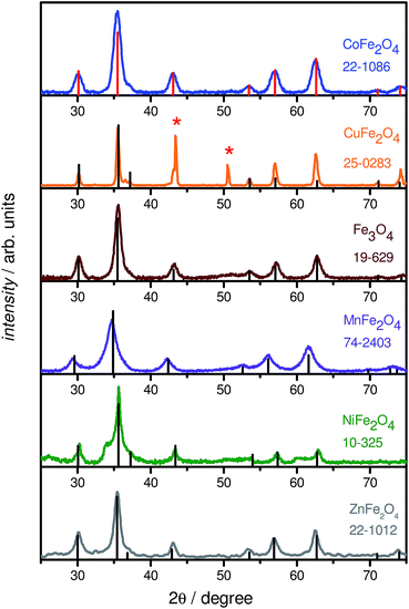
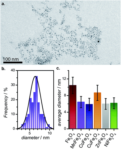
We report a novel synthesis of mixed-metal ferrites in neat PEG (Fig. 1). As may be expected from their PEG coatings, the NPs were highly soluble in water. This synthesis has the advantage of simplicity, using simple reactants and a single-pot protocol. The chemistry is general, and worked with all metal precursors used, yielding phase-pure samples (vide infra). The exception was CuFe2O4, which is also seen to contain elemental Cu in addition to CuFe2O4 (identified in Fig. 2 with asterisks). CuFe2O4 NPs synthesized from Cu(acac)2 showed prominent impurity peaks showing the presence of copper and iron oxides (not shown), which is documented.43 The presence of secondary phases was minimized (but not eliminated) by using CuCl2·2H2O as a copper source, as recommended by Ros and colleagues.44 The size distributions are not quite monodisperse, with ratios of the standard deviation over the mean of approx. 20% (by this metric, a value smaller than 10% would be required for a sample to be deemed monodisperse). It is anticipated that size can be controlled in these systems by varying the ratio of reducing agent to metal precursor. | ||
| Fig. 1 Synthetic scheme for the one-pot synthesis of superparamagnetic, PEG400-coated MFe2O4 (M = Mn, Fe, Co, Ni, Cu, Zn) NPs with sizes ranging from ca. 6 to 10 nm. | ||
This synthesis was inspired by a reductive synthesis of Fe3O4 NPs.30,41 In the initial report,41 Yathindranath et al. describe a reductive step to form the divalent Fe2+ cations necessary for the formation of the spinel structure. In our case, no such reductive step is required as the divalent cation is directly supplied. Nonetheless, the addition of NaBH4 triggers the nucleation of MFe2O4 NPs. We surmise NaBH4 reacts with adventitious water or end groups of the PEG polymer chains to form hydroxyl ions, which form intermediate metal hydroxides (Fe(OH)3 and M(OH)2) that condense and dehydrate to form the oxide, regenerating water. No NPs were obtained in a control experiment setting which omitted the addition of NaBH4 to the reaction mixture.
3.2 Structural characterization
PXRD measurements were performed to determine the phase of MFe2O4 NPs. Fig. 2 shows typical XRD patterns of the various MFe2O4 nanoparticles, along with the corresponding standard line patterns for each ferrite. The XRD analysis revealed that all the samples are spinel cubic in structure (space group: Fd![[3 with combining macron]](https://www.rsc.org/images/entities/char_0033_0304.gif) m), exhibiting six prominent peaks. A slight shift in peak positions for the substituted spinel NPs with respect to unsubstituted Fe3O4 NPs could be noted; this change is well-recorded in literature, and is in agreement with the ionic radii of the divalent cations, indicating a successful incorporation of divalent cations into the lattice.45 In general, the powder X-ray diffractograms of all the MFe2O4 NPs are in excellent agreement with their theoretical counterparts, as can be seen from Fig. 2, the exception being CuFe2O4, which also showed the presence of Cu0 NPs. EDXS analysis also confirmed the formation of stoichiometric MFe2O4 phases, with the M
m), exhibiting six prominent peaks. A slight shift in peak positions for the substituted spinel NPs with respect to unsubstituted Fe3O4 NPs could be noted; this change is well-recorded in literature, and is in agreement with the ionic radii of the divalent cations, indicating a successful incorporation of divalent cations into the lattice.45 In general, the powder X-ray diffractograms of all the MFe2O4 NPs are in excellent agreement with their theoretical counterparts, as can be seen from Fig. 2, the exception being CuFe2O4, which also showed the presence of Cu0 NPs. EDXS analysis also confirmed the formation of stoichiometric MFe2O4 phases, with the M![[thin space (1/6-em)]](https://www.rsc.org/images/entities/char_2009.gif) :
:![[thin space (1/6-em)]](https://www.rsc.org/images/entities/char_2009.gif) Fe ratio being approximately equal to 1
Fe ratio being approximately equal to 1![[thin space (1/6-em)]](https://www.rsc.org/images/entities/char_2009.gif) :
:![[thin space (1/6-em)]](https://www.rsc.org/images/entities/char_2009.gif) 2 for all the five ferrite NPs; the CuFe2O4 NP system, once again, was the slight outlier. As Cu NPs are not expected to be magnetic or only negligibly so,46 the presence of Cu NPs does not greatly impact the following discussion, with the caveat that all values must be taken as lower limits for CuFe2O4.
2 for all the five ferrite NPs; the CuFe2O4 NP system, once again, was the slight outlier. As Cu NPs are not expected to be magnetic or only negligibly so,46 the presence of Cu NPs does not greatly impact the following discussion, with the caveat that all values must be taken as lower limits for CuFe2O4.
The PEGylated MFe2O4 NPs were examined by TEM to assess size and morphology (Fig. 3 and S1†). As can be seen, all the samples contain small spherical NPs (<20 nm in diameter) with comparable size distributions. The reasonable size monodispersity is believed to be controlled by the nucleation and growth of the NP seeds generated upon the rapid addition of NaBH4 to the precursor in PEG medium at high temperatures.
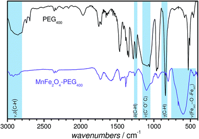
Fig. 4 shows a representative FT-IR spectrum of PEGylated MnFe2O4 NPs superimposed on the spectrum of neat PEG. It is seen that there are several bands that appear in both the spectra, some of which have been highlighted in the figure: (i) the characteristic absorption band at 950 cm−1, associated with the –CH out-of-plane bending vibrations of PEG; (ii) the absorption band at 1240 cm−1, assigned to C–H twisting in PEG; (iii) the C–O–C ether stretching absorption band at 1094 cm−1; (iv) the bands at ∼2800–3000 cm−1, corresponding to –C–H symmetric and asymmetric stretching vibrations; (v) the band around 2910 cm−1, corresponding to –CH2 stretching vibrations. The C–O–C, –CH2 and –CH peaks confirm the tethering of PEG onto the MFe2O4 NP surfaces.47 The FT-IR spectra of the other PEGylated MFe2O4 NPs are shown in Fig. S2.†
3.3 Magnetic characterization
The magnetic properties of the samples were investigated by SQUID magnetometry. For all the magnetic measurements presented here, samples were powdered, and thus the measured magnetic properties represent the average values for an ensemble of randomly oriented nanoparticles. Magnetization vs. magnetic field strength loops were recorded at 310, 300 and 1.9 K (310 K: Fig. 5; 300 and 1.9 K: Fig. S3†) for all the metal ferrite samples. In the M(H) curves, hysteresis is observed at 1.9 K, which is characteristic of ferromagnetic behavior, while anhysteretic loops are seen at the physiological temperature, 310 K. The magnetization of the samples was also examined under FC and ZFC conditions. Combined FC–ZFC plots for PEGylated MFe2O4 NPs are found in Fig. S4.† All NPs showed blocking temperatures (TB, indicating the transition from low-temperature, ferromagnetic NPs to freely fluctuating superparamagnetic NPs at higher temperatures) below room temperature. For all samples, the behavior is typical of superparamagnetism, which is expected for nanoscaled magnetic NPs.45 The exception is CoFe2O4, whose TB is slightly below room temperature. Upon closer inspection, the room-temperature M(H) loop for CoFe2O4 shows a very weak hysteresis. This is consistent with a sample with the majority of NPs in the superparamagnetic state, with a minor component of blocked NPs. The magnetic properties are compiled in Tables 1 and S2.†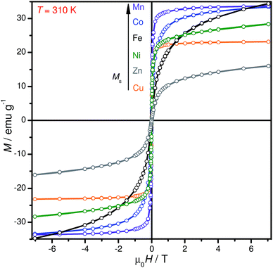 | ||
| Fig. 5 Measured magnetization versus field strength curves for all PEGylated MnFe2O4 NP samples at 310 K. | ||
| Sample | Ms, 310 K (emu g−1) | TB (K) |
|---|---|---|
| MnFe2O4 | 33.7 | 47 |
| Fe3O4 | 34.4 | 150 |
| CoFe2O4 | 33.3 | 280 |
| NiFe2O4 | 28.4 | 150 |
| CuFe2O4 | 23.2 | 61 |
| ZnFe2O4 | 16.0 | 32 |
In general, the Ms values of our PEGylated MFe2O4 NPs were lower than their bulk counterparts: for example, at 300 K, MnFe2O4–PEG400 NPs showed a saturated magnetization Ms of 35.9 emu g−1, which is considerably smaller than the theoretical value of bulk MnFe2O4 material (110 emu g−1),48 but very close to the Ms shown by tetraethylene glycol coated 7 nm MnFe2O4 NPs synthesized by Yang et al. The reduced saturation magnetization of NPs is attributed to the existence of a magnetically ‘dead’ surface layer for each particle in which magnetic moments do not contribute to the magnetization.49 Given that our CuFe2O4 NPs had a non-negligible amount of copper contaminant, it is difficult to compare its magnetic properties with the other uncontaminated PEGylated MFe2O4 NPs, especially since elemental copper is orders of magnitude less magnetic than CuFe2O4.46 A brief discussion on the observed magnetic properties of individual NPs vis-a-vis literature is found in the ESI.†
From the M vs. H curve of CoFe2O4 NPs at 1.9 K, it can be clearly seen that they exhibit an anomalous hysteresis behaviour. These broadened hysteresis loops are often seen in nanocomposite systems with strongly coupled soft and hard magnets; most notably in CoFe2O4 thin films.50,51 Ros and co-workers noted a similar broadened hysteresis loop for their ∼7 nm CoFe2O4 NPs, which they attributed to the presence of a strain inhomogeneity from the surface to the core of the NP, leading to the coexistence of soft and hard magnetic behavior within a single particle.43 The TB for these NPs, at ∼280 K, is also significantly greater than that of the other ferrite NPs; this is expected for CoFe2O4 NPs.45,52 The Co2+ ion – with a d7 configuration – imparts a high magnetocrystalline anisotropy from the presence of spin–orbit coupling. The Ms values recorded were 52.8 emu g−1 at 1.9 K and 33.7 emu g−1 at 300 K.
3.4 Zeta potentials
In order to better understand the physiological stability of MFe2O4–PEG400 NPs, zeta potentials (ζ) were measured post-sonication in distilled water at pH ∼ 7. The recorded values are compiled in Fig. 6a, and are in accordance with literature precedents, such as the work of Feng et al., who found ζ = −21 mV for their (methoxy polyethylene glycol)-coated Fe3O4 NPs.53 It is expected that ζ values for these systems might become even higher in physiological buffer owing to protein corona formation and the associated electrosteric repulsion.54,55 A time-dependent study of the evolution of ζ values for PEGylated Fe3O4 and MnFe2O4 NPs (Fig. 6b) didn't show any drastic changes in the ζ-potential values of these systems over a period of 24 h or more.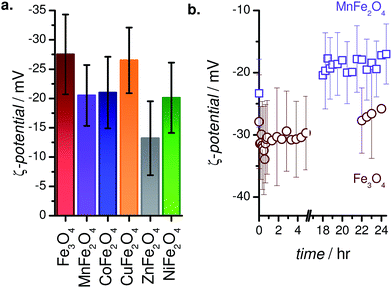 | ||
| Fig. 6 (a) ζ-Potentials of MFe2O4–PEG400 NPs in water (pH 7). (b) Temporal evolution of the ζ-potential of Fe3O4–PEG400 and MnFe2O4–PEG400 NPs in water. | ||
3.5 Magnetic resonance imaging
The dispersed solutions of MFe2O4–PEG400 NPs in water were used in a relaxometric study to determine the T1 and T2 relaxation times, and evaluate their potential as MRI contrast agents. Representative images are show in Fig. 7. As can be seen, contrast increases with concentration (Fig. 7a), while the various MFe2O4 species showed distinct contrast. A sample relaxometric plot for PEGylated MnFe2O4 NPs is shown in Fig. 8, with the relaxation rates R1 (=T1−1) and R2 (=T2−1) plotted as a function of the concentration of the magnetic ions in solution. These same measurements for the other samples are shown in Fig. S5.† The effectiveness of NPs as contrast agent is measured in the form of relaxivity, which represents the reciprocal of the relaxation time per unit concentration of magnetic ions (cf. eqn (2)).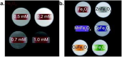 | ||
| Fig. 7 (a) T2-weighted image of Fe3O4 samples in water at various [Fe] concentrations (b) T2-weighted image of MFe2O4 samples in water. | ||
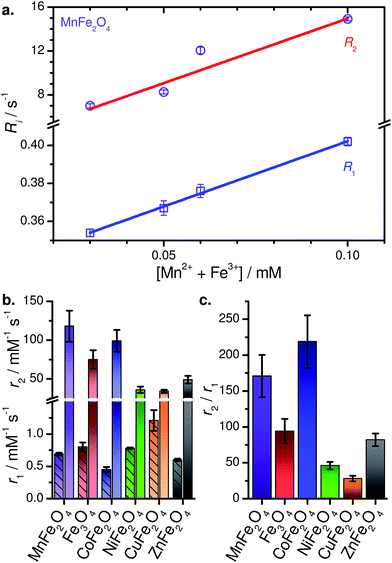 | ||
| Fig. 8 (a) Relaxometric plot for MnFe2O4–PEG400 NPs in water. (b) Compiled relaxivities (r1 below the break with hatched bars, r2 above the break). (c) Compiled r2/r1 ratios. | ||
This is one of the few systematic investigations of the high-field MRI capabilities in a series of MFe2O4, spanning over six compositions. Of the six MFe2O4–PEG400 NPs, MnFe2O4–PEG400 NPs are found to be the most effective T2 contrast agents in aqueous media, with r1 = 0.69 ± 0.02 mM−1 s−1, r2 = 118 ± 20 mM−1 s−1, and r2/r1 = 173. Table 2 lists the r1, r2, and r2/r1 values of the other PEGylated MFe2O4 NPs. CuFe2O4 NPs, laced with elemental copper NPs, show modest contrast-enhancing capabilities which must be considered a lower limit. Interestingly, they show the highest r1 of the series; as such, further investigation of this species for T1-weighted MRI may be warranted. We note that to the best of our knowledge, this is only report of CuFe2O4 NPs used for high-field MRI.
| Labela | Sample | B0 (T) | r1 (mM−1 s−1) | r2 (mM−1 s−1) | r2/r1 | Reference | ||
|---|---|---|---|---|---|---|---|---|
| Core | Coatingb | Size (nm) | ||||||
| a Refers to Fig. 9.b DEG: diethylene glycol; PAA: poly(acrylic acid); CTAB: cetyltrimethylammonium bromide; PMAO: poly(maleic anhydride-alt-1-octadecene); HDA-G2: conjugates of dendritic molecules and 1-hexadecylamine; 1,2-PG: 1,2-propylene glycol; TEG: tetraethylene glycol. | ||||||||
| 1 | Gd2O3 | PEG | 1.3 | 11.7 | 10.4 | 17.2 | 1.7 | Faucher et al.57 |
| 2 | Gd2O3 | DEG | 4.6 | 7 | 4.4 | 28.9 | 6.6 | Bridot et al.58 |
| 3 | CoFe2O4@ZnO | Chitosan | 11.6 | 9.4 | — | 31.8 | — | Venkatesha et al.59 |
| 4 | Mn0.29Fe2.71O4 | PEG8000 | 6.5 | 9 | — | 32.7 | — | Vamvakidis et al.60 |
| Cu | CuFe2O4 | PEG | 8.6 | 9.4 | 1.21(16) | 34(2) | 28(4) | This work |
| Ni | NiFe2O4 | PEG | 6.1 | 9.4 | 0.78(1) | 36(4) | 46(5) | This work |
| Zn | ZnFe2O4 | PEG | 5.9 | 9.4 | 0.60(2) | 49(5) | 82(9) | This work |
| 5 | ZnFe2O4 | Chitosan–liposome | ≤200 | 9.4 | — | 54 | — | Hoque et al.61 |
| 6 | Fe3O4 | HDA-G2 | 10 | 7 | — | 60 | — | Zhao et al.23 |
| 7 | CoFe2O4 | Chitosan | 8.3 | 9.4 | — | 60.9 | — | Venkatesha et al.59 |
| 8 | Mn0.35Fe2.65O4 | (1![[thin space (1/6-em)]](https://www.rsc.org/images/entities/char_2009.gif) : :![[thin space (1/6-em)]](https://www.rsc.org/images/entities/char_2009.gif) 1) 1,2 PG + TEG 1) 1,2 PG + TEG |
6.0 | 9 | — | 64.5 | — | Vamvakidis et al.60 |
| 9 | ZnFe2O4 | PEG | 5 | 9.4 | — | 68 | — | Hoque et al.61 |
| Fe | Fe3O4 | PEG | 10.4 | 9.4 | 0.80(7) | 75(12) | 94(17) | This work |
| 10 | ZnFe2O4 | Chitosan | 4.8 | 9.4 | — | 76 | — | Hoque et al.61 |
| 11 | NiFe2O4 | Chitosan | 3 | 9.4 | 0.348 | 89 | 256 | Hoque et al.62 |
| Co | CoFe2O4 | PEG | 5.8 | 9.4 | 0.45(4) | 99(14) | 219(37) | This work |
| 12 | NaDyF4 | PMAO–PEG | 20.3 | 9.4 | 0.33 | 101 | 306 | Das et al.18 |
| Mn | MnFe2O4 | PEG | 6.4 | 9.4 | 0.69(2) | 118(20) | 171(30) | This work |
| 13 | Fe3O4 | HDA-G2 | 16 | 7 | — | 126 | — | Zhao et al.23 |
| 14 | NaHoF4 | PMAO–PEG | 17 | 9.4 | 0.17 | 130.6 | 781 | Zhang et al.19 |
| 15 | Dy2O3 | Dextran | 70 | 7 | — | 190 | — | Norek et al.63 |
| 16 | Fe3O4 | Maltol | 10.1 | 9.4 | 2.11 | 191 | 90.5 | Clements et al.30 |
| 17 | NiFe2O4 | DMSA | 9.0 | 11.7 | — | 200 | — | Menelaou et al.64 |
| 18 | NaDyF4 | PMAO–PEG | 25 × 35 | 9.4 | 0.50 | 204.4 | 410 | Zhang et al.19 |
| 19 | Fe3O4 octapods | HDA-G2 | 20 | 7 | — | 209 | — | Zhao et al.23 |
| 20 | MnFe2O4 | Succimer | 7.6 | 9.4 | 18.6 | 227.6 | 12.2 | Kim et al.36 |
| 21 | Fe3O4 | Succimer | 6.0 | 9.4 | 11.1 | 255.9 | 23.1 | Kim et al.36 |
| 22 | NiFe2O4 | CTAB | 9.0 | 11.7 | — | 278.9 | — | Menelaou et al.64 |
| 23 | CoFe2O4 | Succimer | 8.0 | 9.4 | 6.3 | 392.5 | 62.3 | Kim et al.36 |
| 24 | Fe3O4 brick-like | Triton X | 64.0 | 7 | 4.3 | 599 | 139 | Worden et al.24 |
| — | GdF3 | PAA | 30–50 | 9.4 | 1.44 | — | — | Ju et al.65 |
It is evident that MnFe2O4, CoFe2O4, and Fe3O4 NPs are better T2 contrast agents compared to NiFe2O4, CuFe2O4, and ZnFe2O4. We generally find that r2 increases with increased saturation magnetization (Fig. S6†), while the r1 values are tightly clustered, with no clear trend with respect to magnetization. As may then be expected, the r2/r1 ratios track the trend seen for r2.
While the r1 and r2 values of our MFe2O4–PEG400 NPs are within range with examples in literature (Fig. 9), we believe further improvements are possible by, e.g., templating directional growth to form morphological variations like octapods,23 bricks,24 or whiskers;25 or subjecting them to controlled aggregation and/or self-assembly, which are known to lead to higher contrasting abilities.56
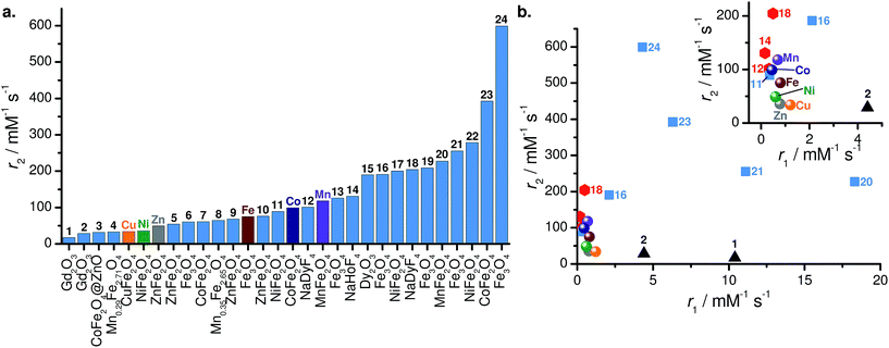 | ||
| Fig. 9 (a) Comparison of r2 values and (b) scatter plot of r1 vs. r2 for various high-field NP contrast agents. Labels refer to Table 2. In panel (b), spheres: data presented in this work; black triangles: Gd2O3 NPs; red hexagons: NaLnF4 NPs; and blue squares: spinel ferrite MFe2O4 NPs. | ||
Most contrast agents were investigated with clinical MRI scanners (1.5–3 T). Well-know examples include the commercially available Ferridex® and Combidex®. Ferridex® has r2 = 120 mM−1 s−1 at a magnetic field of 1.5 T, while the r2/r1 increases from 10.1 to 22 when increasing the magnetic field from 1.5 to 3.0 T.30 Similarly, Combidex® has r2 = 65 mM−1 s−1 at a magnetic field of 1.5 T, with r2/r1 = 6.30
There are few reports of transition metal ferrite NP contrast agents under high-field conditions; this makes a direct one-to-one comparison with our MFe2O4–PEG400 NPs at 9.4 T difficult. This difficulty is exacerbated by significant dependencies of magnetic relaxivities on the magnetic field strength,66 the nature of the solvent (i.e., water vs. plasma vs. buffer), the surface coating,30,39 aggregation,56 and magnetic dynamics.67
A non-exhaustive compilation of relaxivities of various NP contrast agents used at high fields (B0 > 7 T) is presented in Table 2 and Fig. 9. The nanoparticles in this table can be roughly classified as lanthanide oxides57,58,63 and fluorides,65 sodium lanthanide fluorides NaLnF4 (Ln = Ho, Dy),18,19 and spinel ferrites.23,24,30,36,59–61 Upon quick inspection of Fig. 9, it is apparent there is no clear segregation of NP type – or even specific composition – with regards to r2. As an example, our MnFe2O4 (Mn) and CoFe2O4 (Co) NPs are fairly similar in both r1 and r2 to NaHoF4 (13)19 and NaDyF4 (11)18 (see Fig. 9b). The advantage of the NaLnF4 NPs is their paramagnetic nature; unlike superparamagnetic (i.e. electromagnetically coupled spins), they do not saturate in fields up to 9 T and above. However, their magnetization is substantially lower (Ms ≈ 12 emu g−1 at 7 T for 13 (ref. 19)). In this specific comparison, the two effects seem to balance each other. Another striking example is the comparison of Fe3O4–PEG400 (Fe) with maltol-coated Fe3O4 NP (15).30 Both have comparable sizes (10.4 vs. 10.1 nm), yet 15 has a r2 two and a half times that of Fe, despite a lower saturation magnetization (26.8 emu g−1). This discrepancy is attributed to the proximity of water molecules to the magnetic core in 15 due to the small capping ligand.
A compilation of r2/r1 ratios is found in Fig. S7.† As can be seen, the ratios found here compare favourably with state-of-the-art. CoFe2O4 and MnFe2O4 in particular have high values, showing their promise for use as T2 high-field contrast agents.
4 Conclusion
In this study, PEGylated sub-15 nm MFe2O4 (M = Mn, Fe, Co, Ni, Cu, Zn) NPs were synthesized following a novel protocol, with the capping agent (PEG400, a liquid polymer) itself serving as the reaction medium. The NPs were found to be small, fairly monodisperse, and superparamagnetic at room temperature. These NPs were systematically evaluated for high field (B0 = 9.4 T) MRI in vitro. Of the six MFe2O4–PEG400 NP compositions studied, MnFe2O4, CoFe2O4, and Fe3O4 NPs displayed superior T2 contrasting abilities in MRI, with reasonably high r2 values (∼118 mM−1 s−1 for MnFe2O4, ∼98 mM−1 s−1 for CoFe2O4, and ∼75 mM−1 s−1 for Fe3O4) and r2/r1 ratios (∼171 for MnFe2O4, ∼219 for CoFe2O4, and ∼94 for Fe3O4). Given the well-documented biocompatibility of PEG, these transition metal ferrite NP systems deserve to be better investigated as potential contrast agents for dark-field MRI.Author contributions
ST and AB designed the project, AB and EP carried out the synthetic work and physical characterization, BB and BT oversaw MRI measurements, AB, ST and BT contributed to the writing of the manuscript.Conflict of interest
There are no conflicts of interest to declare.Acknowledgements
This work was funded by the Natural Sciences and Engineering Research Council (NSERC) of Canada through a Discovery Grant, an Alberta Innovates Health Solutions CRIO grant, and used infrastructure funded by the Canadian foundation for Innovation (CFI) through a CFI John R. Evans Leaders Fund grant. A. B. thanks the University of Calgary Eyes High Postdoctoral Fellowship Program for funding.References
- E. M. Haacke, R. W. Brown, M. R. Thompson and R. Venkatesan, Magnetic resonance imaging: physical principles and sequence design, Wiley-Liss, New York, 1999, vol. 82 Search PubMed.
- B. M. Dale, M. A. Brown and R. C. Semelka, MRI: basic principles and applications, John Wiley & Sons, 2015 Search PubMed.
- R. H. Hashemi, W. G. Bradley and C. J. Lisanti, MRI: the basics, Lippincott Williams & Wilkins, 2012 Search PubMed.
- G. J. Strijkers, M. Mulder, J. Willem, F. van Tilborg, A. Geralda and K. Nicolay, Anti-Cancer Agents Med. Chem., 2007, 7, 291–305 CrossRef CAS PubMed.
- C. Rydahl, H. S. Thomsen and P. Marckmann, Invest. Radiol., 2008, 43, 141–144 CrossRef CAS PubMed.
- E.-K. Lim, T. Kim, S. Paik, S. Haam, Y.-M. Huh and K. Lee, Chem. Rev., 2015, 115, 327–394 CrossRef CAS PubMed.
- H. B. Na, I. C. Song and T. Hyeon, Adv. Mater., 2009, 21, 2133–2148 CrossRef CAS.
- L. Babes, B. Denizot, G. Tanguy, J. J. Le Jeune and P. Jallet, J. Colloid Interface Sci., 1999, 212, 474–482 CrossRef CAS PubMed.
- B. Blasiak, S. Barnes, T. Foniok, D. Rushford, J. Matyas, D. Ponjevic, W. P. Weglarz, R. Tyson, U. Iqbal, A. Abulrob, G. R. Sutherland, A. Obenaus and B. Tomanek, BMC Med. Imaging, 2013, 13, 20–28 CrossRef PubMed.
- F. Hu and Y. S. Zhao, Nanoscale, 2012, 4, 6235–6243 RSC.
- B. Blasiak, J. Landry, R. Tyson, J. Sharp, U. Iqbal, A. Abulrob, D. Rushford, J. Matyas, D. Ponjevic, G. R. Sutherland, S. Wolfsberger and B. Tomanek, J. Neurosci. Methods, 2014, 226, 132–138 CrossRef PubMed.
- D. Niu, X. Luo, Y. Li, X. Liu, X. Wang and J. Shi, ACS Appl. Mater. Interfaces, 2013, 5, 9942–9948 CAS.
- C. Mainero, T. Benner, A. Radding, A. Van Der Kouwe, R. Jensen, B. Rosen and R. Kinkel, Neurology, 2009, 73, 941–948 CrossRef PubMed.
- R. R. Regatte and M. E. Schweitzer, J. Magn. Reson. Imag., 2007, 25, 262–269 CrossRef PubMed.
- T. Nakada, Brain Dev., 2007, 29, 325–335 CrossRef PubMed.
- P. Stanwell, L. Gluch, D. Clark, B. Tomanek, L. Baker, B. Giuffrè, C. Lean, P. Malycha and C. Mountford, Eur. Radiol., 2005, 15, 1037–1043 CrossRef PubMed.
- B. Blasiak, F. C. van Veggel and B. Tomanek, J. Nanomater., 2013, 2013, 148578 Search PubMed.
- G. K. Das, N. J. Johnson, J. Cramen, B. Blasiak, P. Latta, B. Tomanek and F. Van Veggel, J. Phys. Chem. Lett., 2012, 3, 524–529 CrossRef CAS PubMed.
- X. Zhang, B. Blasiak, A. J. Marenco, S. Trudel, B. Tomanek and F. C. J. M. van Veggel, Chem. Mater., 2016, 28, 3060–3072 CrossRef CAS.
- Y.-w. Jun, Y.-M. Huh, J.-s. Choi, J.-H. Lee, H.-T. Song, K. Kim, S. Yoon, K.-S. Kim, J.-S. Shin, J.-S. Suh and J. Cheon, J. Am. Chem. Soc., 2005, 127, 5732–5733 CrossRef CAS PubMed.
- S. Balasubramaniam, S. Kayandan, Y.-N. Lin, D. F. Kelly, M. J. House, R. C. Woodward, T. G. S. Pierre, J. S. Riffle and R. M. Davis, Langmuir, 2014, 30, 1580–1587 CrossRef CAS PubMed.
- J. Zeng, L. Jing, Y. Hou, M. Jiao, R. Qiao, Q. Jia, C. Liu, F. Fang, H. Lei and M. Gao, Adv. Mater., 2014, 26, 2694–2698 CrossRef CAS PubMed.
- Z. Zhao, Z. Zhou, J. Bao, Z. Wang, J. Hu, X. Chi, K. Ni, R. Wang, X. Chen and Z. Chen, Nat. Commun., 2013, 4, 2266 Search PubMed.
- M. Worden, M. A. Bruckman, M.-H. Kim, N. F. Steinmetz, J. M. Kikkawa, C. LaSpina and T. Hegmann, J. Mater. Chem. B, 2015, 3, 6877–6884 RSC.
- T. Macher, J. Totenhagen, J. Sherwood, Y. Qin, D. Gurler, M. S. Bolding and Y. Bao, Adv. Funct. Mater., 2015, 25, 490–494 CrossRef CAS.
- J. Mohapatra, A. Mitra, H. Tyagi, D. Bahadur and M. Aslam, Nanoscale, 2015, 7, 9174–9184 RSC.
- L. A. Thomas, L. Dekker, M. Kallumadil, P. Southern, M. Wilson, S. P. Nair, Q. A. Pankhurst and I. P. Parkin, J. Mater. Chem., 2009, 19, 6529–6535 RSC.
- C.-L. Liu, Y.-K. Peng, S.-W. Chou, W.-H. Tseng, Y.-J. Tseng, H.-C. Chen, J.-K. Hsiao and P.-T. Chou, Small, 2014, 10, 3962–3969 CrossRef CAS PubMed.
- C. Xu, K. Xu, H. Gu, R. Zheng, H. Liu, X. Zhang, Z. Guo and B. Xu, J. Am. Chem. Soc., 2004, 126, 9938–9939 CrossRef CAS PubMed.
- T. W. Clements, C. Sarsons, C. M. Platnich, A. Banerjee, B. Blasiak, B. Tomanek, K. D. Rinker and S. Trudel, ChemistrySelect, 2016, 1, 1602–1606 CrossRef CAS.
- K. V. Korpany, F. Habib, M. Murugesu and A. S. Blum, Mater. Chem. Phys., 2013, 138, 29–37 CrossRef CAS.
- K. V. Korpany, C. Mottillo, J. Bachelder, S. N. Cross, P. Dong, S. Trudel, T. Friscic and A. S. Blum, Chem. Commun., 2016, 52, 3054–3057 RSC.
- M. Zhang, X. Li, Y. Gong, N. Zhao and X. Zhang, Biomaterials, 2002, 23, 2641–2648 CrossRef CAS PubMed.
- N. A. Alcantar, E. S. Aydil and J. N. Israelachvili, J. Biomed. Mater. Res., 2000, 51, 343–351 CrossRef CAS PubMed.
- J.-H. Lee, Y.-M. Huh, Y.-w. Jun, J.-w. Seo, J.-t. Jang, H.-T. Song, S. Kim, E.-J. Cho, H.-G. Yoon, J.-S. Suh and J. Cheon, Nat. Med., 2007, 13, 95–99 CrossRef CAS PubMed.
- D.-H. Kim, H. Zeng, T. C. Ng and C. S. Brazel, J. Magn. Magn. Mater., 2009, 321, 3899–3904 CrossRef CAS.
- M. Menelaou, Z. Iatridi, I. Tsougos, K. Vasiou, C. Dendrinou-Samara and G. Bokias, Dalton Trans., 2015, 44, 10980–10990 RSC.
- N. Lee and T. Hyeon, Chem. Soc. Rev., 2012, 41, 2575–2589 RSC.
- S. Tong, S. Hou, Z. Zheng, J. Zhou and G. Bao, Nano Lett., 2010, 10, 4607–4613 CrossRef CAS PubMed.
- A. R. West, Basic Solid State Chemistry, John Wiley & Sons, 1999 Search PubMed.
- V. Yathindranath, L. Rebbouh, D. F. Moore, D. W. Miller, J. van Lierop and T. Hegmann, Adv. Funct. Mater., 2011, 21, 1457–1464 CrossRef CAS.
- M. Abràmoff, P. Magalhães and S. Ram, Biophoton. Int., 2004, 11, 36–42 Search PubMed.
- E. Solano, L. Perez-Mirabet, F. Martinez-Julian, R. Guzmán, J. Arbiol, T. Puig, X. Obradors, R. Yañez, A. Pomar, S. Ricart and J. Ros, J. Nanopart. Res., 2012, 14, 1034 CrossRef.
- E. Solano, R. Yáñez, S. Ricart and J. Ros, J. Magn. Magn. Mater., 2015, 382, 380–385 CrossRef CAS.
- A. L. Tiano, G. C. Papaefthymiou, C. S. Lewis, J. Han, C. Zhang, Q. Li, C. Shi, A. M. M. Abeykoon, S. J. L. Billinge, E. Stach, J. Thomas, K. Guerrero, P. Munayco, J. Munayco, R. B. Scorzelli, P. Burnham, A. J. Viescas and S. S. Wong, Chem. Mater., 2015, 27, 3572–3592 CrossRef CAS.
- A. J. Marenco, D. B. Pedersen and S. Trudel, J. Phys. Chem. C, 2016, 120, 7388–7396 CAS.
- Y. Zhang, N. Kohler and M. Zhang, Biomaterials, 2002, 23, 1553–1561 CrossRef CAS PubMed.
- D. Carta, M. F. Casula, A. Falqui, D. Loche, G. Mountjoy, C. Sangregorio and A. Corrias, J. Phys. Chem. C, 2009, 113, 8606–8615 CAS.
- M. Unni, A. M. Uhl, S. Savliwala, B. H. Savitzky, R. Dhavalikar, N. Garraud, D. P. Arnold, L. F. Kourkoutis, J. S. Andrew and C. Rinaldi, ACS Nano, 2017, 11, 2284–2303 CrossRef CAS PubMed.
- S. Xie, J. Cheng, B. Wessels and V. Dravid, Appl. Phys. Lett., 2008, 93, 181901 CrossRef.
- F. Rigato, J. Geshev, V. Skumryev and J. Fontcuberta, J. Appl. Phys., 2009, 106, 113924 CrossRef.
- S. Trudel and R. Hill, Polyhedron, 2007, 26, 1863–1870 CrossRef CAS.
- X. Cao, B. Zhang, F. Zhao and L. Feng, J. Nanomater., 2012, 2012, 1 CrossRef.
- M. Ravichandran, G. Oza, S. Velumani, J. T. Ramirez, F. Garcia-Sierra, N. B. Andrade, M. A. Garza-Navarro, D. I. Garcia-Gutierrez, R. Lara-Estrada and E. Sacristán-Rock, RSC Adv., 2015, 5, 17223–17227 RSC.
- P. Del Pino, B. Pelaz, Q. Zhang, P. Maffre, G. U. Nienhaus and W. J. Parak, Mater. Horiz., 2014, 1, 301–313 RSC.
- S. Singamaneni, V. N. Bliznyuk, C. Binek and E. Y. Tsymbal, J. Mater. Chem., 2011, 21, 16819–16845 RSC.
- L. Faucher, M. Tremblay, J. Lagueux, Y. Gossuin and M. A. Fortin, ACS Appl. Mater. Interfaces, 2012, 4, 4506–4515 CAS.
- J.-L. Bridot, A.-C. Faure, S. Laurent, C. Rivière, C. Billotey, B. Hiba, M. Janier, V. Josserand, J.-L. Coll, L. Vander Elst, R. Muller, S. Roux, P. Perriat and O. Tillement, J. Am. Chem. Soc., 2007, 129, 5076–5084 CrossRef CAS PubMed.
- N. Venkatesha, Y. Qurishi, H. S. Atreya and C. Srivastava, RSC Adv., 2016, 6, 18843–18851 RSC.
- K. Vamvakidis, M. Katsikini, G. Vourlias, M. Angelakeris, E. C. Paloura and C. Dendrinou-Samara, Dalton Trans., 2015, 44, 5396–5406 RSC.
- S. M. Hoque, M. S. Hossain, S. Choudhury, S. Akhter and F. Hyder, Mater. Lett., 2016, 162, 60–63 CrossRef CAS PubMed.
- S. M. Hoque, M. Tariq, S. I. Liba, F. Salehin, Z. H. Mahmood, M. N. I. Khan, K. Chattopadhayay, R. Islam and S. Akhter, Nanotechnology, 2016, 27, 285702 CrossRef PubMed.
- M. Norek, E. Kampert, U. Zeitler and J. A. Peters, J. Am. Chem. Soc., 2008, 130, 5335–5340 CrossRef CAS PubMed.
- M. Menelaou, K. Georgoula, K. Simeonidis and C. Dendrinou-Samara, Dalton Trans., 2014, 43, 3626–3636 RSC.
- Q. Ju, Y. S. Liu, D. T. Tu, H. M. Zhu, R. F. Li and X. Y. Chen, Chem.–Eur. J., 2011, 17, 8549–8554 CrossRef CAS PubMed.
- M. Rohrer, H. Bauer, J. Mintorovitch, M. Requardt and H.-J. Weinmann, Invest. Radiol., 2005, 40, 715–724 CrossRef PubMed.
- P. Caravan, C. T. Farrar, L. Frullano and R. Uppal, Contrast Media Mol. Imaging, 2009, 4, 89–100 CrossRef CAS PubMed.
Footnote |
| † Electronic supplementary information (ESI) available: NP synthesis details; TEM images, magnetic characterization, FTIR spectra, and relaxometric data for all NPs except MnFe2O4. See DOI: 10.1039/c7ra05495e |
| This journal is © The Royal Society of Chemistry 2017 |

