 Open Access Article
Numerical investigation into the vapor-liquid flow in the mixer of a liquid metal Magneto-Hydro-Dynamic system
Peng Lu *a,
Xingwen Zhenga,
Peijie Yanga,
Lulu Fanga and
Hulin Huangb
aJiangsu Province Key Laboratory of Aerospace Power System, Key Laboratory of Thermal Environment and Structure of Ministry of Industry and Information, College of Energy and Power Engineering, Nanjing University of Aeronautics and Astronautics, Nanjing 210016, China. E-mail: plu@nuaa.edu.cn
bCollege of Astronautics, Nanjing University of Aeronautics and Astronautics, Nanjing 210016, China
First published on 19th July 2017
Abstract
Liquid Metal Magneto-Hydro-Dynamic (LMMHD) power generation is a promising technology for waste heat recovery, solar thermal utilization, etc. In this system, a high-temperature liquid metal is mixed with a low-boiling point working fluid, which will evaporate and push the liquid metal to flow through the MHD generator channel. The characteristics of mixing and the vapor–liquid two phase flow will greatly affect the power generation efficiency and effectiveness. This paper firstly proposed a spherical mixer tank for the entire LMMHD system. Then CFD simulation was employed to investigate the above process, with liquid tin as the liquid metal and trifluorotrichloroethane (R113) as the low-boiling point working medium. The findings indicate that an appropriately higher inlet velocity of liquid tin can lead to both higher outlet velocity and larger volume fraction of liquid tin, which is beneficial to MHD power generation. Increasing the initial temperature of liquid tin or inlet velocity of R113 will, on the one hand, elevate the outlet velocity of liquid tin; on the other hand, it will reduce the outlet volume fraction of liquid tin, which was suggested be kept above 20% to avoid the undesirable annular flow. In addition, the inlet velocity of R113 should be kept above 0.05 m s−1; otherwise, liquid tin may flow downwards into its inlet pipeline and cause blockage. The present results will help guide the design, operation and optimization of the mixer, and improve the basic theory of multiphase flow in a LMMHD system.
1. Introduction
Liquid Metal Magneto-Hydro-Dynamic (LMMHD) power generation has been proposed for a variety of heat sources, such as solar and waste heat. This system is based on the extension of Faraday's law of induction to liquid metal and has superior thermodynamic cycle efficiency compared to conventional turbines.1–3 Its thermal efficiency is very close to Carnot cycle efficiency as a result of continuous heating on the expanding vapor (known as the thermodynamic fluid) by the liquid metal (known as the power generation fluid) which acts as an infinite heat source given its high thermal capacity. The vapor expansion can thus be regarded as isothermal, and consequently, contributes to high-efficiency conversion in LMMHD. Besides, a LMMHD system usually has few moving mechanical parts, leading to a quiet operation and a lower manufacturing and maintenance cost.Nowadays, increasingly stringent environmental requirements have aroused widespread interests on LMMHD technology. A. Ishak et al.4 worked on a numerical solution of MHD flow and heat transfer outside a stretching cylinder, aiming to examine the effects of magnetic parameter, Prandtl number and Reynolds number on the velocity and temperature fields. X. Miao et al.5 conducted 3D numerical simulations on a bubble-driven liquid metal flow in a cylinder, with the impact of a steady magnetic field. The comparison between the numerical simulations and the experimental findings showed a good agreement. J. Zhang et al.6,7 numerically investigated the rising motion of a gas bubble in a liquid metal under the influence of a vertical and a horizontal magnetic field successively. The influence of the magnetic fields on properties such as the terminal rising velocity, the rising paths, the bubble shape, and the wake structure was displayed and discussed. M. Goswami et al.8 improved a strategy for a possible correlation between simulation and experimental results with mathematical and physical modelling. X. H. Tian9 numerically simulated bubble motions, including one single bubble rising, two bubbles coalescence and the interaction between bubble and free surface in conductive fluid under different uniform vertical magnetic field intensities. The rising velocity, bubble shape, pressure field, coalescence and breaking time were discussed in details. Q. Y. He et al.10 carried out numerical investigation on MHD flow in 3D rectangular bends at laminar conditions, aiming to reduce the pressure drop in bend corner region caused by electromagnetic coupling in conductive flow, and to search the optimal duct bending. By large eddy simulation, S. Pavlovs et al.11 presented transient distributions of physical fields for turbulent bubbles flow through conductive liquid in the presence of external uniform horizontal or vertical magnetic field. L. Hu et al.12 numerically investigated the performance of a LMMHD system for various external forces with three different working fluids. He found that selecting a liquid metal with low density and high electrical conductivity to work under a long period as well as curbing the shape loss is helpful to improve the power and efficiency. C. N. Kim13 examined the steady-state 3D flows in a LMMHD system which consisted of three sub channels under a uniform magnetic field, with the focus on detailed behaviors of the flow velocity, pressure, current and electric potential.
However, the researches mentioned above are mainly focused on the characteristics of vapor–liquid flow and heat transfer in the presence of magnetic field. The characteristics of mixing and vapor–liquid two phase flow have not drawn sufficient attentions. According to the equation P = σvm2B2, the flow velocity vm affects the generated power P dramatically. In the present paper, we will firstly propose a mixer suitable for LMMHD systems. Based on that, CFD simulation was conducted on the effects of the key inlet and initial parameters, and more importantly, on the characteristics of mixing and vapor–liquid two phase flow in the proposed mixer. The findings will contribute to better understanding of the LMMHD theory and facilitate its commercialized application.
2. Mixer and working medium
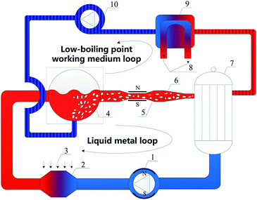
There are two fluids in the LMMHD system, which are the low-boiling point working medium (thermodynamic fluid) and the liquid metal (power generation fluid). The schematic of the LMMHD system along with the mixer we proposed is shown in Fig. 1. This system has two loops, i.e. the liquid metal loop and the low-boiling point working medium loop, including a heater, the mixer, an MHD generator, a nozzle, a separator, a condenser, pumps, etc. Heat energy is added to liquid metal in the heater. The low-boiling point working medium in liquid form enters the mixer, where it contacts and mixes with the high-temperature liquid metal and evaporates; the vapor–liquid two phase flow is then formed inside the mixer. The vapor expands continuously due to the heat from liquid metal, and pushes the fluids through the MHD generator until it is separated from the liquid metal in the separator. After that, the separated vapor is cooled in a condenser, forming the low-boiling point working medium loop; and the liquid metal alone enters the next liquid metal loop. The MHD generator comprises a rectangular channel, one pair opposite sides as electrodes and the other as an insulating wall. The magnetic field is added perpendicular to the vapor–liquid flow direction.In the mixer and the following pipeline, the vapor expands almost isothermally, as the liquid metal acts as a huge heat reservoir due to its large flow rate compared to that of vapor, which contributes to a superior cycle efficiency. That is to say, the mixing of the two fluids, combined with the vapor–liquid two phase flow and heat transfer, plays an important role in the whole system efficiency. The present paper will therefore focus on the above process in the dashed scope marked in Fig. 1. As for the two fluids, we select liquid tin as the liquid metal, and trifluorotrichloroethane (R113) as the low-boiling point working medium. Their physical properties are listed in Tables 1 and 2.
| Physical properties | Liquid tin |
|---|---|
| Molar mass (g mol−1) | 118.71 |
| Melting point (K) | 505 |
| Density (kg m−3) | 6540 |
| Heat capacity (J kg−1 K−1) | 247.82 |
| Viscosity (kg m−1 s−1) | 2.07 × 10⁻³ |
| Heat conductivity (W m−1 K−1) | 33 |
| Physical properties | R113 | R113v |
|---|---|---|
| Molar mass (g mol−1) | 187.376 | 187.376 |
| Boiling point (K) | 321 | — |
| Density (kg m−3) | 1565 | 7.38 |
| Latent heat of vaporization (kJ kg−1) | 146.7 | — |
| Heat capacity (J kg−1 K−1) | 912 | 673 |
| Heat conductivity (W m−1 K−1) | 0.0657 | 0.0778 |
| Viscosity (kg m−1 s−1) | 4.97 × 10⁻⁴ | 1.08 × 10⁻⁵ |
| Enthalpy at standard state (J kmol−1) | −8 × 10⁸ | −6.95 × 10⁸ |
3. Modeling
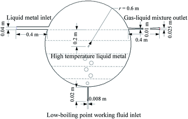
The structural model built by 3D Unigraphics (UG) software is shown in Fig. 2. An adiabatic spherical tank is employed as the mixer. This mixer is designed to hold a large amount of high-temperature liquid tin, acting as a huge heat reservoir. As the quantity of liquid tin is far more than that of R113, it can be considered that R113 expands isothermally, which contributes to superior cycle efficiency. A following de Laval nozzle is applied to speed up and stabilize the vapor–liquid two phase flow.High-temperature liquid metal tin is stored in the spherical mixer tank from the very beginning. Low-boiling point working medium R113 is injected into the tank from the inlet at bottom, while high-temperature liquid tin is supplied from the left-side inlet. R113 is heated and evaporates once it contacts hot liquid tin. The continuous heating on R113 vapor (R113v) and its expansion elevate the pressure inside the mixer and pushes the liquid tin out from the right-side pipeline. Finally, R113 vapor (R113v) carries the liquid tin, in the form of the vapor–liquid two phase flow, passes through MHD generator channel and produces electricity.
In order to numerically investigate the above process, firstly, separation implicit solver and SIMPLE scheme are applied to resolve pressure–velocity coupling equation. Combined with k–ε two-equation turbulent model, standard wall function is applied to the flow in near-wall region. Second-order upwind difference scheme is also employed to improve the computational accuracy by discretizing the physical parameters at the interface of control volume, with the convergence precision within 10−6 of the residual monitor for energy equation. Secondly, conversion between mass source and energy source are compiled by User Defined Function (UDF) and coupled to flow functions. Thirdly, mixture model is selected with inter-phase velocity slip in consideration. Finally, governing equations can be described as follows.
Continuity equation
 | (1) |
Momentum equation
 | (2) |
Energy equation
 | (3) |
Volume fraction equation of the second phase
 | (4) |
Densified grid with size of 2 mm is applied in this work. The inlet boundary condition of the computational domain is set as velocity-inlet, while the outlet condition is pressure-outlet with standard atmospheric pressure. The boundary conditions of pipe wall are set as impermeable and non-slip, with constant wall temperature, adiabatic outside surface, and smooth inside surface. Then assumptions are made as follows: (1) the physical properties of the two fluids are constant; (2) the radiation heat transfer between the two fluids is ignored; (3) there is no heat exchange between the system and the outside surrounding. Gravity acceleration is taken into consideration.
In order to verify the above numerical method, including the multiphase flow model, the turbulence model, and the solution algorithm, we applied it to simulate the research object in ref. 14. The obtained results show good agreement with the reference, as depicted in Fig. 3, which shows the pressure distribution along axial direction at different Reynolds number inside a converging tube. It can be clearly seen that both the variation trend and the values are in excellent agreement, with a maximum error <10%.
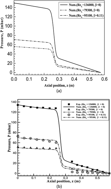 | ||
| Fig. 3 Comparison of the results in the present work and literature.14 (a) The numerical simulation results by the numerical method in the present paper. (b) The results obtained by A. Ahmadpour. | ||
4. Results and discussion
4.1 Analysis on the vapor–liquid two phase flow process
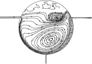
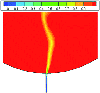
The initial temperature of liquid tin and R113 was 573 K and 310 K, and the inlet velocity of tin and R113 was 0.6 m s−1 and 0.05 m s−1, respectively. Under the above initial conditions, the flow field in the target region is shown in Fig. 4. Due to high density and gravity effect, liquid tin moves downwards along the inner wall after it enters the mixer tank from the left inlet. At the junction of R113 inlet, the two fluids contact and mix, leading to the immediate evaporation of R113. Then R113 vapor (R113v) continues to expand as a result of continuous heating, pushes liquid tin to move ahead, and forms the vapor–liquid two phase flow. It is noticed that at the junction of the right outlet, as the directions of pipeline and vapor–liquid flow are different, part of the fluids flow out of mixer, while the other fluids move upwards and experience a separation process. Because of the difference in the density of liquid tin and R113v, liquid tin falls down onto the bottom, producing series of large anticlockwise circles, which can promote the mixing effect with R113; whereas R113v moves on upwards, forming small clockwise circles.In addition, it should be pointed out that the inlet velocity of R113 should be kept above a certain value, otherwise liquid tin may flow downwards into its inlet pipeline. Fig. 5 displays this phenomenon at the inlet velocity of 0.04 m s−1, from which it can be seen that liquid tin intrudes downwards into the R113 inlet. Since the temperature of liquid R113 is generally lower than 320 K, which is far below the melting point of tin (505 K), liquid tin may solidify and block the inlet pipeline. After numerous numerical simulations, it is suggested that the inlet velocity of R113 should be kept above 0.05 m s−1 to avoid this undesirable phenomenon.
4.2 The influence of inlet velocity of liquid tin
The initial temperature of liquid tin and R113 was 573 K and 310 K, respectively. The inlet velocity of R113 was 0.05 m s−1, while the inlet velocity of liquid tin varied from 0.6 m s−1 to 1.0 m s−1, in order to examine the influence of inlet velocity of liquid tin. The results are presented in Table 3.| vti (m s−1) | 0.6 | 0.8 | 1.0 |
| vto (m s−1) | 1.94 | 2.07 | 2.23 |
| To (K) | 569.8 | 570.6 | 571.0 |
| mRi (kg s−1) | 0.626 | 0.626 | 0.626 |
| mRo (kg s−1) | 0.2676 | 0.2888 | 0.3050 |
| R (%) | 57.25 | 53.87 | 51.28 |
| VFto (%) | 32.71 | 40.70 | 47.24 |
Increasing inlet velocity of liquid tin means more supply of high-temperature liquid metal. As the vapor–liquid two-phase flow velocity inside the mixer increases, the time for heat transfer between the two fluids shortens, which consequently lowers the evaporation rate of R113; consequently, the outlet volume fraction of liquid tin rises. Although the higher outlet velocity and volume fraction of liquid tin will contribute to better power generation in the following MHD generator, it should be pointed out that higher inlet velocity of liquid metal needs to consume more MHD pump power, which in turn reduces the overall efficiency.
4.3 The influence of initial temperature of liquid tin
The inlet velocity of liquid tin and R113 was 0.6 m s−1 and 0.05 m s−1, respectively. The initial temperature of R113 was 310 K, while the initial temperature of liquid tin varied from 573 K to 773 K, in order to examine the influence of initial temperature of liquid tin. The results are listed in Table 4.| Tti (K) | 573 | 673 | 773 |
| vto (m s−1) | 1.94 | 2.14 | 2.28 |
| To (K) | 569.8 | 668.7 | 767.6 |
| mRi (kg s−1) | 0.626 | 0.626 | 0.626 |
| mRo (kg s−1) | 0.2676 | 0.2154 | 0.1751 |
| R (%) | 57.25 | 65.59 | 72.03 |
| VFto (%) | 32.71 | 29.64 | 27.66 |
The rising temperature of liquid metal facilitates the evaporation of R113, leading to a higher evaporation rate. As a result, the carrying capacity of R113v is enhanced and the outlet velocity of liquid tin increases. On the other hand, the volume fraction of R113v at the outlet grows due to the higher evaporation rate, which consequently reduces the outlet volume fraction of liquid tin VFto, as well as the electrical conductivity of the two phase flow. Therefore, although higher initial temperature of liquid tin is desirable on most occasions, we should still pay attention to the key parameter VFto, to prevent it from dropping too much. The reason for this will be explained in details in Section 4.4.
4.4 The influence of inlet velocity of R113
The initial temperature of liquid tin and R113 was 573 K and 310 K, respectively. The inlet velocity of liquid tin was 0.6 m s−1, while the inlet velocity of R113 varied from 0.05 m s−1 to 0.1 m s−1, in order to examine the effect of inlet velocity of R113. Table 5 outlines the results.| vRi (m s−1) | 0.05 | 0.075 | 0.1 |
| vto (m s−1) | 1.94 | 2.47 | 2.96 |
| To (K) | 569.8 | 568.2 | 566.5 |
| mRi (kg s−1) | 0.626 | 0.626 | 0.626 |
| mRo (kg s−1) | 0.2676 | 0.4335 | 0.6100 |
| R (%) | 57.25 | 53.83 | 51.28 |
| VFto (%) | 32.71 | 25.71 | 21.43 |
Higher inlet velocity means more R113 supply, thus more R113 vapor will be produced. As the thermodynamic fluid, its carrying capacity is improved, leading to a higher outlet velocity of liquid tin. Nevertheless, the outlet volume fraction of liquid tin reduces, resulting from the increasing proportion of R113 vapor. Additionally, as the average velocity of R113 in the mixer speeds up, the time for heat transfer between the two fluids shortens, therefore, the evaporation rate of R113 declines.
Similar to Section 4.3, it is noticed that increasing the inlet velocity of R113 will, one the one hand, contribute to a higher outlet velocity of liquid tin, which is beneficial to power generation in the MHD channel; on the other hand, cause a lower outlet volume fraction of liquid tin. Too small volume fraction of liquid tin may result in a large proportion of continuous R113 vapor film between the liquid tin and pipe wall. In other words, the undesirable flow regime of annular flow15,16 may appear, which may cause a poor contact between the liquid tin and the electrodes on the wall in the MHD channel. The poor contact may hinder or even break the electric current loop, and drastically reduce power generation efficiency. It is highly suggested that the outlet volume fraction of liquid tin be controlled above 20% (ref. 17) to avoid the phenomenon above.
4.5 The influence of initial temperature of R113
The inlet velocity of liquid tin and R113 was 0.6 m s−1 and 0.05 m s−1, respectively. The initial temperature of liquid tin was 573 K, while the initial temperature of R113 varied from 280 K to 310 K, in order to examine the influence of initial temperature of R113. The results are outlined in Table 6.| TRi (m s−1) | 280 | 295 | 310 |
| vto (m s−1) | 1.93 | 1.94 | 1.94 |
| To (K) | 569.4 | 569.6 | 569.8 |
| mRi (kg s−1) | 0.626 | 0.626 | 0.626 |
| mRo (kg s−1) | 0.2681 | 0.2678 | 0.2676 |
| R (%) | 57.17 | 57.22 | 57.25 |
| VFto (%) | 32.74 | 32.71 | 32.71 |
Due to a less temperature difference between R113 and liquid tin, higher evaporation rate of R113 is obtained, and the outlet volume fraction of liquid tin declines slightly due to the increasing proportion of R113 vapor. Since more thermodynamic fluid R113 vapor is produced, the outlet velocity of liquid tin increases marginally.
However, it should be pointed out that, given the ambient temperature (normally around 300 K) and boiling point of R113 (321 K), the variation of initial temperature of R113 is set from 280 K to 310 K, which is a rather small range. Therefore the variations of each parameter in Table 6 are minimal. In other words, the influence of initial temperature of R113 can be ignored in practical use.
5. Conclusions
LMMHD power generation is a promising technology for green energy development. The mixing of high-temperature liquid metal and low-boiling point working medium, and the characteristics of the vapor–liquid two phase flow, play an important role in power generation efficiency and effectiveness.A mixer tank designed for LMMHD systems was firstly proposed, with liquid tin as the liquid metal, and trifluorotrichloroethane (R113) as the low-boiling point working medium. Based on that, CFD simulation was employed to reveal the effects of inlet and initial parameters, and more importantly, to understand the characteristics of mixing and vapor–liquid two phase flow. The conclusions are as follows:
• Higher inlet velocity of liquid tin can lead to both higher outlet velocity and more volume fraction of liquid tin, which is beneficial to MHD power generation. However, it needs to consume more pump power, which in turn may reduce the overall efficiency.
• Increasing initial temperature of liquid tin or inlet velocity of R113 can elevate outlet velocity of liquid tin. However, the outlet volume fraction of liquid tin reduces. Excessively low volume fraction of liquid tin may result in an undesirable annular flow regime, which may cause a poor contact between the liquid tin and the electrodes in MHD channel, and consequently reduces power generation efficiency. It is suggested that the outlet volume fraction of liquid tin be controlled above 20%.
• The inlet velocity of R113 should be kept above 0.05 m s−1, otherwise liquid tin may flow downwards into its inlet pipeline, solidify and cause blockage.
Conflict of interest
There are no conflicts of interest to declare.Nomenclature
| B | Strength of the magnetic field |
| Ek | Energy of phase k |
| F | Body force |
| g | Gravitational acceleration |
| J | Current density |
| keff | Effective heat conductivity |
| mRi | Inlet mass flow rate of R113 |
| mRo | Outlet mass flow rate of R113 |
| n | Number of phases |
| p | Pressure |
| P | Output power |
| r | Radius |
| R | Evaporation rate of R113 |
| Rel | Reynolds number of liquids |
| SE | Volumetric heat sources |
| T | Temperature |
| To | Output temperature |
| TRi | Initial temperature of R113 |
| Tti | Initial temperature of liquid tin |
| vdr,k | Drift velocity of phase k |
| vk | Average velocity of phase k |
| vm | Average velocity of mixture |
| vti | Inlet velocity of liquid tin |
| vto | Outlet velocity of liquid tin |
| vRi | Inlet velocity of R113 |
| VFto | Outlet volume fraction of liquid tin |
Symbols
| αk | Volume fraction of phase k |
| β | Air rate |
| σ | Electrical conductivity |
| ρk | Density of phase k |
| ρm | Density of mixture |
| μm | Viscosity of mixture |
Acknowledgements
This work is supported by “National Natural Science Foundation of China” (NO. 11675077); “National Natural Science Foundation of China” (NO. 51506087); “Fundamental Research Funds” (NO. JCKY2013203B003); “China Postdoctoral Science Foundation” (NO. 2015M571747); “the Fundamental Research Funds for the Central Universities” (NO. NJ20160041) and “Foundation of Graduate Innovation Center in NUAA” (NO. kfjj20160210).References
- Y. Peng, in Conference on China Technological Development of Renewable Energy Source, Beijing, 2010, pp. 638–643 Search PubMed.
- C. N. Kim, Fusion Sci. Technol., 2013, 64, 787–799 CAS.
- Y. Liu, X. Z. Shen and K. Chen, Power Equipment, 2002, 5, 45–52. Search PubMed.
- A. Ishak, R. Nazar and I. Pop, Energy Convers. Manage., 2008, 49, 3265–3269 CrossRef.
- X. Miao, D. Lucas, Z. Ren, S. Eckert and G. Gerbeth, Int. J. Multiphase Flow, 2013, 48, 32–45 CrossRef CAS.
- J. Zhang, PhD dissertation, University of Chinese Academy of Sciences, 2014.
- J. Zhang and M. J. Ni, Phys. Fluids, 2014, 26, 102102 CrossRef.
- M. Goswami, S. Kumar and P. Munshi, Flow Meas. Instrum., 2015, 46, 80–86 CrossRef.
- X. H. Tian, Master dissertation, Chongqing University, 2015.
- Q. Y. He, J. C. Feng and H. L. Chen, Fusion Eng. Des., 2016, 109, 1313–1317 CrossRef.
- S. Pavlovs, A. Jakovics, E. Baake and V. Sushkovs, International Journal of Applied Electromagnetics and Mechanics, 2017, 53, S31–S41 CrossRef.
- L. Hu, H. Kobayashi and Y. Okuno, 12th International Energy Conversion Engineering Conference, 2014, pp. 1–8 Search PubMed.
- C. N. Kim, Journal of Mechanical Science and Technology, 2014, 28, 4959–4968 CrossRef.
- A. Ahmadpour, S. M. A. Noori Rahim Abadi and R. Kouhikamali, Int. J. Multiphase Flow, 2016, 79, 31–49 CrossRef CAS.
- Q. Wu, D. L. Schubring and J. J. Sienicki, Nucl. Eng. Des., 2007, 237, 2114–2119 CrossRef CAS.
- R. K. Kapooria, J. Energ. South. Af., 2009, 20, 17–25 Search PubMed.
- G. B. Wallis, One-dimensional two-phase flow, McGraw-Hill, New York, 1969 Search PubMed.
| This journal is © The Royal Society of Chemistry 2017 |

