 Open Access Article
Creative Commons Attribution 3.0 Unported Licence
Characterization of the damping and mechanical properties of a novel (ZnSnO3/PVDF)@PPy nanofibers/EP composite†
Chunmei Zhang‡
a,
Hua Li‡ *ab,
Zhangzhi Zhuoc,
Roberto Dugnanid,
Wenchao Xuea,
Yong Zhoua,
Yujie Chen*a and
Hezhou Liuab
aState Key Laboratory of Metal Matrix Composites, School of Materials Science and Engineering, Shanghai Jiao Tong University, Dongchuan Road No. 800, Shanghai 200240, China. E-mail: lih@sjtu.edu.cn; yujiechen@sjtu.edu.cn
bCollaborative Innovation Center for Advanced Ship and Deep-Sea Exploration, Shanghai Jiao Tong University, China
cWuHu State-owned Factory of Machining, Jiujiang District Wanli Village No. 99, WuHu 241000, China
dUniversity of Michigan-Shanghai Jiao Tong University Joint Institute, China
First published on 26th July 2017
Abstract
In this paper, a novel (ZnSnO3/PVDF)@PPy nanofiber (ZPPs)/EP composite (ZPPE) was prepared and its damping and mechanical properties were investigated. The morphology and structure of the composites were studied using X-ray diffraction (XRD), scanning electron microscopy (SEM), and energy dispersive spectroscopy (EDS). The damping performance was investigated by dynamic mechanical analysis (DMA), and the results showed that for composite ZPPE-60 (i.e., 60% wt ZnSnO3), the storage modulus (E′), loss modulus (E′′) and loss factor (tan![[thin space (1/6-em)]](https://www.rsc.org/images/entities/char_2009.gif) δ) values at 20 °C and 1 Hz increased respectively by about 195%, 655% and 330% compared with the epoxy matrix due to the piezo-damping effect (external mechanical energy–electrical energy–heat energy) and internal friction effect (from fiber–fiber and fiber-matrix friction). The flexural strength and Shore D hardness were also measured to test the composites' mechanical and wear resistance properties. The results suggested that the fabricated ZPPE composites can be used as good structural damping materials.
δ) values at 20 °C and 1 Hz increased respectively by about 195%, 655% and 330% compared with the epoxy matrix due to the piezo-damping effect (external mechanical energy–electrical energy–heat energy) and internal friction effect (from fiber–fiber and fiber-matrix friction). The flexural strength and Shore D hardness were also measured to test the composites' mechanical and wear resistance properties. The results suggested that the fabricated ZPPE composites can be used as good structural damping materials.
1. Introduction
Vibrations and noise generated from automobile, construction, manufacturing industries, etc., negatively affect the design lifetime of engineered structures and could also be harmful to human health and safety. The reduction of vibrations and noise in the aerospace and military fields, etc., has also been extensively researched due to its great strategic implications. Therefore the study of vibration and noise reduction is currently very important both in civil and military fields.1–7Generally, the loss factor (tan![[thin space (1/6-em)]](https://www.rsc.org/images/entities/char_2009.gif) δ) is used to characterize the damping behavior of a material. Materials displaying high tan
δ) is used to characterize the damping behavior of a material. Materials displaying high tan![[thin space (1/6-em)]](https://www.rsc.org/images/entities/char_2009.gif) δ values can dissipate external mechanical vibrations and noise into heat more effectively. Polymers are the most widely used damping materials and, in particular epoxy resins have been extensively utilized in civil and military applications due to their high mechanical strength, low volumetric shrinkage, and good curing characteristics.8–12 Significant damping for epoxy resin is usually limited to the temperature range of Tg ± 10 °C, since external mechanical energy is dissipated into heat mainly via the friction among macromolecule chains near Tg. However, most applications for damping materials require to be used near room temperature hence it is paramount to improve the damping behavior of epoxy polymer near room temperature.
δ values can dissipate external mechanical vibrations and noise into heat more effectively. Polymers are the most widely used damping materials and, in particular epoxy resins have been extensively utilized in civil and military applications due to their high mechanical strength, low volumetric shrinkage, and good curing characteristics.8–12 Significant damping for epoxy resin is usually limited to the temperature range of Tg ± 10 °C, since external mechanical energy is dissipated into heat mainly via the friction among macromolecule chains near Tg. However, most applications for damping materials require to be used near room temperature hence it is paramount to improve the damping behavior of epoxy polymer near room temperature.
Piezo-damping composite is a new kind of damping materials which is composed of the piezoelectric phase, electro-conductive phase, and the polymer matrix. For these class of composites, external mechanical energy can be dissipated via three routes: the viscoelasticity of the polymer matrix itself, internal friction, and the piezo-damping effect. By introducing the piezoelectric phase and conductive phase into the polymer matrix, some of the energy associated with vibration and acoustic noise transforms into electrical energy through the piezoelectric effect of the piezoelectric ceramics. Subsequently, the generated electrical energy can be dissipated into heat as it flows through the composite's resistive phase. Besides, some mechanical energy is dissipated through friction generated by boundary sliding (filler–filler) and interfacial sliding (filler-matrix).13–15 Various piezo-damping materials using epoxy resin or rubber as the polymer matrix have been studied in the past and some promising results have been already reached.16–19 Piezoelectric ceramics with perovskite structure are normally used as the piezoelectric phase in the piezo-damping materials due to their efficient ferroelectric properties. Among them, lead-containing piezoelectric ceramics, such as lead zirconate titanate (PZT), are widely used due to their high piezoelectric coefficient (d33). Nonetheless the fabrication of lead-containing piezoelectric ceramics generates toxic by-products, and the fabrication process is relatively complicated and requires high energy, and generates environmental pollution.20,21 In this paper, we use ZnSnO3/PVDF nanofiber mats as the piezoelectric phase which was prepared by the electrospinning process of a mixture of ZnSnO3 and PVDF. ZnSnO3 is a relatively new kind of lead-free piezoelectric material which has attracted more and more attention and is currently researched for various applications such as nano-generators. There are many merits to ZnSnO3, such as its environmental friendliness, its ability to be synthesized by mild hydrothermal method, and its low-density etc. Most importantly, ZnSnO3 exhibits self-poled behavior under mechanical strain, hence, the electrical poling process is not required.22–24 Poly-vinylidene fluoride (PVDF) is a commonly used commercial piezoelectric polymer due to its excellent flexibility and piezoelectric properties. PVDF exists in at least five different crystalline forms: α, β, γ, δ and ε.25,26 Among them, the β-phase is primarily responsible for the piezoelectric property of PVDF because its piezoelectric activity is based on the dipole orientation within the crystalline phase. Electrospinning is ideally suited for producing piezoelectric nanofibers with the β-phase formation through in situ electric poling and mechanical stretching.27 The electro-spun ZnSnO3/PVDF nanofiber mats possess combined piezoelectricity and could provide abundant fiber-matrix interfacial friction in the composite which is beneficial for the damping performance. Moreover, the mechanical behavior of the prepared epoxy composite is expected to increase through the fiber-reinforced structure. Furthermore, as mentioned above, the ZnSnO3/PVDF nanofiber mats do not need poling process, hence resulting in easy fabrication and energy conservation.
In the previous works, many kinds of conductive filler, such as carbon black, carbon nanotubes, carbon fiber and metal powders have been applied as the conductive phase in piezo-damping composites (ESI†). Alternatively, conducting polymers including polythiophene (PTh), polyaniline (PANI) and polypyrrole (PPy) have been proposed as candidates to replace conductive materials due to their easy fabrication and low cost. In this work, we chose PPy as the conductive phase due to its good conductivity, ease of fabrication, and low density.28,29
In this work, we prepared a new type of piezo-damping (ZnSnO3/PVDF)@PPy nanofibers (ZPPs)/EP composites (ZPPEs) using ZnSnO3/PVDF nanofiber mats as the piezoelectric phase and PPy as the conductive phase. The damping and mechanical properties of the ZPPE composites with different ZnSnO3 loading were investigated and the results were presented later in this article.
2. Experimental
2.1 Materials
Zinc sulfate heptahydrate (ZnSO4·7H2O, AR, 99.5%), sodium stannate tetrahydrate (Na2SnO3·4H2O, AR, 98.0%), acetone (AR, 99.5%), N,N-dimethylformamide (DMF, AR, 99.5%), pyrrole (Py) monomer (AR, 99%), ferric chloride hexahydrate (FeCl3·6H2O, AR, 99%) and ethyl alcohol (AR, 99.7%) were purchased from Sinapharm Chemical Reagent Co., Ltd., China and were used without further purification. The epoxy resin used was E51 and was purchased from Shanghai Resin Factory Co., Ltd., and the curing agent 4,4′-diaminodiphenylmethane (DDM) used was purchased from Shanghai Macklin Biochemical Co., Ltd., China. Poly(vinylidene fluoride-co-hexafluoropropylene) (PVDF–HFP, average Mw ∼ 400![[thin space (1/6-em)]](https://www.rsc.org/images/entities/char_2009.gif) 000, average Mn ∼ 130
000, average Mn ∼ 130![[thin space (1/6-em)]](https://www.rsc.org/images/entities/char_2009.gif) 000, d: 1.77 g ml−1) was purchased from Sigma-Aldrich.
000, d: 1.77 g ml−1) was purchased from Sigma-Aldrich.
2.2 Synthesis of ZnSnO3 powders
Typically the synthesis of single-crystalline ZnSnO3 nanocubes was carried out via hydrothermal method;24 2.88 g (10 mmol) of zinc sulfate heptahydrate (ZnSO4·7H2O) were added into 100 ml of deionized water, and the solution was stirred at room temperature until the ZnSO4·7H2O was dissolved completely. Then, 2.85 g (10 mmol) of sodium stannate solution (Na2SnO3·4H2O) were poured into the ZnSO4·7H2O solution, resulting in a 1![[thin space (1/6-em)]](https://www.rsc.org/images/entities/char_2009.gif) :
:![[thin space (1/6-em)]](https://www.rsc.org/images/entities/char_2009.gif) 1 mol% molar ratio of ZnSO4·7H2O and Na2SnO3·4H2O. The mixed solution was stirred vigorously at 80 °C for five hours. After the reaction, the precipitates were collected by centrifugation and washed with deionized water several times to remove residual ions in the products. The final products were dried at 80 °C overnight for later use.
1 mol% molar ratio of ZnSO4·7H2O and Na2SnO3·4H2O. The mixed solution was stirred vigorously at 80 °C for five hours. After the reaction, the precipitates were collected by centrifugation and washed with deionized water several times to remove residual ions in the products. The final products were dried at 80 °C overnight for later use.
2.3 Fabrication of ZPPE composites
Typically, the PVDF pellets were dissolved into a mixture of acetone and DMF by stirring at 70 °C for 5 hours to get a clear solution. The mass ratio of the PVDF polymer solution was PVDF![[thin space (1/6-em)]](https://www.rsc.org/images/entities/char_2009.gif) :
:![[thin space (1/6-em)]](https://www.rsc.org/images/entities/char_2009.gif) DMF
DMF![[thin space (1/6-em)]](https://www.rsc.org/images/entities/char_2009.gif) :
:![[thin space (1/6-em)]](https://www.rsc.org/images/entities/char_2009.gif) acetone = 0.4
acetone = 0.4![[thin space (1/6-em)]](https://www.rsc.org/images/entities/char_2009.gif) :
:![[thin space (1/6-em)]](https://www.rsc.org/images/entities/char_2009.gif) 1
1![[thin space (1/6-em)]](https://www.rsc.org/images/entities/char_2009.gif) :
:![[thin space (1/6-em)]](https://www.rsc.org/images/entities/char_2009.gif) 1. ZnSnO3 crystals were added to the PVDF solution and stirred vigorously at 70 °C for another 5 hours to get the ZnSnO3/PVDF composite solution used in the electrospinning process.
1. ZnSnO3 crystals were added to the PVDF solution and stirred vigorously at 70 °C for another 5 hours to get the ZnSnO3/PVDF composite solution used in the electrospinning process.
The electrospinning of the ZnSnO3/PVDF mixture was conducted as follow: the distance between the tip of the syringe and the collector was 15 cm; the syringe tip diameter was 23 G (nominal outer diameter: 0.6414 mm, nominal inner diameter: 0.337 mm, nominal wall thickness: 0.1524 mm); the feeding rate of the solution was 1.0 ml h−1 and the electrospinning voltage was 22.5 kV. All the experiments were conducted at room temperature under relatively low humidity (25–40%). The obtained ZnSnO3/PVDF nanofiber mats were placed in an oven at 70 °C overnight to remove residual solvents.
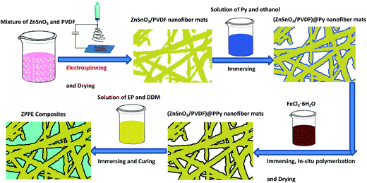
The ZnSnO3/PVDF composite nanofiber mats were cut into 30 × 8 × 2 mm strips and then immersed into a solution composed of Py monomer (0.67 g, 10 mmol) and ethanol (6 ml) for 2 hours. With this process, the surface of the nanofibers was coated with Py monomers as shown schematically in Fig. 1. Afterwards, the mats were taken out of the Py solution and put into a solution of FeCl3·6H2O (6.2 g) and deionized water (6 ml) for 2 hours to complete the in situ polymerization reaction. After washing with deionized water and ethanol several times to remove the unreacted Py monomers and iron ions, the PPy-coated ZnSnO3/PVDF composite nanofibers (ZPPs) were obtained. Subsequently, the ZPP composite nanofiber mats were immersed into a solution of epoxy resin and DDM (acetone used as the solvent) for 2 hours. Then the nanofiber mats were placed under vacuum for 1 hour at room temperature to remove solvents and bubbles, and subsequently they were cured at 80 °C for 2 hours, 120 °C for 2 hours, and 160 °C for 2 hours to get (ZnSnO3/PVDF)@PPy nanofibers/EP composites (ZPPE composites) as shown schematically in Fig. 1. Samples with different amounts of ZnSnO3 (the mass ratio of ZnSnO3/PVDF of 0, 0.2, 0.4, 0.6 and 0.8 referred to as ZPPE-0, ZPPE-20, ZPPE-40, ZPPE-60 and ZPPE-80 respectively) were fabricated and the mass ratio of EP to DDM in the experiment was held constant at 4![[thin space (1/6-em)]](https://www.rsc.org/images/entities/char_2009.gif) :
:![[thin space (1/6-em)]](https://www.rsc.org/images/entities/char_2009.gif) 1.
1.
2.4 Characterization and testing
X-ray diffraction (XRD) spectra were acquired by D/MAX2550/PC using Cu Kα radiation from 8° to 80° at a scan rate of 5° min−1 under 35 kV and 200 mA. The microstructure and the elemental analysis of ZPP composite nanofibers were characterized by field-emission scanning electron microscopy (FE-SEM, Hitachi S-4800) and energy dispersive spectroscopy (EDS, Hitachi S-4800). The quasistatic d33 piezometer (Model/ZJ-3A, China) was used to measure the piezoelectric coefficient of the nanofibers. Dynamic mechanical measurements were performed on Perkin-Elmer DMA 8000 and rectangular prism specimens of 30 × 8 × 2 mm were used for tests. The material property measurements were done in three-point bending mode at the frequency of 1 Hz. The temperature range was from 0 to 160 °C at a heating rate of 5 °C min−1 and the storage modulus, loss modulus, and loss factor were obtained simultaneously. Flexural tests were performed with a three-point bending fixture according to ASTM D-790. The dimensions of the specimens were 50 × 10 × 3 mm, which were subjected to bending with a support span of 20 mm at a constant cross-head speed of 1 mm min−1 on a universal testing machine (BTC-T1-FR020 TN. A50, Zwick, GER). The values were taken from an average of at least five specimens. Shore D hardness was measured according to DIN EN ISO 868 with a portable Shore D measuring instrument with specimens of 50 × 10 × 3 mm, and the reported results were average of at least five measures.3. Results and discussion
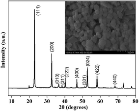
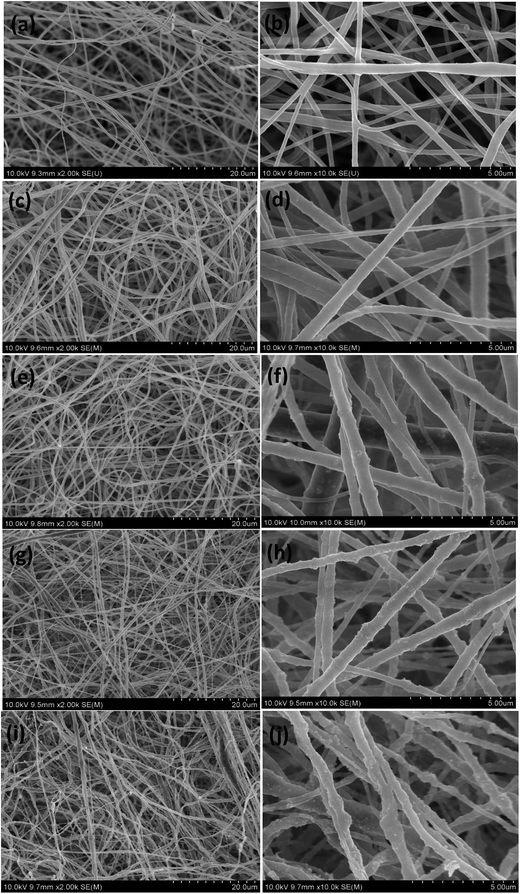
The microscopic surface morphology of hydrothermally synthesized ZnSnO3 powders was studied by SEM as shown in Fig. 2. It can be observed that the prepared ZnSnO3 crystals exhibited a well-defined cubic morphology with similar side length of about 100–200 nm. The X-ray diffraction result shown in Fig. 2 indicated that all of the prepared ZnSnO3 diffraction peaks were in accordance with standard ZnSnO3 displaying the perovskite structure (JCPDS no. 11-0274).22–24 From the XRD pattern, it can also be observed that the ZnSnO3 exhibited perfect crystallinity, and no diffraction peaks from any other impurities were observed.A sample of PVDF was dissolved in a solution of DMF and acetone under vigorous stirring, and various amounts of ZnSnO3 were added into the solution to form a uniform mixture. After the electrospinning and drying process, ZnSnO3/PVDF nanofiber mats were obtained. The morphology of pure PVDF fiber and ZnSnO3/PVDF composite nanofibers with different ZnSnO3 loading were studied by SEM as shown in Fig. 3. In the SEM images, it can be seen that the prepared mats exhibited a three-dimensional fibrous mesh structure, composed of uniform diameter fibers of about 100–500 nm. The ZnSnO3/PVDF nanofibers were randomly oriented, and interconnected voids were observed. The diameters of ZnSnO3/PVDF nanofibers were larger than that of the PVDF fibers due to the aggregation of the ZnSnO3 ceramic particles in the ZnSnO3/PVDF nanofibers. As the content of ZnSnO3 increased, some clusters formed by the accumulation of ZnSnO3 particles could be observed on the fibers' surface of 60 wt% ZnSnO3/PVDF nanofibers (Fig. 3(h)). The stacking of ZnSnO3 particles became more severe as the amount of ZnSnO3 increased to 80 wt% as observed in Fig. 3(j) for 80 wt% ZnSnO3/PVDF nanofibers.
Polypyrrole is a type of electrical conductive polymer widely used on account of its facile fabrication and low cost. The above prepared ZnSnO3/PVDF nanofiber mats were coated with PPy and the surface morphology was observed by SEM. Fig. 4 showed SEM images of ZnSnO3/PVDF composite nano-fibers coated by PPy with different loading ratio of ZnSnO3. Based on these images, it appeared that for all samples, the PPy coated uniformly on the surfaces of the nanofibers. Fig. 4(f) showed that the PPy coating was composed of polypyrrole particles polymerized by pyrrole monomers. The (ZnSnO3/PVDF)@PPy nanofiber mats were constituted by uniform fibers with diameter of approximately 200–800 nm and in general appeared slightly larger than the ZnSnO3/PVDF fibers.
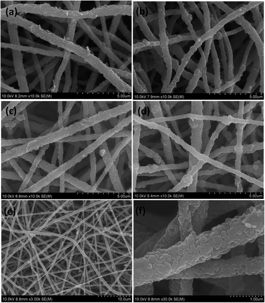 | ||
| Fig. 4 The SEM images of the fabricated (ZnSnO3/PVDF)@PPy nanofibers (ZPPs) with different levels of ZnSnO3: (a) ZPP-20, (b) ZPP-40, (c) ZPP-60, (d) ZPP-80, and (e) and (f) ZPP-60. | ||
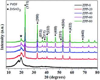
Fig. 5 showed the XRD patterns of PVDF@PPy nanofiber mats and (ZnSnO3/PVDF)@PPy nanofiber mats with different loading of ZnSnO3. The XRD spectra of (ZnSnO3/PVDF)@PPy composite nanofibers exhibited both PVDF peak and the main ZnSnO3 peaks, which confirmed the coexistence of PVDF polymer and ZnSnO3 ceramics in the fabricated composite nanofibers. Furthermore, it was found that, as the content of ZnSnO3 increased, the intensity of the perovskite peaks of ZnSnO3 also gradually increased while the intensity of the peaks of PVDF polymer gradually deceased, similarly to what reported in previous studies.30,31 These results also suggested that the perovskite structure of ZnSnO3 ceramics was undisturbed during the composite manufacturing process with the PVDF polymer and the electrospinning process.
Fig. 6 showed the EDS elemental mapping (C, F, N, O, Sn, Zn) of the fabricated (ZnSnO3/PVDF)@PPy composite nanofibers. From the N element mapping, it was confirmed that the PPy conducting polymer coated uniformly the surface of the ZnSnO3/PVDF nanofibers. The Sn, Zn and O element mapping also proved that at the end of the process the ZnSnO3 ceramic particles were dispersed uniformly in the ZnSnO3/PVDF mixture.
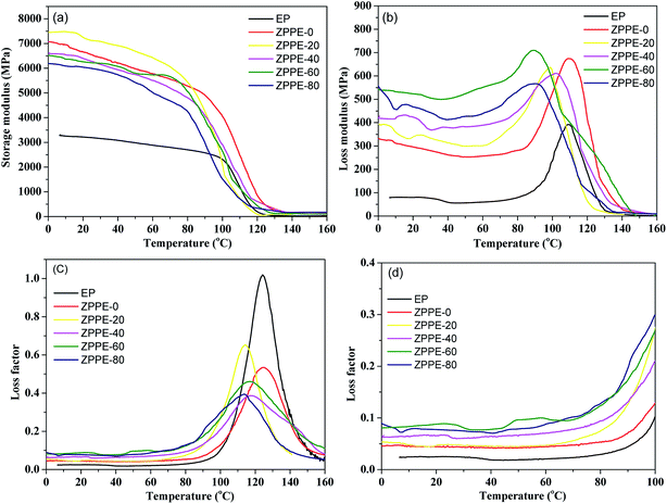
The ZPPEs were fabricated by filling the above prepared (ZnSnO3/PVDF)@PPy nanofiber mats with epoxy resin. The damping properties of the epoxy resin matrix and the fabricated ZPPE composites were investigated by Dynamic Mechanical Analyzer (DMA), and the parameters of the storage modulus (E′), loss modulus (E′′) and loss factors (tan![[thin space (1/6-em)]](https://www.rsc.org/images/entities/char_2009.gif) δ) of materials were recorded simultaneously. Fig. 7(a) showed the epoxy resin's and ZPPEs' E′ values with different ZnSnO3 loadings as a function of temperature. The storage modulus is an important property to assess the load bearing capacity of a material and high E′ value means high stiffness of the material. It was found that the storage modulus of ZPPE composites increased compared with the epoxy matrix. The E′ values were generally in the range of 6–7.5 GPa at room temperature. Table 1 showed that the E′ values of the epoxy matrix, ZPPE-0, ZPPE-20, ZPPE-40, ZPPE-60 and ZPPE-80 at 20 °C were 3.21, 6.66, 7.26, 6.40, 6.26 and 6.04 GPa respectively, which indicated that the ZPPEs had a increase of mechanical performance compared with the epoxy matrix and this may due to the reinforcement effect of the fabric structure of the ZPPs and the high modulus of ZnSnO3 ceramics.
δ) of materials were recorded simultaneously. Fig. 7(a) showed the epoxy resin's and ZPPEs' E′ values with different ZnSnO3 loadings as a function of temperature. The storage modulus is an important property to assess the load bearing capacity of a material and high E′ value means high stiffness of the material. It was found that the storage modulus of ZPPE composites increased compared with the epoxy matrix. The E′ values were generally in the range of 6–7.5 GPa at room temperature. Table 1 showed that the E′ values of the epoxy matrix, ZPPE-0, ZPPE-20, ZPPE-40, ZPPE-60 and ZPPE-80 at 20 °C were 3.21, 6.66, 7.26, 6.40, 6.26 and 6.04 GPa respectively, which indicated that the ZPPEs had a increase of mechanical performance compared with the epoxy matrix and this may due to the reinforcement effect of the fabric structure of the ZPPs and the high modulus of ZnSnO3 ceramics.
| Sample | Storage modulus (E′) (MPa) at 20 °C | Loss modulus (E′′) (MPa) at 20 °C | Loss factor (tan![[thin space (1/6-em)]](https://www.rsc.org/images/entities/char_2009.gif) δ) at 20 °C δ) at 20 °C |
Tg (°C) | Temperature range (°C)/tan![[thin space (1/6-em)]](https://www.rsc.org/images/entities/char_2009.gif) δ > 0.3 (ΔT) δ > 0.3 (ΔT) |
|---|---|---|---|---|---|
| Epoxy resin | 3214.5 | 79.8 | 0.025 | 124.3 | 109.9–139.7 (29.8) |
| ZPPE-0 | 6655.8 | 295.8 | 0.044 | 125.2 | 111.8–137.2 (25.4) |
| ZPPE-20 | 7257.4 | 339.3 | 0.047 | 114.2 | 101.0–125.6 (24.6) |
| ZPPE-40 | 6399.2 | 422.1 | 0.066 | 117.4 | 107.7–130.8 (23.1) |
| ZPPE-60 | 6261.6 | 522.6 | 0.083 | 117.3 | 102.6–135.2 (32.6) |
| ZPPE-80 | 6041.4 | 469.9 | 0.078 | 113.7 | 100.3–121.6 (21.3) |
Fig. 7(b) showed the loss modulus of the epoxy matrix and of the fabricated ZPPE composites as a function of temperature. Loss modulus (E′′) is a measure of the energy dissipated as heat per unit cycle under mechanical deformation and it is a used to characterize the viscosity of a material. It was evident that all the fabricated ZPPEs showed higher E′′ values than the epoxy matrix, which indicated that the fabricated ZPPE composites could dissipate more mechanical vibration and noise into heat energy. Furthermore, as the ZnSnO3 content increased, the E′′ values of the composites increased and reached a maximum value for ZPPE-60 at a content of 60 wt% ZnSnO3. For ZnSnO3 content higher than 60 wt%, E′′ was found to decrease. Table 1 showed that the E′′ values for the epoxy matrix, ZPPE-0, ZPPE-20, ZPPE-40, ZPPE-60 and ZPPE-80 at 20 °C were 0.080, 0.296, 0.339, 0.422, 0.523 and 0.470 GPa respectively. Composite ZPPE-60 displayed the best loss modulus behavior at room temperature and its E′′ value represented an increase of about 655% compared to the epoxy matrix at the same temperature.
The loss factor is defined as the ratio of storage modulus and loss modulus and higher tan![[thin space (1/6-em)]](https://www.rsc.org/images/entities/char_2009.gif) δ values indicate better energy dissipation capability of a material. Normally, the service environment for most engineering damping materials is near room temperature, hence the value of tan
δ values indicate better energy dissipation capability of a material. Normally, the service environment for most engineering damping materials is near room temperature, hence the value of tan![[thin space (1/6-em)]](https://www.rsc.org/images/entities/char_2009.gif) δ should be as high as possible near room temperature. The loss factor values of the epoxy matrix and ZPPEs as a function of temperature at 1 Hz were shown in Fig. 7(c) and (d). It was evident that the loss factors of all ZPPE composites had been enhanced greatly compared with the epoxy matrix in the temperature range of 0–100 °C. This temperature range lied below the Tg, since as shown in Table 1, the glass transition temperature of the epoxy polymer and the ZPPEs was approximately in the range of 113–125 °C. The Tg value in this manuscript was defined by the temperature in the peak of the energy dissipation curves (tan
δ should be as high as possible near room temperature. The loss factor values of the epoxy matrix and ZPPEs as a function of temperature at 1 Hz were shown in Fig. 7(c) and (d). It was evident that the loss factors of all ZPPE composites had been enhanced greatly compared with the epoxy matrix in the temperature range of 0–100 °C. This temperature range lied below the Tg, since as shown in Table 1, the glass transition temperature of the epoxy polymer and the ZPPEs was approximately in the range of 113–125 °C. The Tg value in this manuscript was defined by the temperature in the peak of the energy dissipation curves (tan![[thin space (1/6-em)]](https://www.rsc.org/images/entities/char_2009.gif) δ curves) as reported in other works.34,35 In fiber or nanofiller reinforced composites, there are two possible factors that can affect the Tg of composites. On one hand, the addition of (ZnSnO3/PVDF)@PPy nanofibers can lead to the reduction of Tg by decreasing the crossing-linking density of the epoxy matrix, which was resulted from disturbing the stoichiometric curing reaction between the curing agents and the epoxy matrix. On the other hand, the nitrogen-containing functional groups on the fiber surface can react with the epoxy matrix, thus the mobility of the matrix polymer chains was constrained by the substantial interphase zone around the nanofibers. Moreover, the nanofiber mats can result in higher surface area with more interphase zone in contact with the polymer matrix and thus make the Tg shift to higher temperature. The final effect on Tg will depend on the balance of the two effects, which are influence on reaction conversion and molecular confinement as reported by other works.34–38 The Tg decrease can be attributed to that the reduced degree of cross-linking of the epoxy matrix functioned more. As for ZPPE-0, from the SEM picture in Fig. 3(a) and (b), the nanofiber mats were sparser, thus the cross-linking density was less affected, and the confinement of polymer molecular mobility was more obvious, which lead to a little higher Tg than the epoxy resin. In the temperature range below Tg, the macromolecule chains of epoxy polymer were frozen hence the significant rise of the damping performance was attributed to the piezoelectric damping effect and the friction effect. When ZPPE composite was subjected to external alternating force, some strain energy was transformed into electrical energy via the piezoelectric effect of ZnSnO3/PVDF nanofibers, and then the generated electrical current was dissipated as heat when flowing through the PPy conductive coating on the surface of the nanofibers. Furthermore, friction from fiber boundary sliding (fiber–fiber) and interfacial sliding (fiber-matrix) also dissipated mechanical energy into heat. As shown in Fig. 7(c), it can found that in the glass transition region, the loss factor's peak intensity of all ZPPEs was lower than the one for the epoxy matrix. This occurred because that the introduction of ZPP nanofibers was beneficial to the enhancement of damping performance of ZPPEs near Tg on account of the friction effect. However, most external mechanical energy was mainly dissipated by the constrainedly movement of macromolecule chains under high viscosity system near Tg. For ZPPEs, the ZPP nanofiber mats possessed the main volume content and even the voids were filled with some epoxy polymer, the energy dissipation capability still cannot be improved to the level of pure epoxy resin at the glass transition temperature. As the temperature raised above Tg, the macromolecule chains of polymer absorbed sufficient energy to promote free motion, so the mechanical energy dissipated into heat was greatly reduced and the loss factor sharply decreased.
δ curves) as reported in other works.34,35 In fiber or nanofiller reinforced composites, there are two possible factors that can affect the Tg of composites. On one hand, the addition of (ZnSnO3/PVDF)@PPy nanofibers can lead to the reduction of Tg by decreasing the crossing-linking density of the epoxy matrix, which was resulted from disturbing the stoichiometric curing reaction between the curing agents and the epoxy matrix. On the other hand, the nitrogen-containing functional groups on the fiber surface can react with the epoxy matrix, thus the mobility of the matrix polymer chains was constrained by the substantial interphase zone around the nanofibers. Moreover, the nanofiber mats can result in higher surface area with more interphase zone in contact with the polymer matrix and thus make the Tg shift to higher temperature. The final effect on Tg will depend on the balance of the two effects, which are influence on reaction conversion and molecular confinement as reported by other works.34–38 The Tg decrease can be attributed to that the reduced degree of cross-linking of the epoxy matrix functioned more. As for ZPPE-0, from the SEM picture in Fig. 3(a) and (b), the nanofiber mats were sparser, thus the cross-linking density was less affected, and the confinement of polymer molecular mobility was more obvious, which lead to a little higher Tg than the epoxy resin. In the temperature range below Tg, the macromolecule chains of epoxy polymer were frozen hence the significant rise of the damping performance was attributed to the piezoelectric damping effect and the friction effect. When ZPPE composite was subjected to external alternating force, some strain energy was transformed into electrical energy via the piezoelectric effect of ZnSnO3/PVDF nanofibers, and then the generated electrical current was dissipated as heat when flowing through the PPy conductive coating on the surface of the nanofibers. Furthermore, friction from fiber boundary sliding (fiber–fiber) and interfacial sliding (fiber-matrix) also dissipated mechanical energy into heat. As shown in Fig. 7(c), it can found that in the glass transition region, the loss factor's peak intensity of all ZPPEs was lower than the one for the epoxy matrix. This occurred because that the introduction of ZPP nanofibers was beneficial to the enhancement of damping performance of ZPPEs near Tg on account of the friction effect. However, most external mechanical energy was mainly dissipated by the constrainedly movement of macromolecule chains under high viscosity system near Tg. For ZPPEs, the ZPP nanofiber mats possessed the main volume content and even the voids were filled with some epoxy polymer, the energy dissipation capability still cannot be improved to the level of pure epoxy resin at the glass transition temperature. As the temperature raised above Tg, the macromolecule chains of polymer absorbed sufficient energy to promote free motion, so the mechanical energy dissipated into heat was greatly reduced and the loss factor sharply decreased.
It was also found that the damping properties of the ZPPEs were significantly influenced by the amount of ZnSnO3. As shown in Table 1, the tan![[thin space (1/6-em)]](https://www.rsc.org/images/entities/char_2009.gif) δ values of epoxy matrix, ZPPE-0, ZPPE-20, ZPPE-40, ZPPE-60 and ZPPE-80 at 20 °C were 0.025, 0.044, 0.047, 0.066, 0.083 and 0.078 respectively. As the ZnSnO3 content increased, the values of the loss factor increased correspondingly and rose up to a maximum value for ZPPE-60. As the ZnSnO3 content increased to 80 wt%, the measured loss factor exhibited a marginal drop. This behavior could be explained by the fact that many ZnSnO3 clusters were found to form on the ZnSnO3/PVDF nanofibers' surfaces. This scenario was disadvantageous for the function of the piezo-damping effect, and also it was believed that the ZnSnO3 aggregations hindered the movement of the epoxy macromolecule segments and negatively affected the fiber-matrix friction effect. In conclusion, the ZPPE-60 composite exhibited the best damping behavior and its tan
δ values of epoxy matrix, ZPPE-0, ZPPE-20, ZPPE-40, ZPPE-60 and ZPPE-80 at 20 °C were 0.025, 0.044, 0.047, 0.066, 0.083 and 0.078 respectively. As the ZnSnO3 content increased, the values of the loss factor increased correspondingly and rose up to a maximum value for ZPPE-60. As the ZnSnO3 content increased to 80 wt%, the measured loss factor exhibited a marginal drop. This behavior could be explained by the fact that many ZnSnO3 clusters were found to form on the ZnSnO3/PVDF nanofibers' surfaces. This scenario was disadvantageous for the function of the piezo-damping effect, and also it was believed that the ZnSnO3 aggregations hindered the movement of the epoxy macromolecule segments and negatively affected the fiber-matrix friction effect. In conclusion, the ZPPE-60 composite exhibited the best damping behavior and its tan![[thin space (1/6-em)]](https://www.rsc.org/images/entities/char_2009.gif) δ value was enhanced by approximately 330% compared with the epoxy matrix, indicating a substantial improvement of damping performance for ZPPE composites. A comparison of damping performance with other piezoelectric damping composites were listed in Table S1.† It can be seen that the composite nanofibers showed higher d33 value than some other lead-free piezoelectric ceramics, such as BaTiO3 or ZnO, which was beneficial for the dissipation of external mechanical energy through the piezoelectric damping effect. Moreover, it can also be observed that the ZPPEs exhibited better damping loss factors when compared with some other structural damping composites (ESI†), thus it can be used as good structural damping materials.
δ value was enhanced by approximately 330% compared with the epoxy matrix, indicating a substantial improvement of damping performance for ZPPE composites. A comparison of damping performance with other piezoelectric damping composites were listed in Table S1.† It can be seen that the composite nanofibers showed higher d33 value than some other lead-free piezoelectric ceramics, such as BaTiO3 or ZnO, which was beneficial for the dissipation of external mechanical energy through the piezoelectric damping effect. Moreover, it can also be observed that the ZPPEs exhibited better damping loss factors when compared with some other structural damping composites (ESI†), thus it can be used as good structural damping materials.
The variation curves of flexural strength, flexural modulus and Shore D hardness of ZPPEs with different ZnSnO3 loading were plotted as shown in Fig. 8 and 9 respectively. As shown in Fig. 8, all the ZPPE composites exhibited higher flexural strength than the epoxy resin matrix. The flexural strength increased with increasing ZnSnO3 loading, and reached a maximum for ZPPE-60, and then it was decreased for composite ZPPE-80. A similar trend was also observed for flexural modulus. This may be due to that the fabric structure of ZPP nanofiber mats and the high modulus of ZnSnO3 ceramics generated beneficial effects on the composites' mechanical behavior. For composite ZPPE-80 with a ZnSnO3 loading of 80 wt%, too many aggregates were formed which led to decrease of flexural property due to stress concentration. As for the Shore hardness results shown in Fig. 9, it can be found that all ZPPE composites showed clear enhancement in hardness when compared with epoxy matrix. The difference was significant between ZPPE-20 and ZPPE-0, which was due to the addition of the high modulus ZnSnO3 ceramics, and meanwhile no evident distinction was observed between ZnSnO3 containing ZPPEs. In general, the Shore hardness increased with increasing ZnSnO3 loading. As is well known, conventional hardness is a measure of the resistance of the material to local deformation under nearly static conditions,32 and these results could anticipate a higher wear resistance for ZPPE composites.33
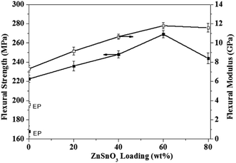 | ||
| Fig. 8 The variation plots of flexural strength and flexural modulus of epoxy resin matrix and the fabricated piezo-damping ZPPE composites with different ZnSnO3 loading. | ||
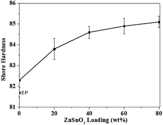 | ||
| Fig. 9 The variation plots of Shore hardness of epoxy resin matrix and the fabricated piezo-damping ZPPE composites. | ||
4. Conclusions
In this work, composite (ZnSnO3/PVDF)@PPy nanofibers (ZPPs)/EP composites (ZPPEs) were fabricated and their damping and mechanical properties were studied. Preliminary results showed that both the damping and mechanical performance of the ZPPEs were greatly enhanced compared with the epoxy matrix. The improved dissipation could be explained by a combination of piezo-damping effect and internal friction. Composite ZPPE-60 exhibited the best damping behavior. When compared with the epoxy matrix, the storage modulus, loss modulus, and loss factor increased by as much as 195%, 655% and 330% at 20 °C respectively under the frequency of 1 Hz. The flexural and wear resistance properties of the ZPPEs were also improved a lot due to the reinforcement effect of the fabric structure of ZPPs. These results suggested that the fabricated ZPPE composites could be used as good structural damping materials.Acknowledgements
This work is supported by the Natural Science Foundation of China (No. 51373096), Basic Research Field of Shanghai Science and Technology Innovation Program (No. 16JC1401500) and Shanghai Sailing Program (No. 16YF1406100). Instrumental Analysis Center of Shanghai Jiao Tong University and National Engineering Research Center for Nanotechnology are gratefully acknowledged for assisting with relevant analyses.Notes and references
- R. Hufenus, L. Gottardo, A. A. Leal, A. Zemp, K. Heutschi, P. Schuetz, V. R. Meyer and M. Heuberger, Mater. Des., 2016, 110, 685–692 CrossRef CAS.
- X. Zhang, L. Liao, N. Ma and H. Wang, Composites, Part A, 2006, 37, 2011–2016 CrossRef.
- U. A. Khashaba, Composites, Part A, 2015, 68, 164–176 CrossRef CAS.
- S. Chen, Q. Wang and T. Wang, Mater. Chem. Phys., 2011, 130, 680–684 CrossRef CAS.
- C. L. Qin, W. M. Cai, J. Cai, D. Y. Tang, J. S. Zhang and M. Qin, Mater. Chem. Phys., 2004, 85, 402–409 CrossRef CAS.
- I. C. Finegan and R. F. Gibson, Compos. Struct., 1999, 44, 89–98 CrossRef.
- R. Chandra, S. P. Singh and K. Gupta, Compos. Struct., 1999, 46, 41–51 CrossRef.
- A. Liu, K. W. Wang and C. E. Bakis, Composites, Part A, 2011, 42, 1748–1755 CrossRef.
- S. Glock, X. X. Zhang, N. J. Kucza, P. Müllner and V. Michaud, Composites, Part A, 2014, 63, 68–75 CrossRef CAS.
- M. J. L. Guen, R. H. Newman, A. Fernyhough and M. P. Staiger, Composites, Part A, 2014, 67, 37–43 CrossRef.
- H. Kishi, M. Kuwata, S. Matsuda, T. Asami and A. Murakami, Compos. Sci. Technol., 2004, 64, 2517–2523 CrossRef CAS.
- T. Wang, S. Chen, Q. Wang and X. Pei, Mater. Des., 2010, 31, 3810–3815 CrossRef CAS.
- D. Carponcin, E. Dantras, G. Michon, J. Dandurand, G. Aridon, F. Levallois, L. Cadiergues and L. Colette, J. Non-Cryst. Solids, 2015, 409, 20–26 CrossRef CAS.
- S. Tian, F. Cui and X. Wang, Mater. Lett., 2008, 62, 3859–3861 CrossRef CAS.
- M. Sunita, H. Gohda, S. Asai and K. Miyasaka, Makromol. Chem., Rapid Commun., 1991, 12, 657–661 CrossRef.
- C. Zhang, J. F. Sheng, C. A. Ma and M. Sumita, Mater. Lett., 2005, 59, 3648–3651 CrossRef CAS.
- Y. Wang, H. Yan, Z. Huang and T. Zhang, Polym.-Plast. Technol. Eng., 2012, 51, 105–110 CrossRef CAS.
- S. Y. Kim, T. Tanimoto, K. Uchino, C. H. Nam, S. Nam and W. I. Lee, Composites, Part A, 2011, 42, 1477–1482 CrossRef.
- M. Hori, T. Aoki, Y. Ohira and S. Yano, Composites, Part A, 2001, 32, 287–290 CrossRef CAS.
- P. K. Panda, J. Mater. Sci., 2009, 44, 5049–5062 CrossRef CAS.
- P. K. Panda and B. Sahoo, Ferroelectrics, 2015, 474, 128–143 CrossRef CAS.
- G. Wang, Y. Xi, H. Xuan, R. Liu, X. Chen and L. Cheng, Nano Energy, 2015, 18, 28–36 CrossRef CAS.
- M. M. Alam, S. K. Ghosh, A. Sultana and D. Mandal, Nanotechnology, 2015, 26, 165403 CrossRef PubMed.
- K. Y. Lee, D. Kim, J. H. Lee, T. Y. Kim, M. K. Gupta and S. W. Kim, Adv. Funct. Mater., 2014, 24, 37–43 CrossRef CAS.
- D. R. Dillon, K. K. Tenneti, C. Y. Li, F. K. Ko, I. Sics and B. S. Hsiao, Polymer, 2006, 47, 1678–1688 CrossRef CAS.
- Y. Xin, X. Qi, H. Tian, C. Guo, X. Li, J. Lin and C. Wang, Mater. Lett., 2016, 164, 136–139 CrossRef CAS.
- H. Yu, T. Huang, M. Lu, M. Mao, Q. Zhang and H. Wang, Nanotechnology, 2013, 24, 405401 CrossRef PubMed.
- Y. Wang, X. Dai, W. Jiang, F. Wu and A. Xie, Mater. Res. Express, 2016, 3, 075023 CrossRef.
- W. Jiang, M. Sun, K. Zhang, X. Dai, Y. Xia, D. Wang, A. Xie and F. Wu, RSC Adv., 2016, 6, 68128–68133 RSC.
- S. H. Ji, J. H. Cho, Y. H. Jeong, J. H. Paik, J. D. Yun and J. S. Yun, Sens. Actuators, A, 2016, 247, 316–322 CrossRef CAS.
- J. S. Yun, C. K. Park, Y. H. Jeong, J. H. Cho, J. H. Paik, S. H. Yoon and K.-R. Hwang, Nanomater. Nanotechnol., 2016, 6, 20, DOI:10.5772/62433.
- W. Brostow and W. Chonkaew, J. Mater. Res., 2007, 22, 2483–2487 CrossRef CAS.
- J. Sanes, F. J. Carrión and M. D. Bermúdez, Wear, 2010, 268, 1295–1302 CrossRef CAS.
- Q. Cheng, J. Bao, J. G. Park, Z. Liang, C. Zhang and B. Wang, Adv. Funct. Mater., 2009, 19, 3219–3225 CrossRef CAS.
- L.-C. Tang, Y.-J. Wan, D. Yan, Y.-B. Pei, L. Zhao, Y.-B. Li, L.-B. Wu, J.-X. Jiang and G.-Q. Lai, Carbon, 2013, 60, 16–27 CrossRef CAS.
- S. Wang, M. Tambraparni, J. Qiu, J. Tipton and D. Dean, Macromolecules, 2009, 42, 5251–5255 CrossRef CAS.
- X.-J. Shen, X.-Q. Pei, S.-Y. Fu and K. Friedrich, Polymer, 2013, 54, 1234–1242 CrossRef CAS.
- T. Ramanathan, A. A. Abdala, S. Stankovich, D. A. Dikin, M. Herrera-Alonso, R. D. Piner, D. H. Adamson, H. C. Schniepp, X. Chen, R. S. Ruoff, S. T. Nguyen, I. A. Aksay, R. K. Prud’Homme and L. C. Brinson, Nat. Nanotechnol., 2008, 3, 327–331 CrossRef CAS PubMed.
Footnotes |
| † Electronic supplementary information (ESI) available. See DOI: 10.1039/c7ra06328h |
| ‡ These authors contributed equally to this work. |
| This journal is © The Royal Society of Chemistry 2017 |

