 Open Access Article
Creative Commons Attribution 3.0 Unported Licence
A dual-functional NaLuF4:Yb3+/Er3+ material for enhancing photon harvesting in dye-sensitized solar cells
Haiyong Guo,
Zhen Hu,
Li Zhao *,
Li Wan,
Yadan Wu and
Shimin Wang*
Hubei Collaborative Innovation Center for Advanced Organic Chemical Materials, Key Laboratory for the Green Preparation and Application of Functional Materials, Ministry of Education, Hubei Key Laboratory of Polymer Materials, Faculty of Materials Science and Engineering, Hubei University, Wuhan 430062, P. R. China. E-mail: zhaoli7376@163.com; shiminwang@126.com
First published on 7th August 2017
Abstract
A new strategy to improve the efficiency of dye-sensitized solar cells by using the external near-infrared light harvesting and light-scattering dual-functional upconversion (UC) material NaLuF4:Yb3+/Er3+ is proposed. The photoluminescence spectra of NaLuF4:Yb3+/Er3+ showed the emission of green and red light, and these luminescence bands coincided well with the absorption wavelength of N719 dye. A small amount of UC material could serve as a good scattering material in photoelectrodes. The photoelectric conversion efficiency reaches 7.58% at a concentration of 5 wt% of UC (weight ratio of UC to TiO2), which is 27.18% higher than that of P25 photoanode (5.96%) with similar thickness. This finding may be attributed to the UC luminescence and light scattering properties of the UC material.
Introduction
Solar energy, an inexhaustible and clean energy source, has been considered as a replacement of non-renewable fossil energy. Dye-sensitized solar cells (DSSCs), which were first reported by Michael Grätzel in 1991,1 attract considerable attention because of their low cost, possible use in fabricating flexible devices, and relatively good efficiency in photovoltaic conversion of solar energy.2–6 A high power conversion efficiency (η) of 14.3% for DSSCs was achieved by using an alkoxysilyl-anchor dye and a carboxy-anchor organic dye.7 A sandwich-structured DSSC consists of a transparent conducting oxide glass, such as fluorine-doped tin oxide (FTO) glass; a dye-adsorbed nanocrystalline semiconductor film (most commonly TiO2); a platinum-coated counter electrode; and an electrolyte containing the I−/I3− redox couple. A current is generated when a dye molecule (usually N719) absorbs a photon, enters an excited electronic state, and injects an electron into the conduction band of the metal oxide photoanode. The circuit is completed when the dye is regenerated through electron transfer by a redox system. The electrolyte system is reduced at the counter electrode. Most contemporary research has conducted in-depth related studies on different aspects, such as various morphologies of TiO2,8–10 combining noble metal nanoparticle composite materials,11–13 and designing and synthesizing new dyes.7,14 Forty-six percent of the total solar energy delivered in the infrared (IR) region (>800 nm)15 is in the solar spectrum. However, the absorption range of DSSC electrode with N719 dye as a sensitizer is mainly in the visible region (a maximum absorption range of the solar spectrum is 300–800 nm (ref. 16)), and the absorption of IR light utilization rate of sunlight is low, thereby restricting the power conversion efficiency of DSSC to a certain extent.An advanced research hotspot improves the absorption of ultraviolet and IR spectrum in DSSCs. Rare earth ions have abundant f-orbital configurations and can exhibit sharp fluorescent emissions via intra-4f or 4f–5d transitions. Thus, the ions can absorb low-energy IR light and then emit high-energy visible light in a process called upconversion.17 Furthermore, the ions can broaden the range of spectral response and increase the utilization rate of light in solar cells.18–20 An efficient and stable fluorescent material consists of a host, a sensitizer and an activator. NaREF4 (RE = rare earth), an important host rare earth fluoride material, has received increasing attention due to its low phonon energy, high chemical and thermal durability, and high efficiency.21–23 Moreover, Yb3+, which is an excellent sensitizer for the activators, has a high and broad absorption band. Er3+ as an activator is the most efficient rare earth ion because of its versatile energy levels in the IR region. The use of NaREF4:Yb3+/Er3+ (UC) as a fluoride material is an emerging technique that can increase the efficiency of solar cells. The use of UC (e.g., NaYF4:Yb3+, Er3+) in DSSCs has recently been reported to enhance near-infrared (NIR) response. Chunze Yuan et al.24 explored the use of colloidal UC nanocrystals as an energy relay material for photovoltaic devices and found that the UC nanocrystals of small size can serve as a scattering material to increase the light absorption capability of cells. Kim et al.25 demonstrated enhanced efficiency from 9.02% of reference DSSCs to 10.76% by upconverting β-NaYF4:Yb3+/Er3+ phosphor microcrystals as an additional phosphor-reflecting film. β-NaLuF4 is a very excellent upconversion material,26,27 and not yet reported in solar cells.
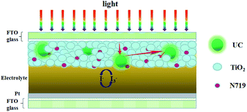
Dual-functional material NaLuF4:Yb3+/Er3+ microcrystals were synthesized in this work, and these microcrystals possess UC luminescence and light scattering properties. This study introduced the above-mentioned material into the TiO2 layer of the photoanode in a DSSC device (Scheme 1) for the first time and obtained an efficiency of 7.58%. This study is expected to lead to a viable strategy for widening the sunlight harvesting range of DSSCs.
Experimental
Materials
Lu(NO3)3·H2O (99.99%), Yb(NO3)3·5H2O (99.9%), Er(NO3)3·5H2O (99.9%), diethylenetriaminepentaacetic acid (DTPA, AR 99%), titanium tetrachloride (TiCl4, AR 99.0%) were all obtained from Aladdin Industrial. Ethanol (AR 99.7%), sodium hydroxide (NaOH, AR 99.0%), sodium fluoride (NaF, AR 98.0%), aqueous ammonia (NH3·H2O, AR 28%) were purchased from Sinopharm Chemical Reagent Co., Ltd., China. TiO2 (particle size: 25 nm, Degussa, Germany), N719 dye (Solaronix S.A., Lausanne, Switzerland), LiI (Sigma-Aldrich Corp., St. Louis, MO, USA), I2 (Sigma-Aldrich Corp., St. Louis, MO, USA), 1-propyl-3-methylimidazolium iodide (Suzhou Zhongsheng Chemical Co., Ltd., Suzhou, China).Syntheses of NaLuF4:Yb3+/Er3+
NaLuF4:Yb3+/Er3+ was synthesized by using the co-precipitation (CPP) method at room temperature. First, Lu(NO3)3·H2O (3.2 mmol), Yb(NO3)3·5H2O (0.72 mmol), Er(NO3)3·5H2O (0.08 mmol) were dissolved in 20 ml of deionized water, DTPA (4.0 mmol) and NaOH (2.0 mmol) were dissolved in 20 ml of deionized water, and NaF (0.05 mol) was dissolved in 60 ml of deionized water. Then, the rare earth solutions and DTPA solutions were added into a container, mixed fully, and then rapidly transferred into NaF solutions with drastic stirring for 2 h. The pH value was adjusted to 7 by adding aqueous ammonia. The precipitates were centrifuged several times, washed with distilled water and ethanol several times to remove the ionic remnants, dried at 80 °C for 12 h, and then calcined at 450 °C for 2 h in air.Fabrication of DSSCs
TiO2 powders (3 g, Degussa P25) and rare earth UC materials were milled with ethanol by using a planetary ball mill for up to 12 h. The compound paste was prepared as follows: ethyl cellulose and terpineol were added to the ethanol solution of the TiO2/UC, and then ethanol was removed from the solution by using a rotary evaporator to obtain a viscous paste. To form the P25/UC composite electrode, paste was deposited onto FTO conducting glass by using the doctor blade technique and was gradually heated to 500 °C for 30 min through a programmed sintering process. After cooling, the paste was immersed in a 0.42 M TiCl4 aqueous solution at 70 °C for 30 min and then sintered at 500 °C for 30 min. The films were subsequently immersed in a 0.5 mM N719 ruthenium dye ethanol solution at room temperature for 24 h. The solar cell was assembled in a typical sandwich-type cell with Pt-coated FTO counter electrode and electrolyte (0.3 M LiI, 0.05 M I2, 0.6 M 1-propyl-3-methylimidazolium iodide and 0.5 M tert-butylpyridine in dry acetonitrile). The active area of a DSSC device exposed to light was 0.16 cm2.Characterization and measurements
Obtained samples were characterized by X-ray diffraction (XRD, Bruker D8A25, Cu Kα, λ = 1.5406 Å) from 10° to 70° to determine phase structures. The morphology and thickness were observed by using scanning electron microscopy (SEM, JSM-5610LV, JEOL). Transmission electron microscopy (TEM, JEM-100SX, JEOL) analyses were conducted with an electron microscope. UV-vis spectrometer (UV-3600, Shimadzu Corp., Tokyo, Japan) was used for absorption measurements and diffusing reflectance spectroscopy (DRS) of the as-prepared samples. BaSO4 was used as a reflectance standard in a UV-vis diffuse reflectance experiment. The UC luminescence was tested by a fluorescence spectrophotometer (RF-6000 Shimadzu Corp., Tokyo, Japan) under excitation by a laser diode (5 W) at 980 nm.The photocurrent–voltage (J–V) characteristic curves of the DSSCs were measured using an IM6 electrochemical analyzer (Zahner Elektrik, Germany) with a scan rate of 0.1 V s−1 under one sun AM 1.5 G (100 mW cm−2) illumination with a solar simulator (Newport 91160). Electrochemical impedance spectroscopy (EIS) measurements were recorded using an electrochemical workstation (IM6, Germany) under one sun illumination. The frequency range was explored from 0.1 Hz to 100 kHz, and the applied bias voltage and ac amplitude were set at an open-circuit voltage of the DSSCs and 10 mV, respectively.
Results and discussion
Phase structure and morphology characterization
The crystal and crystal phase form of the product were first detected by XRD, as shown in Fig. 1, and the stronger diffraction peaks that appeared at 17.3°, 30.1°, 31.2°, 43.9°, and 54.1° can be attributed to the (100), (110), (101), (201), and (211) planes of the hexagonal NaLuF4:Yb3+/Er3+, respectively. The peak positions of NaLuF4:Yb3+/Er3+ shifted to a low 2θ compared with the reported values of β-NaLuF4 (JCPDS no. 27-0726) (Fig. 1b) due to the intercalation of Yb3+ and Er3+ into the NaLuF4 crystal. The ionic radius of Yb3+ (0.99 Å) and Er3+ (1.00 Å) was larger than that of Lu3+ (0.98 Å); thus, Yb3+ and Er3+ replaced Lu3+ in the lattice, unit cell becomes larger, so the diffraction angle will decrease.28,29 In addition, the diffraction peaks were sharp, thereby suggesting that the prepared samples were highly crystalline. Furthermore, none of impurity peaks were observed, indicating the high purity of the final product, which is the key factor for UC fluorescing.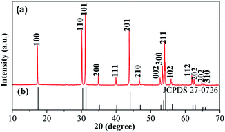 | ||
| Fig. 1 (a) XRD patterns of the as-prepared NaLuF4:Yb3+/Er3+ sample; (b) standard data of hexagonal β-NaLuF4 (JCPDS 27-0726). | ||
The as-prepared NaLuF4:Yb3+/Er3+ sample of the structure and morphology of the product were observed through SEM and TEM. The SEM image (Fig. 2A and B) clearly indicates that the sizes of the UC materials with a smooth surface are in the range of 200–300 nm. Fig. 2C and D indicate the TEM image of the as-prepared UC materials, which further confirms that the as-prepared samples have an average diameter and a smooth surface relatively. Fig. 2E shows the cross-section image of the composite film with a thickness of approximately 24 μm, and the UC material was equally embedded in the composite TiO2 layer. From EDX spectrum (Fig. 2F), peaks of host (Lu) and dopant (Er and Yb) are detected for NaLuF4:Yb3+/Er3+, revealing the presence of Er and Yb atoms with a molar ratio of about 4![[thin space (1/6-em)]](https://www.rsc.org/images/entities/char_2009.gif) :
:![[thin space (1/6-em)]](https://www.rsc.org/images/entities/char_2009.gif) 16
16![[thin space (1/6-em)]](https://www.rsc.org/images/entities/char_2009.gif) :
:![[thin space (1/6-em)]](https://www.rsc.org/images/entities/char_2009.gif) 80 to Lu atoms, which accords with the molar ratio of reactant (2
80 to Lu atoms, which accords with the molar ratio of reactant (2![[thin space (1/6-em)]](https://www.rsc.org/images/entities/char_2009.gif) :
:![[thin space (1/6-em)]](https://www.rsc.org/images/entities/char_2009.gif) 18
18![[thin space (1/6-em)]](https://www.rsc.org/images/entities/char_2009.gif) :
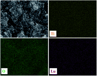
:![[thin space (1/6-em)]](https://www.rsc.org/images/entities/char_2009.gif) 80), roughly. The chemical mapping of the elements appeared in the EDX is shown in Fig. 3; the Ti, O, and Lu elements are evidently distributed homogeneously in the film.
80), roughly. The chemical mapping of the elements appeared in the EDX is shown in Fig. 3; the Ti, O, and Lu elements are evidently distributed homogeneously in the film.
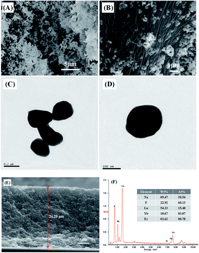 | ||
| Fig. 2 (A, B) SEM and (C, D) TEM images of the as-prepared NaLuF4:Yb3+/Er3+ sample; (E) cross-section image of the composite film; (F) EDX spectrum of NaLuF4:Yb3+/Er3+ sample. | ||
UC fluorescence
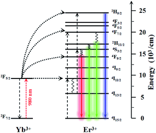
The photoluminescence spectra of the as-prepared NaLuF4:Yb3+/Er3+ excited with a λ = 980 nm laser are shown in Fig. 4. The centered emissions 407, 520, 540, and 654 nm originated from 2H9/2 → 4I15/2, 2H11/2 → 4I15/2, 4S3/2 → 4I15/2, and 4F9/2 → 4I15/2 of Er3+, respectively. In the case of Er3+, the most important excitation path is 4I15/2 → 2I11/2 → 4F7/2, which requires two energy-transfer processes from Yb3+. The subsequent multiphoton relaxation populates the emitting 2H11/2 and 4S3/2 states, and the dominant green 2H11/2 → 4I15/2 and 4S3/2 → 4I15/2 emissions occur. Alternatively, the electrons can further relax and populate 2H9/2 and 4F9/2 levels, thereby resulting in the occurrence of the blue 2H9/2 → 4I15/2 and red 4F9/2 → 4I15/2 emissions. The mechanism responsible for the UC fluorescence of NaLuF4:Yb3+/Er3+ is shown in Scheme 2. The luminescence bands coincide perfectly with the absorption wavelength of N719 dye, thereby indicating that the NIR light can be indirectly absorbed by N719 dye through the UC process. In other words, the incorporation of this UC material composite in DSSCs can feasibly enhance sunlight harvesting in the NIR region. Since the light response region extends from the visible light to the infrared region, the light absorption is enhanced and is therefore considered to improve the photoelectric conversion performance of the DSSC device.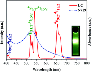 | ||
| Fig. 4 UC photoluminescence spectrum of NaLuF4:Yb3+/Er3+ and UV-vis absorption spectra of N719. The inset shows the photograph of sample under 980 nm laser. | ||
UV-vis spectral characterization of photoanodes
To investigate the light-scattering ability of NaLuF4:Yb3+/Er3+ UC material, we performed UV-vis DRS of photoanodes over the wavelength range of 350–850 nm as shown in Fig. 5a. In the spectral range of 400–800 nm, the composite photoanodes exhibited higher diffuse reflectance than P25. The UV-vis absorption spectra of photoanodes in Fig. 5b indicates that the photoelectrodes doped with UC increased the absorption of light in 550–1200 nm. According to Mie theory,30 the particles are larger, and the UC materials exhibit effective scattering with a micro–nano size and can act as light scattering centers. On the one hand, UC materials increase the optical path length of the incident light via light scattering. On the other hand, UC materials convert the IR light into visible light and broaden the spectral response region. On the basis of these results (Scheme 1), doping with UC will enhance the photocurrent density in the DSSCs.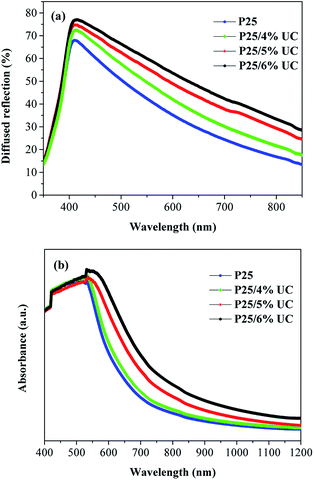 | ||
| Fig. 5 (a) UV-vis diffuse reflectance and (b) UV-vis absorption spectra of photoanodes with increasing amount of NaLuF4:Yb3+/Er3+. | ||
Photovoltaic performances of DSSCs
The J–V performance of DSSCs the AM 1.5 sunlight illumination (100 mW cm−2) is shown in Fig. 6. The photovoltaic characteristics of these DSSCs, such as short-circuit current density (Jsc), open-circuit voltage (Voc), fill factor (FF), and overall light conversion efficiency (η) determined from these measured J–V curves, are summarized in Table 1. With the increase in UC content, Voc increased from 0.725 V to 0.765 V, while Jsc and η increased and then decreased, the highest Jsc achieved 16.42 mA cm−2. The highest photoelectric conversion efficiency of 7.58% was achieved at concentration 5 wt% of UC, which is 27.18% higher than that of P25 photoanode (5.96%) with the same thickness. This improvement can be attributed to two reasons. First, the light spectral response range was broadened through UC by doping a small amount of UC material into the TiO2 films. This electrode has more intense absorption in the NIR region compared with the P25 electrode, thereby greatly increasing the utilization rate of solar energy. Second, the enhanced Jsc is ascribed to the enhanced light harvesting. Therefore, when there is a small amount of UC, the Jsc and η values of the DSSC increase.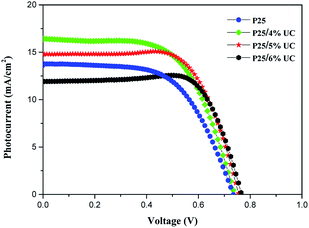 | ||
| Fig. 6 J–V curves of DSSCs with increasing amount of NaLuF4:Yb3+/Er3+ under simulated AM 1.5 G light. | ||
| Samples | Jsc (mA cm−2) | Voc (V) | FF | η (%) |
|---|---|---|---|---|
| P25 | 13.78 | 0.725 | 0.597 | 5.96 |
| P25/4% UC | 16.42 | 0.735 | 0.611 | 7.38 |
| P25/5% UC | 14.82 | 0.755 | 0.677 | 7.58 |
| P25/6% UC | 11.94 | 0.765 | 0.753 | 6.88 |
EIS was performed to understand the electron transfer process of DSSCs. Fig. 7a shows the EIS Nyquist plots of different devices and equivalent circuit. The impedance at low frequency (0.1–1 Hz) generally refers to the Nernst diffusion process of I−/I3− in the electrolyte. The small semicircle at high frequency (1–100 kHz) is related to the electron transfer resistance (Rct) at the Pt|I−/I3− electrolyte, and the large semicircle at medium frequency (1 Hz to 1 kHz) corresponds to the transport resistance (Rw) of photoinduced electron at the TiO2|dye|I−/I3− electrolyte interface. Rs is ascribed to the sheet resistance of FTO and the electrical contact resistance between the FTO|TiO2 film.31,32 The EIS data were fitted to the corresponding equivalent circuit model by using ZSimpWin software, and the Rs, Rct, and Rw data are shown in Table 2. Rs and Rct are similar, and Rw increases from 22.74 Ω of P25 photoanode to 31.33 Ω of composite photoanode at concentration 5 wt% of UC, thus implying that the electron transport within the DSSC is weaker. The higher transport resistance may be attributed to the serious charge recombination effect and poor charge transport ability of UC in the photoanodes. Hence, low electron diffusion and collection efficiency in the DSSCs is observed. Fig. 7b shows the EIS Bode phase plots. The electron lifetime (τe) in DSSCs is determined by the characteristic frequency peak in the low frequency (fmax) according to the following equation: τe = 1/(2πfmax).31,32 On the basis of the calculations, minimal changes are obtained with a low doping amount.
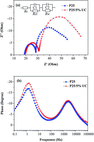 | ||
| Fig. 7 (a) EIS Nyquist plots and (b) Bode phase plots for DSSCs with 5% and without NaLuF4:Yb3+/Er3+. | ||
| Samples | Rs (Ω) | Rct (Ω) | Rw (Ω) | τe (ms) |
|---|---|---|---|---|
| P25 | 19.26 | 9.32 | 22.74 | 115.3 |
| P25/5% UC | 20.18 | 10.71 | 31.33 | 104.7 |
After considering the aforementioned results, we can conclude that NaLuF4:Yb3+/Er3+ can enhance power conversion efficiency because of its remarkable light scattering properties and UC luminescence. However, the intrinsic defects of NaLuF4:Yb3+/Er3+ materials are not beneficial for electron transfer, thereby reducing the photocurrent. Thus, the optimum doping amount was explored.
Conclusions
In summary, we synthesized a dual-functional material called NaLuF4:Yb3+/Er3+ through the co-precipitation method and then introduced the material into DSSCs. As a luminescence medium, the material efficiently converts IR to visible light, and this ability coincides well with the absorption range of N719 dye. With its excellent UC luminescence and light scattering properties of NaLuF4:Yb3+/Er3+ achieved 7.58% efficiency at concentration 5 wt%, which is 27.18% better than the efficiency of P25 photoanode (5.96%), and a 19.16% improvement in the photocurrent. This dual-functional NaLuF4:Yb3+/Er3+ material will provide a new strategy for enhancing photon harvesting in DSSCs.Acknowledgements
This work was supported by the NSFC (51572072 and 21402045) and the Ph.D. Programs Foundation of Ministry of Educational of China (20114208110004). This work was also financially supported by Wuhan Science and Technology Bureau of Hubei Province of China (2013010602010209), Educational commission of Hubei Province of China (D20141006) and Department of Science & Technology of Hubei Province of China (2015CFA118).Notes and references
- B. O'regan and M. Grätzel, Nature, 1991, 353, 737–740 CrossRef.
- D. B. Kuang, C. Klein, S. Ito, J. E. Moser, R. H. Baker, N. Evans, F. Duriaux, C. Grätzel, S. M. Zakeeruddin and M. Grätzel, Adv. Mater., 2007, 19, 1133–1137 CrossRef CAS.
- F. Gao, Y. Wang, D. Shi, J. Zhang, M. Wang, X. Jing, R. Humphry-Baker, P. Wang, S. M. Zakeeruddin and M. Grätzel, J. Am. Chem. Soc., 2008, 130, 10720–10728 CrossRef CAS PubMed.
- F. Sauvage, J. D. Decoppet, M. Zhang, S. M. Zakeeruddin, P. Comte, M. Nazeeruddin, P. Wang and M. Grätzel, J. Am. Chem. Soc., 2011, 133, 9304–9310 CrossRef CAS PubMed.
- A. Yella, H. W. Lee, H. N. Tsao, C. Y. Yi, A. K. Chandiran, M. K. Nazeeruddin, C. Y. Yeh, S. M. Zakeeruddin and M. Grätzel, Science, 2011, 334, 629–634 CrossRef CAS PubMed.
- S. Mathew, A. Yella, P. Gao, R. Humphry-Baker, B. F. Curchod, N. Ashari-Astani, I. Tavernelli, U. Rothlisberger, M. K. Nazeeruddin and M. Grätzel, Nat. Chem., 2014, 6, 242–247 CrossRef CAS PubMed.
- K. Kakiage, Y. Aoyama, T. Yano, K. Oya, J. I. Fujisawa and M. Hanaya, Chem. Commun., 2015, 51, 15894–15897 RSC.
- S. S. Mali, H. Kim, S. S. Chang, P. S. Patil, H. K. Jin and K. H. Chang, Sci. Rep., 2013, 3, 3004 CrossRef PubMed.
- M. Ye, C. Chen, M. Lv, D. Zheng, W. Guo and C. Lin, Nanoscale, 2013, 5, 6577–6583 RSC.
- G. Dai, L. Zhao, S. Wang, J. Hu, B. Dong, H. Lu and J. Li, J. Alloys Compd., 2012, 539, 264–270 CrossRef CAS.
- Y. Li, H. Wang, Q. Feng, G. Zhou and Z. S. Wang, Energy Environ. Sci., 2013, 6, 2156–2165 CAS.
- L. Zhao, C. Zhong, Y. Wang, S. Wang, B. Dong and L. Wan, J. Power Sources, 2015, 292, 49–57 CrossRef CAS.
- S. Mathew, A. Yella, P. Gao, R. Humphry-Baker, B. F. Curchod, N. Ashari-Astani and M. Grätzel, Nat. Chem., 2014, 6, 242–247 CrossRef CAS PubMed.
- S. P. Lim, A. Pandikumar, N. M. Huang and H. N. Lim, RSC Adv., 2015, 5, 44398–44407 RSC.
- K. Ueno and H. Misawa, NPG Asia Mater., 2013, 5, e61 CrossRef CAS.
- J. Zhang, H. Shen, W. Guo, S. Wang, C. Zhu, F. Xue and Z. Yuan, J. Power Sources, 2013, 226, 47–53 CrossRef CAS.
- F. Auzel, Chem. Rev., 2004, 104, 139–174 CrossRef CAS PubMed.
- J. Yu, Y. Yang, R. Fan, D. Liu, L. Wei, S. Chen and W. Cao, Inorg. Chem., 2014, 53, 8045–8053 CrossRef CAS PubMed.
- F. Meng, Y. Luo, Y. Zhou, J. Zhang, Y. Zheng, G. Cao and X. Tao, J. Power Sources, 2016, 316, 207–214 CrossRef CAS.
- J. Yu, Y. Yang, R. Fan, P. Wang and Y. Dong, Nanoscale, 2016, 8, 4173–4180 RSC.
- R. Schmechel, M. Kennedy, H. Von Seggern, H. Winkler, M. Kolbe, R. A. Fischer and H. Hahn, J. Appl. Phys., 2001, 89, 1679–1686 CrossRef CAS.
- W. N. Wang, W. Widiyastuti, T. Ogi, I. W. Lenggoro and K. Okuyama, Chem. Mater., 2007, 19, 1723–1730 CrossRef CAS.
- X. Tang, Z. Xu, Y. Liu, M. Liu, H. Wang and D. Chen, Energy Technol., 2015, 3, 1121–1129 CrossRef CAS.
- C. Yuan, G. Chen, P. N. Prasad, T. Y. Ohulchanskyy, Z. Ning, H. Tian and H. Ågren, J. Mater. Chem., 2012, 22, 16709–16713 RSC.
- C. W. Kim, W. J. Shin, M. J. Choi, J. H. Lee, S. H. Nam, Y. D. Suh and Y. S. Kang, J. Mater. Chem. A, 2016, 4, 11908–11915 CAS.
- F. Shi, J. Wang, X. Zhai, D. Zhao and W. Qin, CrystEngComm, 2011, 13, 3782–3787 RSC.
- C. Li, J. Yang, P. Yang, X. Zhang, H. Lian and J. Lin, Cryst. Growth Des., 2008, 8, 923–929 CAS.
- M. Miyauchi, M. Takashio and H. Tobimatsu, Langmuir, 2004, 20, 232–236 CrossRef CAS PubMed.
- J. B. Yin and X. P. Zhao, Chem. Mater., 2004, 16, 321–328 CrossRef CAS.
- H. C. Van de Hulst and V. Twersky, Phys. Today, 1957, 10, 28–30 CrossRef.
- Y. Z. Zheng, X. Tao, L. X. Wang, H. Xu, Q. Hou, W. L. Zhou and J. F. Chen, Chem. Mater., 2009, 22, 928–934 CrossRef.
- J. L. Su, S. K. Yong and D. W. Kim, Electrochem. Commun., 2010, 12, 1037–1040 CrossRef.
| This journal is © The Royal Society of Chemistry 2017 |

