 Open Access Article
Sustainable biobased blends of poly(lactic acid) (PLA) and poly(glycerol succinate-co-maleate) (PGSMA) with balanced performance prepared by dynamic vulcanization†
Oscar Valerio ab,
Manjusri Misra
 ab and
Amar K. Mohanty
 *ab
*ab
aSchool of Engineering, University of Guelph, Thornbrough Building, Guelph, N1G 2W1, Ontario, Canada. E-mail: mohanty@uoguelph.ca; Fax: +1-519-763-8933; Tel: +1-519-824-4120 ext. 56664
bBioproducts Discovery and Development Centre, Department of Plant Agriculture, University of Guelph, Crop Science Building, Guelph, N1G 2W1, Ontario, Canada
First published on 7th August 2017
Abstract
Biobased blends of poly(lactic acid) (PLA) and poly(glycerol succinate-co-maleate) (PGSMA) were fabricated by using a dynamic vulcanization strategy involving the simultaneous crosslinking and compatibilization of PGSMA within the PLA matrix on reactive extrusion. It was found that a balance between PLA/PGSMA compatibility and a low glass transition of PGSMA must be achieved in order to maximize the toughness of the blends. This was realized by setting the succinic acid to maleic anhydride content of the PGSMA synthesis to 1![[thin space (1/6-em)]](https://www.rsc.org/images/entities/char_2009.gif) :
:![[thin space (1/6-em)]](https://www.rsc.org/images/entities/char_2009.gif) 0.75
0.75![[thin space (1/6-em)]](https://www.rsc.org/images/entities/char_2009.gif) :
:![[thin space (1/6-em)]](https://www.rsc.org/images/entities/char_2009.gif) 0.25 mol glycerol
0.25 mol glycerol![[thin space (1/6-em)]](https://www.rsc.org/images/entities/char_2009.gif) :
:![[thin space (1/6-em)]](https://www.rsc.org/images/entities/char_2009.gif) succinic acid
succinic acid![[thin space (1/6-em)]](https://www.rsc.org/images/entities/char_2009.gif) :
:![[thin space (1/6-em)]](https://www.rsc.org/images/entities/char_2009.gif) maleic anhydride, yielding a C
maleic anhydride, yielding a C![[double bond, length as m-dash]](https://www.rsc.org/images/entities/char_e001.gif) C bearing reactive PGSMA with a glass transition of −1.69 °C, as determined by differential scanning calorimetry. The dynamically vulcanized PLA/PGSMA blends achieved an interfacial adhesion of B = 0.744 according to the Pukanszky model, which was attributed to the formation of PLA-g-PGSMA copolymers as shown by FTIR analysis. PLA shear yielding induced by PGSMA debonding was the main factor responsible for enhanced toughness in both tensile and impact testing. With an increase in PGSMA content of the blends, the average size of the PGSMA phase increased from 0.469 up to 0.649 μm, as shown by SEM imaging. With this, a higher number of debonded PGSMA particles were able to induce plastic deformation of the PLA matrix leading to tougher blends. Biobased dynamically vulcanized blends containing 60/40 wt% of PLA/PGSMA displayed an increment in their elongation at break and notched Izod impact resistance of 53% and 175% as compared with the neat PLA material.
C bearing reactive PGSMA with a glass transition of −1.69 °C, as determined by differential scanning calorimetry. The dynamically vulcanized PLA/PGSMA blends achieved an interfacial adhesion of B = 0.744 according to the Pukanszky model, which was attributed to the formation of PLA-g-PGSMA copolymers as shown by FTIR analysis. PLA shear yielding induced by PGSMA debonding was the main factor responsible for enhanced toughness in both tensile and impact testing. With an increase in PGSMA content of the blends, the average size of the PGSMA phase increased from 0.469 up to 0.649 μm, as shown by SEM imaging. With this, a higher number of debonded PGSMA particles were able to induce plastic deformation of the PLA matrix leading to tougher blends. Biobased dynamically vulcanized blends containing 60/40 wt% of PLA/PGSMA displayed an increment in their elongation at break and notched Izod impact resistance of 53% and 175% as compared with the neat PLA material.
1. Introduction
The usage of biopolymers has been extensively proposed as an alternative to mitigate the effects of petroleum dependence as well as to alleviate environmental concerns about the use of non-biodegradable materials.1 Poly(lactic acid) (PLA) is the frontrunner of bioplastics due to its excellent mechanical properties, compostability, biobased nature and a cost comparable to conventional polyolefins.2 PLA has been commercially adopted for some applications such as food packaging but the inherent brittleness of this polymer often limits its application where ductility of the material is required. In this regard, toughening of PLA aiming to increase its elongation at break and/or impact resistance has been a major research subject for the last decade. Successful toughening of PLA has been achieved by several strategies such as plasticization,3–9 modification of PLA chemical structure by grafting,10–12 introduction of pores into PLA materials,13 melt blending with rubbers14–18 and polymers,19–26 melt blending transesterification27–31 and dynamic vulcanization with reactive elastomers.32–37 Among these alternatives, those involving melt blending like plasticization, rubber toughening and dynamic vulcanization offer advantages in terms of scalability, cost and environmental friendliness.27,38 In particular, dynamic vulcanization is a very attractive strategy which involves the melt blending and simultaneous chemical reactions of PLA and a secondary (or more) polymer(s) and the formation of a crosslinked elastomeric phase within the PLA matrix.39 As a result, an in situ compatibilization effect is realized by the formation of PLA/secondary polymer copolymers which act as surfactants at the blend interface. PLA has been toughened by dynamic vulcanization using natural rubber, epoxidized synthetic elastomers and unsaturated polymers yielding supertough PLA based materials displaying impact resistance higher than 500 J m−1.33,35,37In light of the attractiveness of developing PLA toughened materials by the dynamic vulcanization method, we recently reported the toughening of PLA by using poly(glycerol succinate-co-maleate) (PGSMA) molecules in reactive extrusion experiments.40 These PGSMA polyesters can be considered as sustainable given that two of their monomer constituents, glycerol and succinic acid, are obtained at industrial level from biobased resources.41–44 Although the third monomer of PGSMA, maleic anhydride, is not biobased, scientific interest has been put on developing routes to biobased maleic acid and anhydride suggesting that industrial production of biobased maleic anhydride could be a reality in the future.45 Alternatively, itaconic acid and anhydride are emerging biobased molecules that have been suggested as replacement of petro based maleic anhydride in the synthesis of sustainable polymers at laboratory scale.46–48 These molecules could also be obtained at industrial levels from biobased resources in the future, provided that some key scientific challenges in fermentation and downstream processing are addressed, which could enable the process to be cost competitive compared to the petrochemical route.49,50
The usage of the dynamic vulcanization method allowed the utilization of PGSMA in thermoplastic blends in spite of its low molecular weight (∼1000 g mol−1) due to the occurrence of crosslinking of PGSMA during the extrusion process. In addition, our group has reported the utilization of poly(glycerol succinate) (PGS) gel polyesters as toughness enhancers for another biodegradable polymer, poly(butylene succinate) (PBS).51 In this case, the toughening was achieved in terms of notched Izod impact, with an increase of 200% in impact resistance after the addition of 30 wt% PGS to PBS. These earlier results led to the idea that optimizing a dynamic vulcanization process could help in overcoming difficulties on synthesis of PGS gel materials and render a PGSMA gel material created in situ for impact modification of polymers. Given the vast successful toughening of PLA in terms of notched Izod impact reported in scientific literature, in this research we aim to explore the utilization of PGSMA polyesters as impact enhancers for PLA. The mechanisms occurring in the dynamic vulcanization process of PLA/PGSMA blends have been investigated and this has been correlated with the mechanical properties of the system which has provided insights into the challenges and ways forward in the development of tough sustainable PLA/PGSMA blend materials.
2. Experimental
2.1 Materials
PLA (Ingeo 3251D) was purchased from Natureworks having a melting point of 155–170 °C and a melt flow index of 30–40 g/10 min (190 °C, 2.16 kg). Technical glycerol (G) was provided by a local biodiesel producer (BIOX Corporation, Canada) having a glycerol content of 95 wt%.52 Succinic acid (S) (99+ wt%, KIC chemicals, UK), maleic anhydride (MA) (99 wt%, Sigma Aldrich) and tetrahydrofuran (99.8 wt%, Fisher Scientific, Canada) were purchased and used as received. 2,5-Bis(tert-butyl-peroxy)-2,5-dimethylhexane (Luperox 101, technical grade 90%, Sigma Aldrich) was used as free radical initiator on dynamic vulcanization.2.2 Synthesis of poly(glycerol succinate-co-maleate) (PGSMA)
Poly(glycerol succinate-co-maleate) polyesters were synthesized in a one pot procedure without solvents or catalyst as reported before.40 The ratio of succinic acid to maleic anhydride was changed in different PGSMA formulations to investigate the effect of the C![[double bond, length as m-dash]](https://www.rsc.org/images/entities/char_e001.gif) C content on PGSMA. The reaction was monitored by measuring the viscosity of the product in a cone plate rheometer at 100 °C and 100 s−1 (CAP 2000+, Brookfield, USA) and stopped by removing the vessel from the heater when the viscosity was in the range of 200–300 Poise to obtain PGSMA of the highest molecular weight possible before gelation.53
C content on PGSMA. The reaction was monitored by measuring the viscosity of the product in a cone plate rheometer at 100 °C and 100 s−1 (CAP 2000+, Brookfield, USA) and stopped by removing the vessel from the heater when the viscosity was in the range of 200–300 Poise to obtain PGSMA of the highest molecular weight possible before gelation.53
2.3 PGSMA characterizations
FTIR spectra of PGSMA was collected in 64 scans at a resolution of 4 cm−1 on a Nicolet 6700 FTIR spectrometer equipped with an attenuated total reflection (ATR) accessory. Molecular weight determination was carried on a Viscotek GPCmax system (Malvern Instruments, UK) as reported before.40 A calibration curve for molecular weight (Mn) was constructed using eight polyethylene glycol standards with Mn in the range of 106–7830 g mol−1 (Easy Vial, Agilent Technologies, USA).2.4 Melt blending of PLA and PGSMA products
The blending of PLA and PGSMA was carried in a laboratory scale twin screw extruder (Xplore, DSM, Netherlands) as reported before.40 PLA, PGSMA and a predetermined amount of free radical initiator were introduced simultaneously to the extruder chamber kept at 180 °C and mixed for 2 min at 100 rpm followed by injection molding at 30 °C. A sample of neat PLA was compounded in presence of 0.2 phr free radical initiator. This control sample was denoted as RPLA throughout the manuscript.2.5 Mechanical testing
Tensile testing was carried on an Instron universal testing machine (Instron, Canada) using five type IV specimens according to ASTM D638 with a testing speed of 50 mm min−1. Notched Izod impact was tested on an impact testing machine using a hammer of 0.5–5 ft lbs according to the procedure described on ASTM D256 standard. The samples were notched 48 h prior to the test.2.6 Thermal characterization
Thermal properties of the materials were studied by differential scanning calorimetry (DSC Q200, TA instruments). Samples of 5–10 mg were placed on sealed aluminum pans under a nitrogen flow of 50 mL min−1. The samples were equilibrated at −30 °C followed by a heating ramp of 10 °C min−1 to 180 °C. The glass transition temperatures of PGSMA and PLA as well as the percentage of crystallinity of PLA were calculated using data from the first heating cycle. For the determination of the PLA crystallinity percentage (Xc), the following formula was employed
 | (1) |
2.7 Dynamic mechanical analysis
Dynamic mechanical analysis of PLA/PGSMA samples was carried on a Q800 DMA (TA instruments, USA). Samples were equilibrated at −100 °C for 10 min and then heated at 3 °C min−1 to 100 °C. A periodic deformation of 0.02% strain was applied at 1 Hz in dual cantilever mode. The storage (E′) to loss (E′′) modulus ratio (tan![[thin space (1/6-em)]](https://www.rsc.org/images/entities/char_2009.gif) δ) was plotted as function of the temperature.
δ) was plotted as function of the temperature.
2.8 Gel fraction determination
Gel fraction determination was performed by dissolution in tetrahydrofuran (THF) as reported before.40 PLA/PGSMA samples of about 200 mg (mi) were dissolved in 30 mL of THF at 50 °C and the undissolved residue (mf) was separated by centrifugation, washed with fresh THF and dried at 80 °C to remove residual solvent. The gel fraction was calculated as
 | (2) |
2.9 Scanning electron microscopy
Scanning electron microscopy imaging was performed on the fractured surface of tested notched Izod impact specimens of PLA/PGSMA blends on a Phenom ProX scanning electron microscope (Phenom-World VB, The Netherlands). Samples were coated with a fine layer of gold prior to observation to prevent deformation at high magnifications. For performing the particle size calculation of PGSMA phase, images were analyzed using the software ImageJ. At least 200 PGSMA particles were measured for each blend formulation in terms of diameter for calculating the size distribution.3. Results and discussion
3.1 Effect of succinic acid to maleic anhydride on PGSMA synthesis and blending
Table 1 shows the PGSMA formulations employed as well as molecular weight characterization. It can be seen that by monitoring the reaction viscosity, PGSMA products of similar molecular weight were obtained for different monomer composition. This allows to properly compare the PGSMA effect on dynamically vulcanized PLA/PGSMA blends.| Sample | Monomer composition (mol G![[thin space (1/6-em)]](https://www.rsc.org/images/entities/char_2009.gif) : :![[thin space (1/6-em)]](https://www.rsc.org/images/entities/char_2009.gif) mol S mol S![[thin space (1/6-em)]](https://www.rsc.org/images/entities/char_2009.gif) : :![[thin space (1/6-em)]](https://www.rsc.org/images/entities/char_2009.gif) mol MA) mol MA) |
Reaction time (h) | Viscosity (Poise) | Mn (Da) | Mw/Mn () |
|---|---|---|---|---|---|
| PGSMA 100–0 | 1![[thin space (1/6-em)]](https://www.rsc.org/images/entities/char_2009.gif) : :![[thin space (1/6-em)]](https://www.rsc.org/images/entities/char_2009.gif) 1 1![[thin space (1/6-em)]](https://www.rsc.org/images/entities/char_2009.gif) : :![[thin space (1/6-em)]](https://www.rsc.org/images/entities/char_2009.gif) 0 0 |
8.5 | 221 ± 14 | 1280 ± 57 | 4.2 ± 0.3 |
| PGSMA 75–25 | 1![[thin space (1/6-em)]](https://www.rsc.org/images/entities/char_2009.gif) : :![[thin space (1/6-em)]](https://www.rsc.org/images/entities/char_2009.gif) 0.75 0.75![[thin space (1/6-em)]](https://www.rsc.org/images/entities/char_2009.gif) : :![[thin space (1/6-em)]](https://www.rsc.org/images/entities/char_2009.gif) 0.25 0.25 |
6.3 | 291 ± 9 | 1251 ± 31 | 4.6 ± 0.3 |
| PGSMA 50–50 | 1![[thin space (1/6-em)]](https://www.rsc.org/images/entities/char_2009.gif) : :![[thin space (1/6-em)]](https://www.rsc.org/images/entities/char_2009.gif) 0.5 0.5![[thin space (1/6-em)]](https://www.rsc.org/images/entities/char_2009.gif) : :![[thin space (1/6-em)]](https://www.rsc.org/images/entities/char_2009.gif) 0.5 0.5 |
5.1 | 284 ± 16 | 1255 ± 165 | 4.5 ± 0.9 |
| PGSMA 25–75 | 1![[thin space (1/6-em)]](https://www.rsc.org/images/entities/char_2009.gif) : :![[thin space (1/6-em)]](https://www.rsc.org/images/entities/char_2009.gif) 0.25 0.25![[thin space (1/6-em)]](https://www.rsc.org/images/entities/char_2009.gif) : :![[thin space (1/6-em)]](https://www.rsc.org/images/entities/char_2009.gif) 0.75 0.75 |
3.8 | 265 ± 6 | 1035 ± 70 | 3.8 ± 0.4 |
| PGSMA 0–100 | 1![[thin space (1/6-em)]](https://www.rsc.org/images/entities/char_2009.gif) : :![[thin space (1/6-em)]](https://www.rsc.org/images/entities/char_2009.gif) 0 0![[thin space (1/6-em)]](https://www.rsc.org/images/entities/char_2009.gif) : :![[thin space (1/6-em)]](https://www.rsc.org/images/entities/char_2009.gif) 1 1 |
2.8 | 275 ± 15 | 906 ± 103 | 3.6 ± 0.4 |
With decreasing mol ratio of succinic acid to maleic anhydride (SMA) the infrared spectra of the PGSMA products showed an increase in the peak at 1644 cm−1 (Fig. 1). This peak has been attributed to C![[double bond, length as m-dash]](https://www.rsc.org/images/entities/char_e001.gif) C bonds on previous studies.38 Thus the number of unsaturations (C
C bonds on previous studies.38 Thus the number of unsaturations (C![[double bond, length as m-dash]](https://www.rsc.org/images/entities/char_e001.gif) C bonds) on PGSMA can be manipulated by changing the monomer composition of the synthesis.
C bonds) on PGSMA can be manipulated by changing the monomer composition of the synthesis.
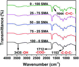 | ||
| Fig. 1 Infrared spectra of synthesized PGSMA products. (SMA: molar ratio of succinic acid/maleic anhydride employed in the formulation). | ||
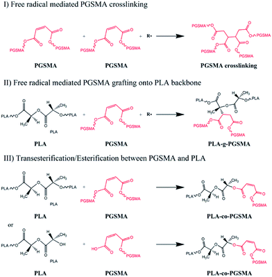
The melt compounding of PLA and PGSMA in presence of a free radical initiator could lead to different reaction products, as shown in Scheme 1. Free radicals formed could attack the C![[double bond, length as m-dash]](https://www.rsc.org/images/entities/char_e001.gif) C double bond on PGSMA molecules, creating PGSMA macroradicals. These could react among themselves to form crosslinked PGSMA (I in Scheme 1). Simultaneously, free radicals could promote hydrogen abstraction from PLA backbone which could be attacked by PGSMA macroradicals. This would result on the grafting of PGSMA molecules onto the PLA backbone yielding PLA-g-PGSMA copolymers (II on Scheme 1). Another possibility is the transesterification between ester groups on PLA and PGSMA and/or the esterification reaction between OH and COOH end groups on PLA or PGSMA (III on Scheme 1). Although this third reaction is possible, the transesterification of PLA and polyesters is usually realized only in the presence of transesterification catalysts and at residence times higher than the used in the present study.27,55 Moreover, in our previous study we showed that the compounding of PGSMA and PLA in absence of free radical initiator did not increase toughness of the resulting material, whereas in the presence of free radical initiator the toughness of the blend increased by 392% as compared to neat PLA.40 Thus, it can be concluded that the main reactions taking place during the dynamic vulcanization of PLA and PGSMA are the PGSMA self crosslinking and PLA-g-PGSMA formation. The grafting of C
C double bond on PGSMA molecules, creating PGSMA macroradicals. These could react among themselves to form crosslinked PGSMA (I in Scheme 1). Simultaneously, free radicals could promote hydrogen abstraction from PLA backbone which could be attacked by PGSMA macroradicals. This would result on the grafting of PGSMA molecules onto the PLA backbone yielding PLA-g-PGSMA copolymers (II on Scheme 1). Another possibility is the transesterification between ester groups on PLA and PGSMA and/or the esterification reaction between OH and COOH end groups on PLA or PGSMA (III on Scheme 1). Although this third reaction is possible, the transesterification of PLA and polyesters is usually realized only in the presence of transesterification catalysts and at residence times higher than the used in the present study.27,55 Moreover, in our previous study we showed that the compounding of PGSMA and PLA in absence of free radical initiator did not increase toughness of the resulting material, whereas in the presence of free radical initiator the toughness of the blend increased by 392% as compared to neat PLA.40 Thus, it can be concluded that the main reactions taking place during the dynamic vulcanization of PLA and PGSMA are the PGSMA self crosslinking and PLA-g-PGSMA formation. The grafting of C![[double bond, length as m-dash]](https://www.rsc.org/images/entities/char_e001.gif) C containing polymers onto PLA mediated by free radical initiators has been also described by previous researchers in dynamic vulcanization studies.33,38,56
C containing polymers onto PLA mediated by free radical initiators has been also described by previous researchers in dynamic vulcanization studies.33,38,56
Fig. 2 shows tensile toughness (calculated as area under the stress strain curve) and impact resistance of PLA/PGSMA dynamically vulcanized blends. These blends were compounded using a fix free radical initiator loading (1 wt% initiator by PGSMA weight).
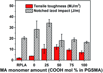 | ||
| Fig. 2 Tensile toughness and notched Izod impact of dynamically vulcanized 80/20 wt% PLA/PGSMA blends. | ||
The crystallinity of PLA phase in the blends (Fig. S1†) was not significantly affected and consequently it can be excluded from the mechanical analysis.33 With an increase in maleic anhydride content in the PGSMA phase, it is likely that a higher crosslinking density could be achieved on PGSMA phase (reaction I in Scheme 1). Similarly, grafting of PGSMA onto PLA could be favored with a higher concentration of C![[double bond, length as m-dash]](https://www.rsc.org/images/entities/char_e001.gif) C double bonds on the reactive extrusion system (reaction II in Scheme 1). The glass transition temperature of the PGSMA phase obtained by DSC analysis and the gel fraction of the blends increased with increasing maleic anhydride content in PGSMA phase (Fig. S1†). The increased gel fraction suggests that with higher content of C
C double bonds on the reactive extrusion system (reaction II in Scheme 1). The glass transition temperature of the PGSMA phase obtained by DSC analysis and the gel fraction of the blends increased with increasing maleic anhydride content in PGSMA phase (Fig. S1†). The increased gel fraction suggests that with higher content of C![[double bond, length as m-dash]](https://www.rsc.org/images/entities/char_e001.gif) C bonds in the backbone of PGSMA, a higher crosslinking percentage of this phase is achieved. This could also be ascribed to the higher occurrence of PLA grafting onto the PGSMA crosslinked structure. An increment of glass transition temperature has been correlated with an increased crosslinking density in poly(glycerol sebacate) polyesters with similar hyperbranched architecture than PGSMA.57 Dynamic mechanical analysis (Fig. 3) confirmed the increase in glass transition of PGSMA shown by DSC and revealed that the damping capacity of the PGSMA phase decreased with increased content of maleic anhydride on the formulation (Fig. 3a). Moreover, the damping capacity and glass transition temperature of the PLA phase reduced monotonically with the increase of maleic anhydride in the PGSMA formulation (Fig. 3b). The shifting in glass transition of the blend components towards each other indicates a better compatibility is achieved on the system with increasing maleic anhydride on PGSMA. This can be explained by the increased concentration of PLA-g-PGSMA molecules formed as a result of the higher presence of reactive C
C bonds in the backbone of PGSMA, a higher crosslinking percentage of this phase is achieved. This could also be ascribed to the higher occurrence of PLA grafting onto the PGSMA crosslinked structure. An increment of glass transition temperature has been correlated with an increased crosslinking density in poly(glycerol sebacate) polyesters with similar hyperbranched architecture than PGSMA.57 Dynamic mechanical analysis (Fig. 3) confirmed the increase in glass transition of PGSMA shown by DSC and revealed that the damping capacity of the PGSMA phase decreased with increased content of maleic anhydride on the formulation (Fig. 3a). Moreover, the damping capacity and glass transition temperature of the PLA phase reduced monotonically with the increase of maleic anhydride in the PGSMA formulation (Fig. 3b). The shifting in glass transition of the blend components towards each other indicates a better compatibility is achieved on the system with increasing maleic anhydride on PGSMA. This can be explained by the increased concentration of PLA-g-PGSMA molecules formed as a result of the higher presence of reactive C![[double bond, length as m-dash]](https://www.rsc.org/images/entities/char_e001.gif) C bonds on the reactive extrusion. A decreased damping capacity indicates a hindered molecular mobility of the amorphous polymer phase. On the PGSMA network, this could be attributed to the achievement of a higher crosslinking density, as suggested by previous studies involving dynamic vulcanization of PLA and reactive elastomers.32 Also, the decrease in damping capacity of PGSMA could be related to a higher interfacial adhesion to PLA phase as a result of the increased concentration of PLA-g-PGSMA species, causing the restriction on PGSMA mobility. In consequence, as PGSMA crosslinking density increases and the interfacial adhesion is promoted by PLA-g-PGSMA species, the molecular mobility of the overall system decreases. This leads to the decrease on impact resistance of the PLA/PGSMA blends with maleic anhydride higher than 25%. The specific contribution of each mechanism (PGSMA crosslinking and grafting to PLA) to the mechanical behavior remains a challenge and further experimental work is required given the difficulty on quantifying accurately the amount of PLA-g-PGSMA species formed. Nevertheless, the formation of the PLA-g-PGSMA species was clearly demonstrated in the following sections.
C bonds on the reactive extrusion. A decreased damping capacity indicates a hindered molecular mobility of the amorphous polymer phase. On the PGSMA network, this could be attributed to the achievement of a higher crosslinking density, as suggested by previous studies involving dynamic vulcanization of PLA and reactive elastomers.32 Also, the decrease in damping capacity of PGSMA could be related to a higher interfacial adhesion to PLA phase as a result of the increased concentration of PLA-g-PGSMA species, causing the restriction on PGSMA mobility. In consequence, as PGSMA crosslinking density increases and the interfacial adhesion is promoted by PLA-g-PGSMA species, the molecular mobility of the overall system decreases. This leads to the decrease on impact resistance of the PLA/PGSMA blends with maleic anhydride higher than 25%. The specific contribution of each mechanism (PGSMA crosslinking and grafting to PLA) to the mechanical behavior remains a challenge and further experimental work is required given the difficulty on quantifying accurately the amount of PLA-g-PGSMA species formed. Nevertheless, the formation of the PLA-g-PGSMA species was clearly demonstrated in the following sections.
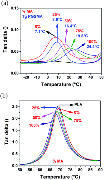 | ||
| Fig. 3 tan delta of (a) PGSMA phase and (b) PLA phase of dynamically vulcanized 80/20 wt% PLA/PGSMA blends. | ||
Fig. 4 shows a zoom in the ester peak of both the neat PGSMA products and the gel PGSMA phase extracted from the reactive PLA/PGSMA blends (1500–1900 cm−1 region).
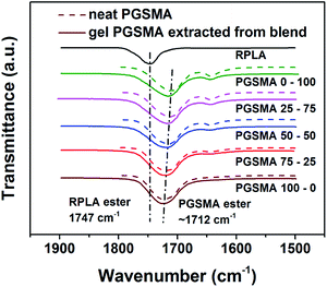 | ||
| Fig. 4 FTIR spectra of neat PGSMA products (dashed line) and PGSMA fraction extracted from dynamically vulcanized 80/20 wt% PLA/PGSMA blends. | ||
When comparing the ester peak of the neat PGSMA products (dashed line) to the gel extracted from the blend (solid line) a clear shift towards the PLA ester peak at 1747 cm−1 is noticeable for maleic anhydride content higher than 50%, whereas for PGSMA formulations with lower maleic anhydride content this peak remains unshifted in the gel PGSMA compared to the neat PGSMA. As demonstrated in our earlier work, a shift of the ester PGSMA peak in the PLA/PGSMA reactive blends can be attributed to the formation of PLA-g-PGSMA copolymers.40 Thus, with higher content of maleic anhydride in the PGSMA formulations, a higher formation of PLA-g-PGSMA copolymers seems to occur. These copolymers would be located at the interface of both blend components increasing the interfacial adhesion.
The formation of PLA-g-PGSMA species should also increase the tensile strength of the system, as seen in Fig. S2.† The Pukanszky model has been commonly used in PLA blends to analyze the interfacial adhesion between the phases in the blend.27,58,59 This model predicts that the stress at yield in a binary polymer blend can be calculated as:
 | (3) |
Ultimately the toughness of the dynamically vulcanized PLA/PGSMA system was favored by the balance achieved between an slightly crosslinked PGSMA phase allowing for a low glass transition temperature and the formation of PLA-g-PGSMA copolymers which allow for an effective load transfer between the phases. Similar mechanical behavior was observed by Zhang et al.;56 the competition between the self-crosslinking of the secondary polymer and the amount of PLA/secondary polymer graft copolymer formed determines the elongation and impact behavior on PLA/unsaturated elastomer reactive blends mediated by free radical initiators. Both the glass transition of the elastomer and the interfacial adhesion are major contributors to the toughness of thermoplastic-elastomer blend systems.60
3.2 Effect of PLA to PGSMA ratio
After studying the effects of the different formulations of PGSMA a series of blends of PLA and PGSMA 75–25 SMA were prepared using a fixed concentration of initiator (1 wt% by PGSMA weight) and various weight ratios of PLA/PGSMA. Our aim was to investigate the mechanical properties of the binary blend at higher loadings of PGSMA and the mechanisms underlying these effects. In another series of experiments, the effect of the initiator was investigated. It was observed that at higher initiator loadings the toughness of the system was not significantly improved (Fig. S3†). Moreover, a slight decrease on the PLA glass transition together with the appearance of a double melting peak of PLA was observed on DSC experiments (Fig. S4 and Table S1†). Previous research has suggested that the appearance of a secondary melting peak at lower temperature is a consequence of the formation of PLA graft copolymers with the secondary polymer, leading to the formation of imperfect crystals.38 In the present study, the formation of PLA-g-PGSMA molecules could be favored with increased initiator loadings which could promote the formation of imperfect PLA crystals and additionally decrease PLA glass transition as shown in the previous section. Other researchers have suggested that higher initiator loadings could result in increased PLA chain breakage, which could also promote a plasticization effect on PLA decreasing its Tg.56 Further research could help in clarifying these effects. In regards to our aim of increasing toughness in the PLA/PGSMA blend, the concentration of initiator was fixed to 1 wt% by PGSMA weight, given that the toughness of the blends is not significantly enhanced with increasing initiator loadings.The mechanical behavior of the dynamically vulcanized PLA/PGSMA blends can be observed in Table 2. The tensile strength and modulus of the blends were decreased monotonically with the addition of PGSMA due to its elastomeric nature. The elongation at break of the blends increased monotonically with the load of PGSMA. This could be due to either a mechanism of PGSMA debonding followed by stable void growing or by stress transfer and deformation of PGSMA particles or a combination thereof. Both of these plausible mechanisms have shown effective on inducing PLA shear yielding, increasing elongation at break in PLA systems.13,61
| PGSMA in blend (wt%) | σ (MPa) | E (MPa) | εb (%) | Tensile toughness (MJ m−3) | Notched Izod impact (J m−1) |
|---|---|---|---|---|---|
| 40 | 32.2 ± 0.9 | 1879 ± 89 | 55.3 ± 11 | 13.6 ± 2.9 | 55.4 ± 7.1 |
| 30 | 43.1 ± 0.5 | 2519 ± 103 | 45.2 ± 8.1 | 13.8 ± 2.3 | 37.3 ± 3.4 |
| 20 | 47.7 ± 0.6 | 2804 ± 88 | 29.5 ± 7.3 | 9.3 ± 1.9 | 40.3 ± 4.4 |
| 10 | 60.8 ± 0.6 | 3449 ± 94 | 11 ± 2.1 | 4.3 ± 0.7 | 27.9 ± 6.6 |
| 0 | 81.1 ± 0.5 | 4081 ± 183 | 3.6 ± 0.3 | 2 ± 0.3 | 20.4 ± 1.4 |
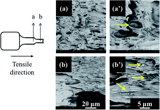
In order to confirm the mechanism of toughening on tensile testing, scanning electron microscopy observations were taken on cryofractured tensile specimens. In these images (Fig. 6) the cross section of the tested tensile specimens was photographed aiming to observe the behavior of the PGSMA particles upon tensile loading. The observations revealed that debonding of PGSMA occurs upon tensile testing, followed by stable void growth from debonded PGSMA particles. In addition, PLA matrix showed evidence of extensive shear yielding after PGSMA debonding. Thus, the enhanced tensile toughness in the system can be attributed mainly to PLA shear yielding induced by PGSMA debonding.
Elongation at break and tensile modulus of the system were modeled by a linear trend with respect to PGSMA load (Fig. S5†). The tensile strength of the system was modeled in terms of the Pukanszky model for binary blends (eqn (3)). The coefficient B, representative of interfacial adhesion on the binary blend was obtained by linearizing eqn (3) as shown by previous researchers (Fig. S6†).58,62,63 A B parameter equal to 0.744 was obtained using this approach. Previous researchers have reported values of B in the range of 2.38–3.77 for PLA blend systems.62,63 Although these values seem higher, they were calculated using a much lower strain rate for testing (1.7 × 10⁻³ s−1 versus 12.8 × 10⁻³ s−1 in the present study). Thus, the value of B is not directly comparable to literature reported values due to the dependence of interfacial adhesion on the nominal strain rate employed for testing.64 Nevertheless, the experimental data for tensile strength seems to be in close agreement with the Pukanszky model (Fig. S7†) which agrees with the formation of PLA-g-PGSMA copolymers acting as compatibilizers as discussed before.
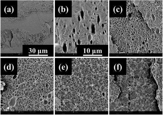
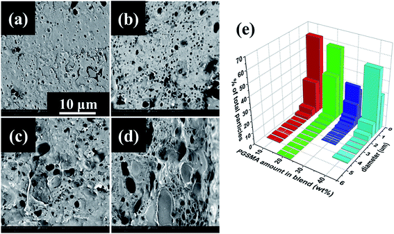
Notched Izod impact resistance is indicative of dynamic toughness of the PLA/PGSMA system as is carried at strain rates much higher than conventional uniaxial tensile testing. In average, both tensile toughness and impact resistance were increased with the addition of PGSMA as can be observed in Table 2 but the trend was not linear as in the case of elongation at break. The SEM observation of the fracture site on notched Izod impact tested specimens of PLA/PGSMA reactive blends (Fig. 7) provided evidence of a low interfacial adhesion of PGSMA to PLA upon impact testing; PGSMA rubbery particles were pulled out of the PLA matrix due to the interfacial adhesion being overcome by the high strain rate of impact testing. Wu observed a similar behavior on a rubber toughened thermoplastic system displaying low interfacial adhesion.64
The images in Fig. 7a–d were analyzed by measuring the diameter of at least 200 PGSMA particles and particle size distributions were calculated (Fig. 7e). The reason for change of diameter of PGSMA particles could be the competition of a decrease in viscosity of the blend and an increase of coalescence of secondary phase particles at higher loads of PGSMA. At loads of PGSMA lower than 20 wt% the decrease of viscosity on the blend is not enough for allowing a breakage of PGSMA into very fine droplets upon blending, causing the presence of larger particles. After 30 wt% PGSMA load, PGSMA dispersion into fine droplets takes place at the beginning of the blending process but a higher occurrence of coalescence as a consequence of the lower viscosity and higher concentration of PGSMA can be expected. Thus a balance between these two processes in the case of the 70/30 wt% PLA/PGSMA blend could cause the absence of larger PGSMA particles (d > 3.5 μm). To get a better understanding of the variations on impact resistance results an analysis of the toughening mechanisms on the PLA/PGSMA blends was carried. As suggested in literature, in a successfully toughened PLA blend the impact energy is dissipated as a combination of multiple crazing of PLA, cavitation and deformation of secondary phase, shear yielding of PLA ligaments and debonding of secondary phase leading to crack growth and failure.2 For simplicity and in analogy to linear elastic fracture mechanics approaches,65,66 it can be assumed a linear relation of the energy contributions to the impact strength as:
| IS = Ecrazing + Ecavitation + Eshear yielding + Edebonding | (4) |
From the observation of PGSMA pulled out from PLA in SEM it can be assumed that plastic deformation of the secondary phase is not achieved and the term for cavitation in eqn (4) can be disregarded giving
| IS = Ecrazing + Eshear yielding + Edebonding | (5) |
For thermoplastic system filled with weakly bonded spherical particles earlier studies have modeled the toughness of the system including energy contributions from the matrix crazing and shear banding and from the debonding/cavitation of the particles followed by plastic void growth of the matrix.65,66 The energy contribution of the debonding, cavitation, plastic void growth and shear banding has been modeled as a function of the volumetric fraction of voids on the plastic deformation zone in front of the crack tip.66 Other authors have defined this contribution as proportional to the surface area of the particles involved on the plastic deformation zone.65 Both of these parameters are proportional (up to a certain limit) to the volume fraction of filler66 and hence they should be also proportional to the weight fraction of gel PGSMA on the present system. The contribution of the crazing mechanism has been modeled as proportional to the ligament thickness T, defined as the minimum distance between two adjacent particles of secondary phase on the matrix.66 Liu established that in a binary blend the ligament thickness T can be calculated using67
 | (6) |
| IS = 17 + 15.2T′ + 30.4w′ | (7) |
With a R-squared value of 0.999 and a R-squared adjusted value of 0.997 indicating a good fitting to the experimental data. The fact that the notched Izod experimental data can be well represented by the linear contributions of the matrix crazing and plastic deformation further confirms that at high strain rates debonding is taking place before plastic deformation of the PGSMA phase in the PLA/PGSMA system. Therefore, strategies for improving the interfacial adhesion between both blend components while keeping a low glass transition of PGSMA could help on increasing stress transfer and deformation of PGSMA, improving impact resistance of the system. Fig. 8 gives an estimation of the contributions of matrix crazing and matrix plastic deformation to the total impact energy accounted. The root cause for the variations on energy dissipation mechanisms is the particle size distribution of PGSMA. Bucknall and Paul68,69 demonstrated through a linear elastic fracture mechanics approach that in a binary polymer blend an optimum particle size range exists that enables internal particle cavitation followed by plastic deformation of the matrix achieving maximum toughening. For quasi-amorphous PLA blends, the optimum size of the secondary phase has been reported in the range of 0.7–1.1 μm.32,33,61 Moreover, these authors showed that on the microscopic deformation processes taking place in front of the crack tip, large particles tend to induce crazing of the matrix whereas smaller particles favor yielding of the matrix. Therefore, in the case of a distribution of size as in the PLA/PGSMA blends the larger particles will contribute to craze initiation whereas particles on the optimum size and smaller will favor plastic deformation. As shown in Fig. 7, the average particle size of the PGSMA particles tends to increase with increasing loads of PGSMA (from 0.469 up to 0.649 μm). With this, a larger proportion of PGSMA particles fall on the range of size that induces primarily PLA plastic deformation and yielding (0.7–1.1 μm) which explains the higher contribution of these mechanisms to toughening at PGSMA loads higher than 20 wt%. The presence of large particles (d > 3.5 μm) primarily on blends containing 10, 20 and 40 wt% of PGSMA explains the occurrence of crazing in these blends. Although all weakly bonded particles could act as initiation sites for crazing, in practice the larger PGSMA particles are able to debond at early stages of crack propagation, before other smaller PGSMA particles, and crazing can start preferentially at these initiation sites.68,69 Then, particles smaller than the optimum size (0.7–1.1 μm) are ineffective on terminating the growing crazes, leading to fast crack propagation and failure.61
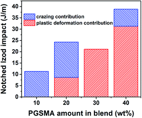 | ||
| Fig. 8 Impact energy of PLA/PGSMA dynamically vulcanized blends as a function of individual contributions of matrix crazing and matrix plastic deformation. | ||
4. Conclusions
The dynamic vulcanization of PLA and PGSMA was investigated in detail aiming to increase the toughness of PLA. In terms of PGSMA synthesis, it was found that maintaining a low glass transition temperature while enabling in situ formation of PLA-g-PGSMA molecules by C![[double bond, length as m-dash]](https://www.rsc.org/images/entities/char_e001.gif) C grafting of PGSMA to PLA are the main parameters responsible for controlling toughness on the blends. A balance between these two parameters was achieved at a composition of 1
C grafting of PGSMA to PLA are the main parameters responsible for controlling toughness on the blends. A balance between these two parameters was achieved at a composition of 1![[thin space (1/6-em)]](https://www.rsc.org/images/entities/char_2009.gif) :
:![[thin space (1/6-em)]](https://www.rsc.org/images/entities/char_2009.gif) 0.75
0.75![[thin space (1/6-em)]](https://www.rsc.org/images/entities/char_2009.gif) :
:![[thin space (1/6-em)]](https://www.rsc.org/images/entities/char_2009.gif) 0.25 mol glycerol
0.25 mol glycerol![[thin space (1/6-em)]](https://www.rsc.org/images/entities/char_2009.gif) :
:![[thin space (1/6-em)]](https://www.rsc.org/images/entities/char_2009.gif) succinic acid
succinic acid![[thin space (1/6-em)]](https://www.rsc.org/images/entities/char_2009.gif) :
:![[thin space (1/6-em)]](https://www.rsc.org/images/entities/char_2009.gif) maleic anhydride. Increasing the amount of PGSMA into the blend showed effective on monotonically increasing toughness of the system both in terms of elongation at break and notched Izod impact. Tensile toughness was enhanced through debonding of PGSMA particles enabling PLA matrix shear yielding. In the case of impact resistance, the toughening effects were controlled by the distribution of size of PGSMA within PLA. The blend of 60/40 PLA/PGSMA displayed an enhancement of 53 and 175% on elongation at break and notched Izod impact respectively as compared to neat PLA.
maleic anhydride. Increasing the amount of PGSMA into the blend showed effective on monotonically increasing toughness of the system both in terms of elongation at break and notched Izod impact. Tensile toughness was enhanced through debonding of PGSMA particles enabling PLA matrix shear yielding. In the case of impact resistance, the toughening effects were controlled by the distribution of size of PGSMA within PLA. The blend of 60/40 PLA/PGSMA displayed an enhancement of 53 and 175% on elongation at break and notched Izod impact respectively as compared to neat PLA.
Conflicts of interest
There are no conflicts of interest to declare.Acknowledgements
The authors are thankful to the Chilean National Scholarship Program for Graduate Studies from CONICYT-Chile; the Ontario Ministry of Agriculture, Food and Rural Affairs (OMAFRA), Canada/University of Guelph-Bioeconomy for Industrial Uses Research Program Theme (Project # 200001 and 200283); OMAFRA, Canada New Directions Project #050155; Ontario Ministry of Research, Innovation and Science (MRIS), Ontario Research Fund, Research Excellence Program; Round-7 (ORF-RE07) from the (Project #052644 and 052665); the Natural Sciences and Engineering Research Council (NSERC), Canada – Discovery Grants (Project # 401111) for the financial support to carry out this research work.References
- M. M. Reddy, S. Vivekanandhan, M. Misra, S. K. Bhatia and A. K. Mohanty, Prog. Polym. Sci., 2013, 38, 1653–1689 CrossRef CAS.
- G. Kfoury, J.-M. Raquez, F. Hassouna, J. Odent, V. Toniazzo, D. Ruch and P. Dubois, Front. Chem., 2013, 1, 1–46 CAS.
- Z. Kulinski and E. Piorkowska, Polymer, 2005, 46, 10290–10300 CrossRef CAS.
- Z. Kulinski, E. Piorkowska, K. Gadzinowska and M. Stasiak, Biomacromolecules, 2006, 7, 2128–2135 CrossRef CAS PubMed.
- N. Ljungberg, T. Andersson and B. Wesslén, J. Appl. Polym. Sci., 2003, 88, 3239–3247 CrossRef CAS.
- O. Martin and L. Avérous, Polymer, 2001, 42, 6209–6219 CrossRef CAS.
- E. Piorkowska, Z. Kulinski, A. Galeski and R. Masirek, Polymer, 2006, 47, 7178–7188 CrossRef CAS.
- A. Ruellan, A. Guinault, C. Sollogoub, V. Ducruet and S. Domenek, J. Appl. Polym. Sci., 2015, 132, 42476 CrossRef.
- K. Okamoto, T. Ichikawa, T. Yokohara and M. Yamaguchi, Eur. Polym. J., 2009, 45, 2304–2312 CrossRef CAS.
- N. C. Thanh, C. Ruksakulpiwat and Y. Ruksakulpiwat, J. Mater. Sci. Chem. Eng., 2015, 03, 102–107 Search PubMed.
- F. Hassouna, J.-M. Raquez, F. Addiego, V. Toniazzo, P. Dubois and D. Ruch, Eur. Polym. J., 2012, 48, 404–415 CrossRef CAS.
- F. Hassouna, J.-M. Raquez, F. Addiego, P. Dubois, V. Toniazzo and D. Ruch, Eur. Polym. J., 2011, 47, 2134–2144 CrossRef CAS.
- N. Peng, Y. Ju, R. Lv, B. Na, Q. Liu and B. Wang, J. Polym. Res., 2016, 23, 261 CrossRef.
- S. Ishida, R. Nagasaki, K. Chino, T. Dong and Y. Inoue, J. Appl. Polym. Sci., 2009, 113, 558–566 CrossRef CAS.
- N. Bitinis, R. Verdejo, P. Cassagnau and M. A. Lopez-Manchado, Mater. Chem. Phys., 2011, 129, 823–831 CrossRef CAS.
- K. Pongtanayut, C. Thongpin and O. Santawitee, Energy Procedia, 2013, 34, 888–897 CrossRef CAS.
- Q. Zhao, Y. Ding, B. Yang, N. Ning and Q. Fu, Polym. Test., 2013, 32, 299–305 CrossRef CAS.
- C. Zhang, W. Wang, Y. Huang, Y. Pan, L. Jiang, Y. Dan, Y. Luo and Z. Peng, Mater. Des., 2013, 45, 198–205 CrossRef CAS.
- G. Coativy, M. Misra and A. K. Mohanty, ACS Sustainable Chem. Eng., 2016, 4, 2142–2149 CrossRef CAS.
- H. Kang, B. Qiao, R. Wang, Z. Wang, L. Zhang, J. Ma and P. Coates, Polymer, 2013, 54, 2450–2458 CrossRef CAS.
- T. Lebarbé, E. Grau, B. Gadenne, C. Alfos and H. Cramail, ACS Sustainable Chem. Eng., 2015, 3, 283–292 CrossRef.
- L. Jiang, M. P. Wolcott and J. Zhang, Biomacromolecules, 2006, 7, 199–207 CrossRef CAS PubMed.
- M. Pluta and E. Piorkowska, Polym. Test., 2015, 46, 79–87 CrossRef CAS.
- Y. Lin, K. Y. Zhang, Z. M. Dong, L. S. Dong and Y. S. Li, Macromolecules, 2007, 40, 6257–6267 CrossRef CAS.
- K. Zhang, A. K. Mohanty and M. Misra, ACS Appl. Mater. Interfaces, 2012, 4, 3091–3101 CAS.
- K. S. Anderson, S. H. Lim and M. A. Hillmyer, J. Appl. Polym. Sci., 2003, 89, 3757–3768 CrossRef CAS.
- S. Spinella, J. Cai, C. Samuel, J. Zhu, S. A. McCallum, Y. Habibi, J.-M. Raquez, P. Dubois and R. A. Gross, Biomacromolecules, 2015, 16, 1818–1826 CrossRef CAS PubMed.
- L. Zhou, G. Zhao and W. Jiang, Ind. Eng. Chem. Res., 2016, 55, 5565–5573 CrossRef CAS.
- M.-B. Coltelli, C. Toncelli, F. Ciardelli and S. Bronco, Polym. Degrad. Stab., 2011, 96, 982–990 CrossRef CAS.
- S. Lin, W. Guo, C. Chen, J. Ma and B. Wang, Mater. Des., 2012, 36, 604–608 CrossRef CAS.
- L. Wang, W. Ma, R. A. Gross and S. P. McCarthy, Polym. Degrad. Stab., 1998, 59, 161–168 CrossRef CAS.
- H. Liu, W. Song, F. Chen, L. Guo and J. Zhang, Macromolecules, 2011, 44, 1513–1522 CrossRef CAS.
- G.-C. Liu, Y.-S. He, J.-B. Zeng, Q.-T. Li and Y.-Z. Wang, Biomacromolecules, 2014, 15, 4260–4271 CrossRef CAS PubMed.
- V. Ojijo and S. S. Ray, Polymer, 2015, 80, 1–17 CrossRef CAS.
- H. Liu, F. Chen, B. Liu, G. Estep and J. Zhang, Macromolecules, 2010, 43, 6058–6066 CrossRef CAS.
- H. Fang, F. Jiang, Q. Wu, Y. Ding and Z. Wang, ACS Appl. Mater. Interfaces, 2014, 6, 13552–13563 CAS.
- Y. Chen, D. Yuan and C. Xu, ACS Appl. Mater. Interfaces, 2014, 6, 3811–3816 CAS.
- G. Kfoury, F. Hassouna, J.-M. Raquez, V. Toniazzo, D. Ruch and P. Dubois, Macromol. Mater. Eng., 2014, 299, 583–595 CrossRef CAS.
- V. Nagarajan, A. K. Mohanty and M. Misra, ACS Sustainable Chem. Eng., 2016, 4, 2899–2916 CrossRef CAS.
- O. Valerio, J. M. Pin, M. Misra and A. K. Mohanty, ACS Omega, 2016, 1, 1284–1295 CrossRef CAS.
- M. Ayoub and A. Z. Abdullah, Renewable Sustainable Energy Rev., 2012, 16, 2671–2686 CrossRef CAS.
- R. Ciriminna, C. Della Pina, M. Rossi and M. Pagliaro, Eur. J. Lipid Sci. Technol., 2014, 116, 1432–1439 CrossRef CAS.
- M. Gigli, M. Fabbri, N. Lotti, R. Gamberini, B. Rimini and A. Munari, Eur. Polym. J., 2016, 75, 431–460 CrossRef CAS.
- BioAmber website, https://www.bio-amber.com/bioamber/en/company#history, accessed 7 April 2017.
- R. Wojcieszak, F. Santarelli, S. Paul, F. Dumeignil, F. Cavani and R. V. Gonçalves, Sustainable Chem. Processes, 2015, 3, 1–11 CAS.
- The case for new biobased platform chemicals Bio Based Press, https://www.biobasedpress.eu/2016/04/the-case-for-new-biobased-platform-chemicals/, accessed 13 July 2017.
- T. Okuda, K. Ishimoto, H. Ohara and S. Kobayashi, Macromolecules, 2012, 45, 4166–4174 CrossRef CAS.
- M. Winkler, T. M. Lacerda, F. Mack and M. A. R. Meier, Macromolecules, 2015, 48, 1398–1403 CrossRef CAS.
- R. Bafana and R. A. Pandey, Crit. Rev. Biotechnol., 2017, 1–15 CrossRef PubMed.
- G. Kaur and K. Elst, RSC Adv., 2014, 4, 45029–45039 RSC.
- O. Valerio, M. Misra and A. K. Mohanty, J. Polym. Environ., 2017, 1–10 Search PubMed.
- O. Valerio, T. Horvath, C. Pond, M. Misra and A. Mohanty, Ind. Crops Prod., 2015, 78, 141–147 CrossRef CAS.
- J.-M. Pin, O. Valerio, M. Misra and A. Mohanty, Macromolecules, 2017, 50, 732–745 CrossRef CAS.
- M. Nerkar, J. A. Ramsay, B. A. Ramsay and M. Kontopoulou, Macromol. Mater. Eng., 2014, 299, 1419–1424 CrossRef CAS.
- J. Yang, H. Zhu, C. Zhang, Q. Jiang, Y. Zhao and P. Chen, Polymer, 2016, 83, 230–238 CrossRef CAS.
- L. Zhang, Z. Xiong, S. S. Shams, R. Yu, J. Huang, R. Zhang and J. Zhu, Polymer, 2015, 64, 69–75 CrossRef CAS.
- Á. Conejero-García, H. R. Gimeno, Y. M. Sáez, G. Vilariño-Feltrer, I. Ortuño-Lizarán and A. Vallés-Lluch, Eur. Polym. J., 2017, 87, 406–419 CrossRef.
- B. Pukánszky and F. Tüdõs, Makromol. Chem., Macromol. Symp., 1990, 38, 221–231 CrossRef.
- X. Wang, Y. Zhuang and L. Dong, J. Appl. Polym. Sci., 2013, 127, 471–477 CrossRef CAS.
- W. G. Perkins, Polym. Eng. Sci., 1999, 39, 2445–2460 CAS.
- H. Bai, C. Huang, H. Xiu, Y. Gao, Q. Zhang and Q. Fu, Polymer, 2013, 54, 5257–5266 CrossRef CAS.
- B. Imre, D. Bedo, A. Domjan, P. Schon, G. J. Vancso and B. Pukanszky, Eur. Polym. J., 2013, 49, 3104–3113 CrossRef CAS.
- B. Imre, K. Renner and B. Pukanszky, eXPRESS Polym. Lett., 2014, 8, 2–14 CrossRef.
- S. Wu, Polymer, 1985, 26, 1855–1863 CrossRef CAS.
- J. G. Williams, Compos. Sci. Technol., 2010, 70, 885–891 CrossRef CAS.
- E. D. Bain, R. A. Mrozek and J. L. Lenhart, Mech. Mater., 2017, 104, 1–12 CrossRef.
- Z. H. Liu, X. D. Zhang, X. G. Zhu, Z. N. Qi and F. S. Wang, Polymer, 1997, 38, 5267–5273 CrossRef CAS.
- C. B. Bucknall and D. R. Paul, Polymer, 2013, 54, 320–329 CrossRef CAS.
- C. B. Bucknall and D. R. Paul, Polymer, 2009, 50, 5539–5548 CrossRef CAS.
Footnote |
| † Electronic supplementary information (ESI) available: Mechanical properties and DSC analysis of blends with higher initiator loadings, plots of modelling of main mechanical properties, morphological parameters of PGSMA phase on PLA/PGSMA blends. See DOI: 10.1039/c7ra06612k |
| This journal is © The Royal Society of Chemistry 2017 |

