 Open Access Article
Hydrothermal synthesis of mpg-C3N4 and Bi2WO6 nest-like structure nanohybrids with enhanced visible light photocatalytic activities†
Xingwang Zhu‡
 a,
Jinyuan Liu‡a,
Zhenzhen Zhaoa,
Jia Yana,
Yuanguo Xu
 a,
Yanhua Songb,
Haiyan Jia,
Hui Xu
 *a and
Huaming Li*a
aSchool of Chemistry and Chemical Engineering, Institute for Energy Research, Jiangsu University, Zhenjiang 212013, P. R. China. E-mail: xh@ujs.edu.cn; lihm@ujs.edu.cn; Fax: +86-511-88799500; Tel: +86-511-88799500
bSchool of Environmental and Chemical Engineering, Jiangsu University of Science and Technology, Zhenjiang 212003, P. R. China
First published on 7th August 2017
Abstract
To overcome the shortcomings of low photocatalytic efficiency, mpg-C3N4/Bi2WO6 photocatalysts have been successfully designed via a facile hydrothermal method. A succession of techniques was used to explore the morphology, structure, surface composition and photocatalytic property of the mpg-C3N4/Bi2WO6 material. The mpg-C3N4/Bi2WO6 nanohybrid has high photocatalytic performance for the degradation of tetracycline hydrochloride (TC) and rhodamine B (RhB). Holes, ·O2− and ·OH radicals are determined to be the active species in the process of photocatalytic degradation by ESR and capture experiments. The ultrathin thickness of nest-like Bi2WO6 and the introduction of mpg-C3N4 into the Bi2WO6 matrix can improve the photocatalytic efficiency. The photocatalytic Z-scheme mechanism of the system was also discussed in detail. This work paves the way for preparing visible-light-driven nanocomposites for pollutant degradation.
1. Introduction
Heterogeneous photocatalysis, in which limitless and environmentally friendly sunlight can be secured as a practical technology, has been widely utilized1–3 in various fields such as in environmental remediation,4,5 electrode materials,6 water splitting,7 bioimaging8 and hydrogen production.9 However, traditional photocatalysts still cannot fully meet the standards of practical applications in environmental protection and hydrogen generation driven by solar energy owing to their wide band gaps and rapid recombination of photo-generated electrons and holes. Accordingly, it is of great significance and necessity to exploit novel photocatalysts with visible-light activity as well as highly efficient photogenerated charge separation.10Very recently, researchers have fabricated many highly effective bismuth-based photocatalysts under visible light, such as Bi2MoO6,11 BiVO4,12,13 Bi2S3,14 BiOX (X = Cl, Br, I),15–17 Bi2O3,18 etc. Among them, Bi2WO6 has been became one of the most potential photocatalysts because of its proper band gap, unique layer-structures and fascinating properties such as ferroelectric piezoelectricity, etc.19 As we all know, the photocatalytic activity closely contacts with the structure, morphology and size of photocatalysts.20–22 Moreover, ultrathin thickness can make photo-excited carriers easily transferring to the surface from the interior, and therefore reduces the bulk recombination according to the diffusion equation t = d2/k2D (t is the diffusion time; k, the constant; d, the particle size; D, the diffusion coefficient of photo-excited carrier).23,24 Although shape engineering can enhance the photocatalytic activity of Bi2WO6, high recombination rate of photogenerated carriers between the hybrid orbital of O 2p and Bi 6s to the empty W 5d orbital gives rise to low photo quantum efficiency of Bi2WO6.25–27 Consequently, it is still necessary to search for suitable components to combine with Bi2WO6 for extending the light response range, facilitating photo-generated electron–hole separation, and remarkably improving the visible light photocatalytic activity of Bi2WO6.
Recently, the polymeric metal-free graphitic carbon nitride (g-C3N4), a kind of new visible-light-driven photocatalyst reported by Wang et al.28 has attracted intensive attention for its applications. However, photocatalytic efficiency and photo-excited carrier separation rate of g-C3N4 were very low due to it was the bulk state of the material. On this basis, mesoporous g-C3N4 (mpg-C3N4) catalysts have been prepared by generating holey structures into the g-C3N4 matrix to enhance their electronic and structural functions for solar energy conversion.29 Many research groups have combined g-C3N4 and semiconductor photocatalysts to improve photocatalytic efficiency, such as ZnO,30 BiPO4.31 Notably, Bi2WO6/g-C3N4 composites have also been reported.32 Wang et al.33 have synthesized the g-C3N4/Bi2WO6 nanocomposite by chemical adsorption of g-C3N4 on Bi2WO6 surface. Ge et al.53 have also prepared g-C3N4/Bi2WO6 nanocomposite by simple mechanical agitation followed by heating of g-C3N4 and Bi2WO6. Nevertheless, the photocatalytic activity of the materials synthesized by these methods is relatively low: only low concentrations of pollutants can be degraded.
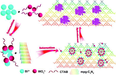
To our knowledge, there are no reports on the application and preparation of mpg-C3N4/Bi2WO6 (CNBW) composites. Herein, we report the synthesis of CNBW composites by oriented ultrathin nanoplates (∼12 nm) of Bi2WO6 via a facile hydrothermal method as shown in Scheme 1. We used CTAB as a surfactant to promote the formation of nest-like structures of Bi2WO6. Due to the electrostatic force, the positively charged CTA+ and the negatively charged WO42− attract each other to form a more stable intermediate product. In this way, the formation rate of Bi2WO6 nanoparticles is reduced. Due to the anisotropic growth of Bi2WO6, the zero dimensional (0D) nanoparticles can be transformed into two dimensional (2D) nanosheets. With the increase of reaction time, the nanosheets will be changed to three-dimensional (3D) nest-like structures because of self assembly. The visible-light photocatalytic activities are evaluated sufficiently with the degradation of the model dye and the antibiotics, demonstrating that the composites exhibit much improved photocatalytic activity than bare mpg-C3N4 and Bi2WO6. In addition, this work may also provide a useful method for the synthesis of the composite photocatalyst with enhanced photocatalytic performance.
2. Experimental
2.1. Synthesis of photocatalysts
2.2. Characterization of the photocatalysts
X-ray powder diffraction (XRD) spectra were obtained on Shimadzu XRD-6000 diffractometer with Cu Kα (λ = 1.5418 Å) as source in the range of 2θ = 10–80° at a scan rate of 0.1167° s−1. Fourier transform infrared (FT-IR) spectra were recorded on Nicolet FT-IR spectrometer (Nexus 470, Thermo Electron Corporation). X-ray photoelectron spectroscopy (XPS) measurements were performed on a ESCALab MKII spectrometer with Mg Kα radiation at 20 kV. The N2-sorption measurements were performed on Micromeritics Tristar 3000 at 77.35 K. The field-emission scanning electron microscopy (FE-SEM) and energy-dispersive X-ray spectroscope measurements were carried out with a field-emission scanning electron microscope (JEOL JSM-7001F) operating at an acceleration voltage of 10 kV. Transmission electron microscopy (TEM) analyses were performed by a JEOL-JEM-2010 spectrometer (JEOL, Japan) operating at 200 kV. Atomic force microscopy (AFM) images were obtained by FM-Nanoview 6800 AFM. The photoabsorption performance was characterized by a ultraviolet-visible (UV-vis) diffuse reflection spectroscopy (DRS, Shimadzu UV-2450, Japan), and BaSO4 was utilized as the standard material. The specific surface area (SSA) and the pore size distribution (PSD) were determined by Micromeritics Instrument, respectively. All the spectra have been normalized to the incident beam. Electron spin resonance (ESR) patterns were recorded on a Bruker model ESR JES-FA200 spectrometer in methanol and water, respectively.2.3. Photocatalytic performance measurement
Photocatalytic performance of the CNBW composite samples was determined in an opening quartz chamber (50 mL) by the decomposition of TC and RhB under simulated solar light of a 300 W Xe lamp with a 420 nm cut off filter. The irradiation area was ca. 25 cm2. Reaction conditions: temperature, 25 ± 0.5 °C; C0(TC) = 50 mg L−1; C0(RhB) = 20 mg L−1; C(CNBW) = 0.5 g L−1. Prior to irradiation, the solution was stirred under atmosphere for 30 min in darkness to achieve adsorption–desorption equilibrium. TC and RhB solution were collected, centrifuged and analyzed using UV-vis spectrometer (UV-2450, Shimadzu Ltd.) at wavelength 356 nm and 553 nm, respectively. The degradation efficiency (η) was determined using η (%) = (1 − C/C0) × 100%, where C0 represents the original solution concentration after achieving pollution-photocatalyst equilibrium and C was the concentration after reaction for time t.To investigate the active species produced in the photodegradation process of photocatalytic, hydroxyl radicals (·OH), superoxide radical (·O2−) and holes (h+) were probed by adding 5 mM tert-butyl alcohol (t-butanol), N2 and EDTA-2Na, respectively.38–40
2.4. Photoelectrochemical measurements
Electrochemical measurements were preformed with a CHI 660B (Chenhua Instrument Company, Shanghai, China) electrochemical workstation, using a three-electrode system. A platinum plate electrode and an Ag/AgCl electrode (3 M KCl) were used as counter electrode and reference electrode, respectively. The working electrode was photocatalyst (0.1 mg) films coated on ITO (0.5 × 1 cm2). The electrolyte was 0.1 M Na2SO4 solution and the photocurrent measurement were performed under visible light from a 500 W Xe lamp with 420 nm cutoff filters. The electrochemical impedance spectroscopy (EIS) measurements were recorded in 5 mM K3Fe(CN)6/K4Fe(CN)6 (1![[thin space (1/6-em)]](https://www.rsc.org/images/entities/char_2009.gif) :
:![[thin space (1/6-em)]](https://www.rsc.org/images/entities/char_2009.gif) 1) containing 0.1 mol L−1 KCl.
1) containing 0.1 mol L−1 KCl.
3. Results and discussion
3.1. Compositional and structural information
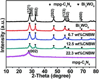
In order to correlate the photocatalytic performance of the as-synthesized CNBW photocatalysts with their structural performances, the CNBW samples are characterized by XRD, FT-IR and XPS in detail.The crystal structure of the CNBW samples is rated by XRD analysis, as shown in Fig. 1 and S1.† For the mpg-C3N4, the characteristic peak located at 27.5° indicated the diffraction interplanar staking peak of the aromatic conjugated system, which can be indexed to the (002) crystal plane (JCPDS no. 87-1526).29 For the Bi2WO6, the distinct diffraction peaks at 28.3°, 32.8°, 32.9°, 47.1°, 56.0°, 58.5°, and 68.8° corresponding to the (131), (200), (002), (202), (133), (262) and (400) crystallographic planes (JCPDS no. 39-0256), respectively.41 No impurity is found in CNBW samples. Furthermore, no mpg-C3N4 phase is observed in CNBW samples, which may be due to the restrictions on the use of mpg-C3N4 and high dispersion in CNBW samples. In addition, the sole peak of mpg-C3N4 overlaps with one of the Bi2WO6 peaks, which can be the reason that it cannot be discern clearly in the composites.
The chemical bonding and composition information of CNBW are further characterized by FT-IR analysis (Fig. S1†). In FT-IR spectrum of mpg-C3N4, a series of the peaks located between 1200 cm−1 to 1750 cm−1 conformed to the stretching vibration modes of the mpg-C3N4 heterocycles, while the sharp band located at 812 cm−1 is due to the breathing vibration of triazine ring in mpg-C3N4.42 In addition, the stretching vibrations of C–H can be observed at 2921 cm−1 and 2972 cm−1, possibly due to the existence of few CTAB.43 The absorption peaks at 571 cm−1, 736 cm−1 and 1380 cm−1 are owing to Bi–O, W–O stretching and W–O–W bridging stretching modes, suggesting the presence of the Bi2WO6.
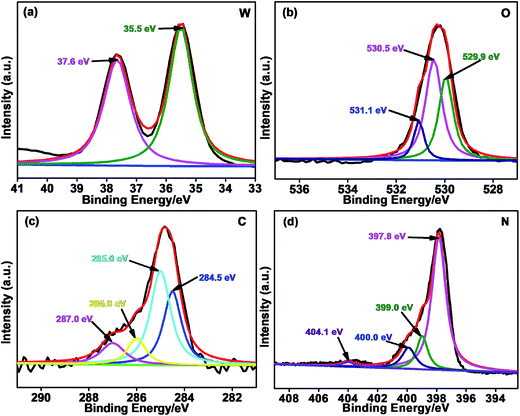
To analyze the surface chemical conditions of the Bi, W, O, C and N elements in the 12.5 wt% CNBW nanohybrid as shown in Fig. S2a,† XPS measurements were conducted (Fig. 2 and S2†). As shown in Fig. S2b,† the binding energies of Bi 4f7/2 and Bi 4f5/2 peaks are at approximate 159.2 and 164.6 eV, which is assigned to Bi3+ in crystal structure, respectively.41,44 In the W 4f spectra (Fig. 2a), peaks at 35.5 and 37.6 eV were ascribed to W 4f7/2 and W 4f5/2 of W6+ oxidation state,19,41 respectively. Three main peaks of O 1s at 529.9, 530.5 and 531.1 eV are assigned to the Bi–O, W–O and H–O on the surface of Bi2WO6,27 respectively, which are shown in Fig. 2b. In Fig. 2c, the C 1s peaks of the sample centered at ca. 284.5, 285.0, 286.0 and 287.0 eV. The peak at ca. 284.5 eV is graphite carbon, but the peak at around 285.0 eV is ascribable to C–O species.45 The binding energy centered at 286.0 and 287.0 eV correlated with the sp2-hybridized bonds in N–C![[double bond, length as m-dash]](https://www.rsc.org/images/entities/char_e001.gif) N and O–C
N and O–C![[double bond, length as m-dash]](https://www.rsc.org/images/entities/char_e001.gif) O,45,46 respectively. The broad N 1s peak of mpg-C3N4 in the spectrum is deconvoluted into four peaks centered at ca. 397.8, 399.0, 400.0 and 404.1 eV (Fig. 2d), which can be ascribed to pyridinic nitrogen, tertiary nitrogen (N–C3), amino functions (N–H), and the charging effects,47 respectively.
O,45,46 respectively. The broad N 1s peak of mpg-C3N4 in the spectrum is deconvoluted into four peaks centered at ca. 397.8, 399.0, 400.0 and 404.1 eV (Fig. 2d), which can be ascribed to pyridinic nitrogen, tertiary nitrogen (N–C3), amino functions (N–H), and the charging effects,47 respectively.
3.2. Morphology and textural property
The FE-SEM and EDS images of the as-prepared samples are presented in Fig. 3. As shown in Fig. 3a and b, all the pure Bi2WO6 products have a nest-like morphology, with diameters ranging from 2 to 4 μm. In Fig. 3c, the FE-SEM image of mpg-C3N4 presents a typical multihole layered structure of the graphitic mesoporous of carbon nitride. Nevertheless, the microstructures of the 12.5 wt% CNBW composite (Fig. 3d and e) are found the nest-like structure intermingled with multihole stacking structure. The contact region between mpg-C3N4 and Bi2WO6 may enhance the photo-excited carrier separation rate. Moreover, the EDS pattern (Fig. 3f) indicates that the 12.5 wt% CNBW composite contains C, N, O, W and Bi elements, which is in accordance with the XPS results. In Fig. S3,† the mapping results reveal that the C (b) and N (c) elements are uniformly distributed in 12.5 wt% CNBW nanocomposite and that the O (d), Bi (e) and W (f) elements are dispersed like microspheres in the 12.5 wt% CNBW samples.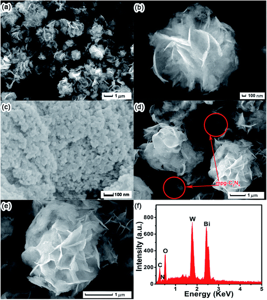 | ||
| Fig. 3 FE-SEM images of Bi2WO6 (a and b), mpg-C3N4 (c), 12.5 wt% CNBW composite (d and e); EDS (f) of the 12.5 wt% CNBW composite. | ||
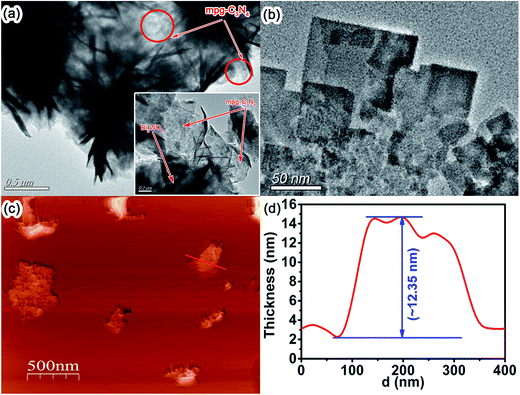
TEM and AFM are used to further analyze the microstructure of CNBW composite, as shown in Fig. 4. Fig. 4a is the TEM image of 12.5 wt% CNBW, it can be clearly seen that Bi2WO6 is a nest-like structure composed of thin sheets, as well as the nest-like structure of Bi2WO6 is anchored on the mesoporous structure of surface mpg-C3N4. Concurrently, few peeled fragments can also be found, which further evidences the Bi2WO6 thin films, as indicated in Fig. 4b. We further investigate the thickness of Bi2WO6 sheet by AFM, which show that the thickness of Bi2WO6 is around 12 nm (ref. 48) (Fig. 4c and d). It can greatly improve the photocatalytic activity by reducing the bulk recombination rate, because ultrathin thickness can make photo-excited carrier easily transferring to the surface from the interior.23,24,49
Fig. S4† depicts the N2 adsorption–desorption pattern and the homologous pore size distribution curves for mpg-C3N4, Bi2WO6 and CNBW samples. It can be seen that specific surface area (SSA) of mpg-C3N4, Bi2WO6, 6.7 wt% CNBW, 12.5 wt% CNBW and 22.3 wt% CNBW samples are about 128.4, 27.9, 37.6, 40.2, 43.5 m2 g−1, respectively. In theory, the high porosity of mpg-C3N4 constructed herein can result in large surface areas and greater numbers of active sites for various application-driven photocatalyses.10 Fig. S4,† the isotherms are type IV with a H3 hysteresis loop in the scope of 0.65–1.00 P/P0, which can be also indicated by its pore-size distribution and suggested there are both mesopores and micropores. It also shows that the increase of Bi2WO6 did not significantly change or block the pore structure of mpg-C3N4. The improved surface area is favorable for the adsorption of more reactants and active substances, so as to improve the photocatalytic activity.
3.3. Optical and electronic properties
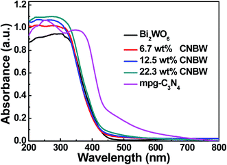
The light absorption behaviors of Bi2WO6, mpg-C3N4 and CNBW photocatalysts are probed by optical diffuse-reflection spectra (DRS), and the result is depicted in Fig. 5. The absorption edges of pure mpg-C3N4 and Bi2WO6 photocatalysts are around 450 and 445 nm, corresponding band gap (Eg) calculated to be 2.7 (ref. 9) and 2.8 eV,19,22 respectively. Combining mpg-C3N4 and Bi2WO6 caused a redshift in the absorption edges with increasing the mass ratio of mpg-C3N4 and Bi2WO6, improving the absorption in the light range of visible, and indicating that all the CNBW composites possessed visible light response. The enhanced optical absorption may result in the generation of more photogenerated carriers, thereby enhancing the photocatalytic activity.It is well-known that the photocurrent is widely considered as the reliable testimony to prove the separation efficiency of the photogenerated electron–hole pairs in the semiconductor photocatalysis process. The photogenerated current measurements of Bi2WO6, mpg-C3N4, and 12.5 wt% CNBW samples are performed, it can be clearly detected that the transient photocurrent of CNBW is about 3.5 times higher than that of the Bi2WO6 and mpg-C3N4, as shown in Fig. 6a. This displays that the electrodes are stable and the photosensitivity is completely reversible. This result supported that more efficient transportation and separation of the photogenerated electron–hole pairs are realized, which can be attributed to the heterostructure built between mpg-C3N4 and Bi2WO6.
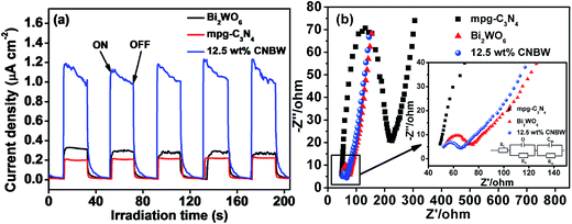 | ||
| Fig. 6 Transient photocurrent responses (a) and electrochemical impedance spectroscopy (b) of Bi2WO6, mpg-C3N4 and 12.5 wt% CNBW under visible light irradiation. | ||
To assess the charge-transfer and recombined process at semiconductor–electrolyte interfaces, the EIS is performed. Fig. 6b indicates that the CNBW Nyquist plot diameter is much smaller than Bi2WO6 and mpg-C3N4, suggesting that interfacial charge transfer is faster and low resistance. It also means that the separation and transmission rate of photogenerated electrons are elevated significantly via interfacial interaction between mpg-C3N4 and Bi2WO6.
3.4. Photocatalytic tests
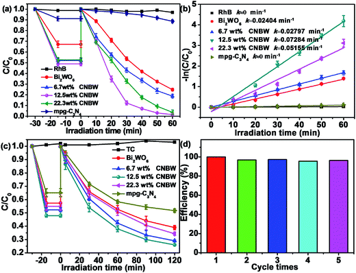
The photocatalytic performance of Bi2WO6, mpg-C3N4 and CNBW samples with different mass ratios are evaluated by 20 mg L−1 RhB degradation under visible light (λ > 420 nm). Fig. 7 displays the standard concentration of RhB illumination time for photocatalytic degradation under visible light irradiation. The blank experiment proves the RhB is stable in the lack of photocatalysts, suggesting that the degradation of RhB can be negligible. Among the photocatalysts tested, the CNBW composites exhibited higher photocatalytic performance than Bi2WO6 and mpg-C3N4, and the photocatalytic activity of CNBW is enhanced with the increase of mpg-C3N4 ratio, as shown in Fig. 7a. But further increase in the amount of mpg-C3N4 causes a rapid decrease in photocatalytic activity, which may be due to excessive mpg-C3N4 coverage in the surface confined CNBW. Moreover, 12.5 wt% CNBW shows the best photocatalytic performance, the photocatalytic degradation of 20 mg L−1 RhB achieves 100% within 60 min. Fig. S5† shows the instantaneous evolution of the absorption spectra during the degradation of RhB in the existence of the 12.5 wt% CNBW samples, indicating the excellent photocatalytic activity. At the same time, the photocatalytic reaction kinetics of RhB by using CNBW composites is also evaluated, and the results are displayed in Fig. 7b. As we can see, the degradation rate of 12.5 wt% CNBW is determined to be 0.07284 min−1, which is approximately 3 times higher than that of Bi2WO6 (0.02404 min−1) and much larger than that of mpg-C3N4 (0 min−1).The broad-spectrum antibiotic, TC, is widely utilized for combating microbial infections. TC may cause adverse effects on ecosystems in nature, so it is important to remove TC.50,51 TC is slowly photodegraded in the existence of Bi2WO6 or mpg-C3N4 under visible light; however, the photocatalytic activity is enhanced remarkably after a marriage of mpg-C3N4 and Bi2WO6. True to form, 12.5 wt% CNBW shows the best photocatalytic performance, and the photocatalytic degradation of TC attains 75% within 120 min (Fig. 7c). Hence, the composite helps to improve the photocatalytic efficiency under visible light.
The regeneration and reusability of the 12.5 wt% CNBW composite is analyzed for RhB degradation by performing recycling experiments under visible light. As can be seen from Fig. 7d, after five consecutive cycles, there is no significant change in the photocatalytic activity, illustrating the high durability of the photocatalyst under visible light. XRD spectra not only show that the crystalline information of photocatalyst has not changed during the photocatalysis process, but also clearly indicate that the photocatalyst is very stable (Fig. S6†). Based on the above results, we conjecture that the interaction between mpg-C3N4 and Bi2WO6 promotes the formation of the efficient and stable CNBW photocatalyst.
3.5. Mechanism of pollutant photodegradation
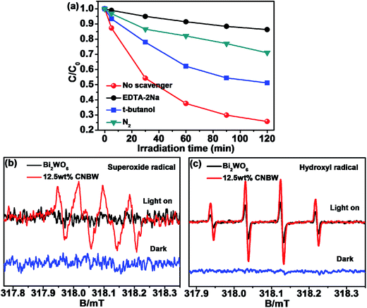
In order to further investigate the catalytic mechanism, the active species formed during the reaction are identified by the trapping experiment of radicals in TC photodegradation over 12.5 wt% CNBW (Fig. 8a). The EDTA-2Na, t-butanol and N2 are used as h+, ·OH and ·O2− scavengers,38–40 respectively. The photocatalytic activity is greatly inhibited when EDTA is added, which means that h+ plays an important role in the photocatalytic degradation of TC. Similarly, after the addition of N2 and t-butanol, the photocatalytic rate is greatly reduced, which indicates that ·O2− and ·OH also play an important role in the photocatalytic process. Therefore, h+, ·O2− and ·OH are the primary active species.The ESR spectroscopy with DMPO spin-trapping adducts allows the observation of superoxide radical (DMPO–·O2−) and hydroxyl radical (DMPO–·OH) during the irradiation of 12.5 wt% CNBW.52 As indicated in Fig. 8, six characteristic peaks of DMPO–·O2− spin-trapping adducts are obviously detected under visible light illumination (Fig. 8b), and four characteristic peaks of DMPO–·OH signals can also be detected (Fig. 8c). In addition, no DMPO–·O2− signals are found in Bi2WO6 and the peak intensity of DMPO–·OH adducts of CNBW is distinctively higher than that of Bi2WO6, which is due to the synergistic effect of mpg-C3N4 and Bi2WO6. These results are agree with the trapping experiment results, which show that h+, ·O2− and ·OH are the main active species in the photocatalysis degradation process.
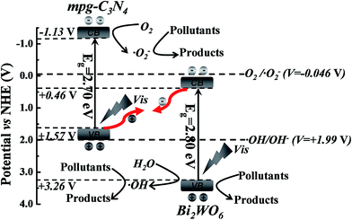
Based on the aforementioned experimental results and related literature, we propose the possible Z-scheme mechanism of CNBW to enhance the photocatalytic performance by increasing the separation efficiency of photogenerated electron–hole pairs at the surface of heterostructure under visible light (Fig. 9). The conduction band minimum (CBM) and valence band maximum (VBM) positions of mpg-C3N4 are ca. −1.13 V and +1.57 V, respectively,53 while those of Bi2WO6 are about +0.46 V and +3.26 V, respectively.54 Both mpg-C3N4 and Bi2WO6 can be used to generate electron–hole pairs under visible light. Then, the photogenerated electrons in the CBM of Bi2WO6 can recombine the holes in the VBM of mpg-C3N4 at the interface of the heterostructure.55 It can accumulate more reductive electrons and oxidative holes to involve in the redox reactions, resulting in high photocatalytic efficiency. Consequently, the strong reductive electrons can reduce oxygen in the air to generate ·O2−, because the CBM edge potential of mpg-C3N4 is more negative than that of O2/·O2− (−0.046 V),56 and superoxide radical can further induce the mineralization of organic pollutants. At the same time, the strong oxidizing holes in the Bi2WO6 interface can also degrade organic pollutants. Furthermore, the holes in the VBM of Bi2WO6 can oxidize H2O to ·OH because the VBM potential of Bi2WO6 is more positive than the potential of ·OH/OH− (+1.99 V), and then induced the organic pollutants degradation.56 Based on the above discussion, it can be seen that the band structure and the interaction of mpg-C3N4 and Bi2WO6 lead to the improvement of photocatalytic performance, and the CNBW system is a type of Z-scheme photocatalysis.
4. Conclusions
A novel mpg-C3N4/Bi2WO6 composite photocatalytic material is first prepared by a simple hydrothermal method. The composite photocatalytic materials show strong photocatalytic activity under visible light irradiation, which is notably higher than that of pristine mpg-C3N4 or Bi2WO6. The h+, ·O2− and ·OH are the main active species in the photocatalytic degradation process. Relied on the experimental results and theoretical analysis, the photocatalytic Z-scheme mechanism of the system was also discussed. The high photocatalytic performance is due to the high rate of photogenerated carrier separation. Furthermore, the ultrathin thickness of nest-like structure Bi2WO6 can make photo-excited carrier easily transferred to the surface from the interior, and therefore reduces the bulk reorganization. Such a strategy may give a good understanding of the development of other similar photocatalytic materials.Acknowledgements
This work was supported by National Nature Science Foundation of China (21476097), Six Talent Peaks project in Jiangsu Province (2014-JNHB-014), a project funded by the Priority Academic Program Development of Jiangsu Higher Education Institutions.References
- A. Kudo and Y. Miseki, Chem. Soc. Rev., 2009, 38, 253–278 RSC.
- Z. G. Zou, J. H. Ye, K. Sayama and H. Arakawa, Nature, 2001, 414, 625–627 CrossRef CAS PubMed.
- W. G. Tu, Y. Zhou and Z. G. Zou, Adv. Funct. Mater., 2013, 23, 4996–5008 CrossRef CAS.
- S. C. Yan, Z. S. Li and Z. G. Zou, Langmuir, 2009, 25, 10397–10401 CrossRef CAS PubMed.
- H. Xu, J. Yan, Y. G. Xu, Y. H. Song, H. M. Li, J. X. Xia, C. J. Huang and H. L. Wan, Appl. Catal., B, 2013, 129, 182–193 CrossRef CAS.
- Y. Zheng, Y. Jiao, J. Chen, J. Liu, J. Liang, A. Du, W. M. Zhang, Z. H. Zhu, S. C. Smith, M. Jaroniec, G. Q. Lu and S. Z. Qiao, J. Am. Chem. Soc., 2011, 133, 20116–20119 CrossRef CAS PubMed.
- X. C. Wang, K. Maeda, A. Thomas, K. Takanabe, G. Xin, J. M. Carlsson, K. Domen and M. Antonietti, Nat. Mater., 2009, 8, 76–80 CrossRef CAS PubMed.
- X. D. Zhang, X. Xie, H. Wang, J. J. Zhang, B. C. Pan and Y. Xie, J. Am. Chem. Soc., 2012, 135, 18–21 CrossRef PubMed.
- Y. M. He, J. Cai, L. H. Zhang, X. X. Wang, H. J. Lin, B. T. Teng, L. H. Zhao, W. Z. Weng, H. L. Wan and M. H. Fan, Ind. Eng. Chem. Res., 2014, 53, 5905–5915 CrossRef CAS.
- W. J. Ong, L. L. Tan, Y. H. Ng, S. T. Yong and S. P. Chai, Chem. Rev., 2016, 116, 7159–7329 CrossRef CAS PubMed.
- G. H. Tian, Y. J. Chen, W. Zhou, K. Pan, Y. Z. Dong, C. G. Tian and H. G. Fu, J. Mater. Chem., 2013, 21, 887–892 RSC.
- Y. H. Ng, A. Iwase, A. Kudo and R. Amal, J. Phys. Chem. Lett., 2010, 1, 2607–2612 CrossRef CAS.
- A. Kudo, K. Omori and H. Kato, J. Am. Chem. Soc., 1999, 121, 11459–11467 CrossRef CAS.
- Z. J. Zhang, W. Z. Wang, L. Wang and S. M. Sun, ACS Appl. Mater. Interfaces, 2012, 4, 593–597 CAS.
- J. Y. Xiong, G. Cheng, G. F. Li, F. Qin and R. Chen, RSC Adv., 2011, 1, 1542–1553 RSC.
- Y. N. Huo, J. Zhang, M. Miao and Y. Jin, Appl. Catal., B, 2012, 111, 334–341 CrossRef.
- Y. Y. Li, J. S. Wang, H. C. Yao, L. Y. Dang and Z. J. Li, J. Mol. Catal. A: Chem., 2011, 334, 116–122 CrossRef CAS.
- Z. F. Bian, J. Zhu, S. H. Wang, Y. Cao, X. F. Qian and H. X. Li, J. Phys. Chem. C, 2008, 112, 6258–6262 CAS.
- C. Zhang and Y. F. Zhu, Chem. Mater., 2005, 17, 3537–3545 CrossRef CAS.
- M. R. Hoffmann, S. T. Martin, W. Choi and D. W. Bahemann, Chem. Rev., 1995, 95, 69–96 CrossRef CAS.
- L. S. Zhang, W. Z. Wang, Z. G. Chen, L. Zhou, H. L. Xua and W. Zhu, J. Mater. Chem., 2007, 17, 2526–2532 RSC.
- Z. J. Zhang, W. Z. Wang, L. Wang and S. M. Sun, ACS Appl. Mater. Interfaces, 2012, 4, 593–597 CAS.
- R. I. Bickley, T. GonzAlez-Carrefio, L. Palmisano, R. J. D. Tilley and J. M. Williams, Mater. Chem. Phys., 1997, 51, 47–53 CrossRef CAS.
- L. Liang, F. C. Lei, S. Gao, Y. F. Sun, X. C. Jiao, J. Wu, S. Qamar and Y. Xie, Angew. Chem., Int. Ed., 2015, 54, 13971–13974 CrossRef CAS PubMed.
- L. Liu, Y. Wang, W. An, J. Hu, W. Cui and Y. Liang, J. Mol. Catal. A: Chem., 2014, 394, 309–315 CrossRef CAS.
- J. Ren, W. Z. Wang, S. M. Sun, L. Zhang and J. Chang, Appl. Catal., B, 2009, 92, 50–55 CrossRef CAS.
- L. Liu, Y. H. Qi, J. R. Lu, S. L. Lin, W. J. An, J. S. Hu, Y. H. Liang and W. Q. Cui, RSC Adv., 2015, 5, 99339–99346 RSC.
- X. C. Wang, K. Maeda, A. Thomas, K. Takanabe, G. Xin, J. M. Carlsson, K. Domen and M. Antonietti, Nat. Mater., 2009, 8, 76–80 CrossRef CAS PubMed.
- X. C. Wang, K. Maeda, X. F. Chen, K. Takanabe, K. Domen, K. Domen, Y. D. Hou, X. Z. Fu and M. Antonietti, J. Am. Chem. Soc., 2009, 131, 1680–1681 CrossRef CAS PubMed.
- Y. J. Wang, R. Shi, J. Lin and Y. F. Zhu, Energy Environ. Sci., 2011, 4, 2922–2929 CAS.
- G. Q. Tan, L. N. She, T. Liu, C. Xu, H. J. Ren and A. Xia, Appl. Catal., B, 2017, 207, 120–133 CrossRef CAS.
- Y. L. Tian, B. B. Chang, J. L. Lu, J. Fu, F. N. Xi and X. P. Dong, ACS Appl. Mater. Interfaces, 2013, 5, 7079–7085 CAS.
- Y. J. Wang, X. J. Bai, C. S. Pan, J. He and Y. F. Zhu, J. Mater. Chem., 2012, 22, 11568–11573 RSC.
- F. Goettmann, A. Fischer, M. Antonietti and A. Thomas, Angew. Chem., Int. Ed., 2006, 45, 4467–4471 CrossRef CAS PubMed.
- J. Xu, H. T. Wu, X. Wang, B. Xue, Y. X. Li and Y. Cao, Phys. Chem. Chem. Phys., 2013, 15, 4510–4517 RSC.
- J. S. Zhang, M. W. Zhang, C. Yang and X. C. Wang, Adv. Mater., 2014, 26, 4121–4126 CrossRef CAS PubMed.
- X. F. Chen, Y. S. Jun, K. Takanabe, K. Maeda, K. Domen, X. Z. Fu, M. Antonietti and X. C. Wang, Chem. Mater., 2009, 21, 4093–4095 CrossRef CAS.
- L. Q. Ye, J. Y. Liu, C. Q. Gong, L. H. Tian, T. Y. Peng and L. Zan, ACS Catal., 2012, 2, 1677–1683 CrossRef CAS.
- H. W. Huang, K. Liu, K. Chen, Y. L. Zhang, Y. H. Zhang and S. C. Wang, J. Phys. Chem. C, 2014, 118, 14379–14387 CAS.
- T. G. Xu, L. W. Zhang, H. Y. Cheng and Y. F. Zhu, Appl. Catal., B, 2011, 101, 382–387 CrossRef CAS.
- J. Di, J. X. Xia, Y. P. Ge, H. P. Li, H. Y. Ji, H. Xu, Q. Zhang, H. M. Li and M. N. Li, Appl. Catal., B, 2015, 168, 51–61 CrossRef.
- S. K. Le, T. S. Jiang, Y. W. Li, Q. Zhao, Y. Y. Li, W. B. Fang and M. Gong, Appl. Catal., B, 2017, 200, 601–610 CrossRef CAS.
- H. B. Li, G. C. Liu and X. C. Duan, Mater. Chem. Phys., 2009, 115, 9–13 CrossRef CAS.
- X. M. Tu, S. L. Luo, G. X. Chen and J. H. Li, Chem.–Eur. J., 2012, 18, 14359–14366 CrossRef CAS PubMed.
- S. Kumar, A. Baruah, S. Tonda, B. Kumar, V. Shanker and B. Sreedhar, Nanoscale, 2014, 6, 4830–4842 RSC.
- H. J. Kong, H. W. Da, J. Kim and S. I. Woo, Chem. Mater., 2016, 28, 1318–1324 CrossRef CAS.
- S. B. Yang, X. L. Feng, X. C. Wang and K. Müllen, Angew. Chem., Int. Ed., 2011, 50, 5339–5343 CrossRef CAS PubMed.
- I. Horcas, R. Fernández, J. M. Gomez-Rodriguez and J. Colchero, Rev. Sci. Instrum., 2007, 78, 013705 CrossRef CAS PubMed.
- X. J. She, J. J. Wu, J. Zhong, H. Xu, Y. C. Yang, R. Vajtai, J. Lou, Y. Liu, D. L. Du, H. M. Li and P. M. Ajayan, Nano Energy, 2016, 27, 138–146 CrossRef CAS.
- J. C. Chee-Sanford, R. I. Aminov, I. J. Krapac, N. Garrigues-Jeanjean and R. I. Mackie, Appl. Environ. Microbiol., 2001, 67, 1494–1502 CrossRef CAS PubMed.
- J. Y. Liu, H. Xu, Y. G. Xu, Y. H. Song, J. B. Lian, Y. Zhao, L. Wang, L. Y. Huang, H. Y. Ji and H. M. Li, Appl. Catal., B, 2017, 207, 429–437 CrossRef CAS.
- Y. H. Lv, Y. Y. Zhu and Y. F. Zhu, J. Phys. Chem. C, 2013, 117, 18520–18528 CAS.
- L. Ge, C. C. Han and J. Liu, Appl. Catal., B, 2011, 108, 100–107 CrossRef.
- Z. J. Zhang, W. Z. Wang, L. Wang and S. M. Sun, ACS Appl. Mater. Interfaces, 2012, 4, 593 CAS.
- P. Zhou, J. G. Yu and M. Jaroniec, Adv. Mater., 2014, 26, 4920–4935 CrossRef CAS PubMed.
- B. Wang, J. Di, P. F. Zhang, J. X. Xia and S. Dai, Appl. Catal., B, 2017, 206, 127–135 CrossRef CAS.
Footnotes |
| † Electronic supplementary information (ESI) available. See DOI: 10.1039/c7ra06681c |
| ‡ Zhu and Liu are co-author. |
| This journal is © The Royal Society of Chemistry 2017 |

