 Open Access Article
Creative Commons Attribution 3.0 Unported Licence
Controllable synthesis of unique Ni/mesoporous carbon composites with lightweight and high EM wave absorption performance
Muyu Chena,
Haiyan Zhang *a,
Guoxun Zenga,
Danfeng Zhangb,
Chengjie Yana,
Yu Shena,
Xiaofen Yua,
Qibai Wua and
Yuanwu Chen*a
aSchool of Materials and Energy, Guangdong University of Technology, Guangzhou 510006, China. E-mail: ychenar@connect.ust.hk; hyzhang@gdut.edu.cn
bSchool of Computer Science and Technology, Guangdong University of Technology, Guangzhou 510006, China
First published on 7th August 2017
Abstract
In present work, Ni/disordered mesoporous carbon (DMC) composites with unique structure have been prepared through a proprietary two-step process combining the sol–gel preparation of DMC and the in situ reduction of Ni from co-precipitated nickel nitrate. Confirmed by scanning electron microscopy, transmission electron microscopy and X-ray diffraction, the Ni nanoparticles were found to be sparsely dispersed in the wormhole-like channel and the mesopores, acting as scattering centres that significantly intensified the electromagnetic (EM) wave multiple reflection and improved the dielectric loss through additional interfacial polarization. Evaluation of the EM absorption properties suggested that the reflection loss (RL) was noticeably reduced from −11.6 dB at 13 GHz to −27 dB at 9 GHz, and the frequency bandwidth corresponding to RL < −10 dB was broadened from about 1 GHz to over 4.5 GHz after incorporation of DMC with Ni. The experimental results show that Ni/DMC composites are superior to neat DMC so that they could be some of the most promising candidates for the new generation of EM absorption materials with improved performance and well-maintained lightweight feature.
1. Introduction
With the rapid development of wireless communication technology, the electromagnetic (EM) wave has been more and more extensively applied and emerged as one of the most serious pollutants in our surroundings. Various research groups have reported that long-term exposure to EM radiation without any protection may cause DNA damage and result in a higher probability of suffering from cancer.1 This increasingly grave situation has drawn more and more effort to the studies of EM absorbers in civilian applications. On the other hand, as the radar stealth technology of aircraft becomes more and more important against defensive reconnoitre, advanced EM absorption materials are also highly demanded in military applications.2 Ferrites, ceramics, magnetic metals and so on have been widely explored and utilized as EM absorption materials for a long time by dispersion in EM transparent matrixes.3–6 However, owing to the high density and high filler loading required, application of these traditional EM absorption materials are limited, especially in fields like aerospace that are extremely weight-sensitive. Therefore, it is of great momentum to find a new generation of EM absorption material.The ideal EM absorbing material should be light in weight but high in the EM absorption efficiency. Specifically, the one of low cost will be more competitive so that it could be widely accepted for civilian applications. Being a typical highly porous material that has been extensively applied in various areas like supercapacitor, sensitized electrode, fuel cell and so on,7–11 the mesoporous carbon (MC) has also attracted more and more attention with respect to the intense dielectric loss and was regarded as one of the most important candidates for the advanced EM absorption materials. Combining the pyrolysis-etching process with the Stöber templating approach, Xu et al.12 has prepared hollow mesoporous carbon with uniform pore size of about 4.7 nm. Owing to the highly porous structure that may have induced effective multiple-reflection of EM wave and improved the impedance matching, the paraffin composites of 3 mm showed minimum reflection loss (RL) of about 18.2 dB at 11.0 GHz and possessed typical broadband feature that the effective absorption bandwidth (RL < −10 dB) could be over 3.5 GHz.
Compared to other carbon materials like carbon nanotubes (CNTs) and carbon fibre (CF), the mesoporous carbon is well dispersed and the structure is customizable.13–15 More importantly, the dielectric and magnetic properties could be conveniently adjusted through structural design or decoration so as to obtain optimized performance.16 The study conducted by Wang17 has provided a valid point that both the pore size and the electromagnetic parameters (εr, μr) of ordered mesoporous carbon (OMC) could be conveniently regulated through hybrid with semi-conductive nano-TiO2, which herein lead to obvious improvement of the EM absorption properties due to the enhanced resonance dielectric loss. Alternatively, aiming to realize the synergistic EM absorption through multiple mechanisms (dielectric and magnetic), magnetic components like iron oxide,18,19 cobalt ferrite20 have been also introduced into the order mesoporous carbon. For example, Wu et al.21 synthesized the porous flower-like Fe2O3/OMC nanocomposites and proved that the Fe2O3 of special geometric morphology is favourable to both the microwave absorption efficiency and bandwidth.
However, incorporation of mesoporous carbon with magnetic metal has been rarely reported so far. Furthermore, most of the studies were carried out based on the ordered mesoporous carbon; of which additional ordered mesoporous silica was indispensably required as the hard template during the preparation process and made the products more costly. Whereat, previous work of our research group has established a facile sol–gel method for preparation of disordered mesoporous carbon and found that the disordered mesoporous carbon probably attenuated the EM wave energy in a distinctive way.22 In present research, the common seen magnetic metal nickel (Ni) was further introduced through co-precipitation followed by in situ reduction. As per the specially designed two-steps synthesis as shown in Fig. 1, the effects of Ni on the structure and electromagnetic properties of Ni/DMC composites will be investigated in detail and the possible mechanism will be discussed.
2. Experimental section
2.1 Synthesis of DMC
Preparation of disordered mesoporous carbon materials was conducted in the sol–gel method as described in our previous publication.22 Typically, 60 g sucrose was firstly dissolved in 100 mL sulfuric acid (1 mol L−1) and 150 mL tetraethoxysilane (TEOS) was added. After magnetically stirred for about 2 hours, a clear solution was obtained and transferred to a polypropylene (PP) vessel, followed by introduction of 12.87 mL of 4% hydrofluoric acid (HF). After that, the mixture was enabled to react at 60 °C for 36 hours, and then the reactant was transferred back to a glass vessel for thermal treatment under 100 °C and 160 °C for 8 hours, respectively. Finally, the bright black gel obtained was carbonized in a tubular furnace at 900 °C for 3 hours under nitrogen (N2) atmosphere. After removal of silica with HF acid and vacuum drying under 100 °C for 8 hours, the DMC in black powder can be obtained.2.2 Preparation of magnetic Ni/DMC composites
With the as synthesized DMC as precursor, the Ni/DMC composites were prepared through a co-precipitation method. Firstly, 3 g of the as prepared DMC was homogeneously dispersed in deionized water with various amount of nickel nitrate pre-dissolved. The suspension was magnetically stirred under 50 °C water bath for 2 hours. After slowly introducing excessive amount of NaOH, the suspension was further stirred for another 2 hours at ambient temperature and 6 hours at 70 °C consecutively. The suspension was then centrifuged and extensively washed with deionized water. Under nitrogen atmosphere, the precipitate was calcined in a tubular furnace at 800 °C for 3 h, and the obtained product was denoted as Ni/DMC (3 − x), in which x is the amount of added nickel nitrate corresponding to 3 g of DMC.2.3 Characterization and measurement
The morphology of DMC and Ni/DMC composites was directly observed with a S3400N scanning electron microscope (Hitachi, Japan) and a JEM-2100F transmission electron microscope (JEOL, Japan), while the composition was confirmed through energy dispersive X-ray (EDX) spectrometry and X-ray powder diffraction (D/max-Ultima IV, Rigaku). The quantitative analysis was further conducted in which Ni was selectively dissolved by dispersing the Ni/DMC composites in HCl solution and the weight loss was calculated after filtration and drying. Using a Micromeritics ASAP 2020, the Barrett–Joyner–Halenda (BJH) pore size distribution and Brunauer–Emmett–Teller (BET) specific surface area were measured through nitrogen adsorption/desorption method.The magnetic properties characterizations were carried out with a Vibrating Sample Magnetometer (VSM) at room temperature. The relative permittivity εr and permeability μr were obtained on an AV3618 Network Analyser in the EM wave frequency range of 2 to 18 GHz for calculation of reflection loss (RL) via the coaxial reflection/transmission method. For the EM measurement, the powder samples were homogeneously mixed with paraffin at the loading of 30% by weight, and then the paraffin composites were pressed into toroidal shape samples (7 mm in outer diameter and 3.04 mm in inner diameter) with thickness of 2–3 mm.
3. Results and discussion
3.1 Morphology and structure
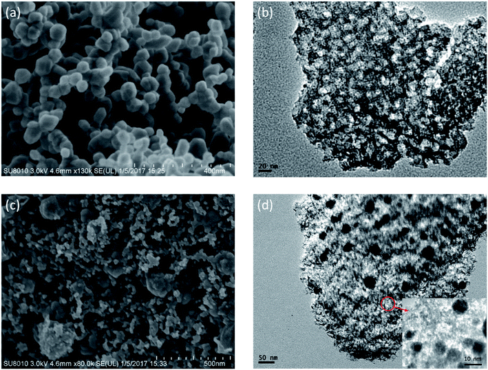
In the two-step synthesis of highly porous complex with magnetic particle, DMC prepared through the facile sol–gel method has been utilized as the matrix where Ni nanoparticle was introduced. The morphology and structure of the obtained DMC was characterized through electron microscopes as shown in Fig. 2. As illustrated by the SEM images Fig. 2(a), the obtained DMC is composed with uniform particles of mostly 30–50 nm. Frames of the carbon particles have formed irregular pores connecting with each other and resulted in unique disordered 3D channels consequently. Meanwhile, a further investigation through the high resolution TEM (Fig. 2(b)) suggested that there were mesopores of about 10 nm in each individual particle. According to the above result, it can be clearly identified that the as prepared DMC through sol–gel method is highly porous. The nitrogen adsorption/desorption isotherm was carried out to have an in-depth understanding about the porous structure. As shown in Fig. 3, the plot for DMC exhibit type IV isotherm with a hysteresis loop, indicating the typical adsorption of mesoporous materials. In line with the observation from TEM images, the pore size calculated possesses narrow Gaussian distribution that centres at about 12.7 nm and a tremendous specific area up to 600 m2 g−1 can be obtained.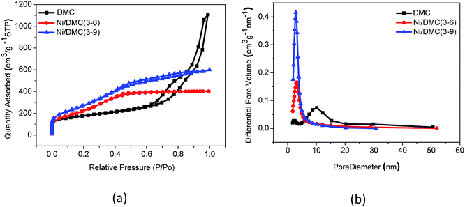 | ||
| Fig. 3 Nitrogen adsorption/desorption isotherms (a) and pore size distributions (b) of DMC and Ni/DMC composites. | ||
Taking the highly porous DMC as the precursor, co-precipitation of nickel salt followed by in situ reduction has been innovated to prepare the Ni/DMC composites in present work. The compositional variation during the process was confirmed by the XRD pattern as sketched in Fig. 4(a). Different from the one of neat DMC that only presented a very broad diffusion at about 23°, a pattern comprised of a series of peaks at 19.0°, 33.1°, 38.4°, 51.8°, 59.1°, 62.6°, 69.5° and 72.7° was obtained for the precipitant after introduction of NaOH, according to which the intermediate product was postulated to be Ni(OH)2/DMC.23 When the porous Ni(OH)2/DMC underwent the thermal reduction under N2 atmosphere, the variation of XRD pattern suggest that Ni was obtained as the characteristic peaks at 44.5°, 51.8° and 76.4° are definitely assigned to the diffraction of (111), (200) and (220) planes. With increase of the initial nickel nitrate concentration, the intensity of the Ni diffraction peaks increased as a higher content has been obtained according to the quantification result as shown in Table 1. Besides, no other foreign peak in the graph was found, indicating that the purity of the in-site generated Ni was quite high after reduction.
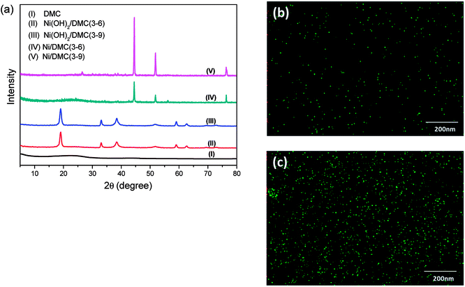 | ||
| Fig. 4 Compositional variation during the preparation of Ni/DMC composites confirmed by XRD (a) and elemental mapping of Ni, (b) for Ni/DMC (3–6) and (c) for Ni/DMC (3–9). | ||
| Sample | Ni content (wt%) | Pore size (nm) | Specific area (m2 g−1) | Ms (emu g−1) |
|---|---|---|---|---|
| DMC | 0% | 12.7 | 600 | 1.4 |
| Ni/DMC (3–6) | 26.4% | 3.6 | 822 | 19.3 |
| Ni/DMC (3–9) | 32.6% | 3.3 | 1152 | 21.0 |
The morphology of the Ni/DMC composites was verified by SEM and TEM. Originating from the DMC skeleton, the obtained magnetic composites are of analogous structure except some minor differences as shown in Fig. 2(c) and (d). Firstly and most importantly, it can be seen that there are a lot of black particles presumed to be Ni, sparsely dispersing in the mesopores (as revealed in the enlarge picture) and wormhole-like 3D channel with diameters from several to tens nanometres. Applying the energy dispersive X-ray spectrometry, this was clearly affirmed by the elemental distributions shown in Fig. 4(b) and (c). What should be pointed out is that the existence of Ni nanoparticle in the mesopores of DMC is only realizable through the 2-step process, which otherwise would be completely embedded in the wall according to our experience. Minor variation of the microporous structure after introducing the Ni nanoparticle was also detected, which led to deviation of nitrogen adsorption/desorption isotherm behaviours although they still possessed type IV with a hysteresis loops as shown in Fig. 3. Depending on the Ni content, the pore size was reduced to about 3 nm as summarized in Table 1, and the specific area was also improved to more than 1152 m2 g−1 for Ni/DMC (3–9). This can be reasonably explained as the mesopores have been partially occupied and tremendous interface emerged between Ni nanoparticle and the wall of DMC mesopores. Meanwhile, with regard to the larger uptake at P/P0 < 0.01 for the isotherms of Ni/DMC composites, this can be also attributed to generation of additional microspores, which was catalysed by Ni nanoparticle during the thermal reduction process at high temperature.24
3.2 Electromagnetic characteristics
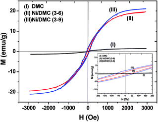
As mentioned above, Ni nanoparticles were introduced after in situ reduction of nickel salt that was previously co-precipitated at the presence of DMC. Presumably, the variation of both composition and structure would bring change in the magnetic properties of DMC. Fig. 5 shows the magnetization (M) as a function of the applied magnetic field (H) for Ni/DMC composites. The plots display typical S-profiles, while the appearance of hysteresis loops confirms the ferromagnetic property that originally stems from the existence of Ni nanoparticles. With increase of the nickel content, both the saturation magnetization (Ms) and coercive force (Hc) increase and reach 21 emu g−1 and 69 Oe for Ni/DMC (3–9), respectively. Empirically, a higher Ms is preferable for improving the EM wave absorption, because it is the premise of extra dissipation through a magnetic mechanism for a dielectric type EM absorber like DMC.25 Nevertheless, according to the transmission line theory, the EM absorbency is directly determined by the complex permeability (μr = μ′ − μ′′) and complex permittivity (εr = ε′ − ε′′) where the real part present the storage capacity while the imaginary part present the loss capability of EM wave energy.26 Hence, the paraffin-based composites of DMC and Ni/DMC were fabricated to measure the relative permittivity and permeability, based on which a more exact evaluation of the EM absorption performance was done.As shown in Fig. 6(a) and (b) μ′ for all the sample is higher than 1.15 at 2 GHz although it slightly decrease with the frequency, while the imaginary part is relatively low in the entire range. No distinguishable variation could be observed to have definite relationship with the Ni content despite of the remarkably increased Ms. First of all, being the measure of the ability to support the formation of a magnetic field, permeability is associated with the magnetic susceptibility χ instead of the absolute magnetization value M as described in eqn (1):
 | (1) |
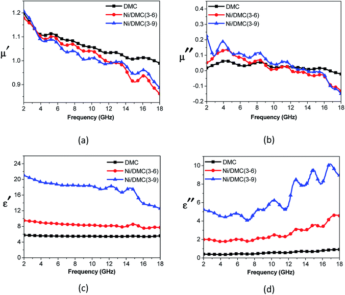 | ||
| Fig. 6 Relative permeability (a and b) and permittivity (c and d) of DMC and Ni/DMC composites versus frequency. | ||
However, the effect of Ni on the permittivity tells a contrasting story. As shown in Fig. 6(c) and (d), it can be observed that ε′ of DMC is almost constant at 2–18 GHz with a value near 6.0, while the imaginary part increases slowly from about 0.4 to 0.94. Introduction of Ni nanoparticle into the DMC has led to distinct improvement where ε′ is higher than 9.6 and ε′′ lies between 2.0 and 4.6. With increase of the Ni content, the permittivity could be further improved to over 20 with apparent dispersion at about 14 GHz, indicating a higher capability of EM dissipation. In view of the above results, it can be concluded that the influence of Ni nanoparticle has played a more pronounced role on the dielectric properties rather than the magnetic loss ability. Different from the magnetic property that is compositionally influenced, the dielectric properties could be affected by several factors. (i) As one of the most excellent conductor, addition of nickel strongly enhanced the conductivity and polarizability of DMC.18 This can be qualitatively understood according to the effective medium approximation.28 (ii) With the tremendous interface generated, introduction of Ni particles in nanoscale may bring on extra interfacial polarization arise from charge transfer between the two discontinuous dielectrics.25
3.3 Microwave absorption properties
When the EM wave is incident on the absorber, part of energy is reflected on the surface and another part is guided into the materials which may be attenuated gradually via dielectric loss and magnetic loss with the left directly passes through or reflected back when hitting the EM shielding materials. Therefore, according to the transmission line theory, the EM absorption properties is closely related to the reflection factor (Γ) and usually characterized with reflection loss (RL) according to eqn (2):29,30
RL = 20![[thin space (1/6-em)]](https://www.rsc.org/images/entities/char_2009.gif) lg|Γ| = 20 lg|Γ| = 20![[thin space (1/6-em)]](https://www.rsc.org/images/entities/char_2009.gif) lg|(Zin − Z0)/(Zin + Z0)| lg|(Zin − Z0)/(Zin + Z0)|
| (2) |
 | (3) |
In comparison with the ones of DMC, RL of Ni/DMC composites with the thickness of 2 mm and 3 mm were calculated according to the above equations and presented in Fig. 7. Taking the one of 2 mm for discussion, it is seen that the minimum reflection loss (RL) of DMC is −11.6 dB at 13 GHz and the absorption bandwidth (RL < −10 dB) is only about 1 GHz. For Ni/DMC (3–6), the EM absorption was effectively improved with a minimum RL of −23 dB at 8.8 GHz and the absorption bandwidth was broadened to be 4.5 GHz. As to the result for Ni/DMC (3–9) when more Ni nanoparticle have been incorporated into the 3-dimensional carbon skeleton with mesoporous structure, one can see that the performance could be even better as RL was further reduced to −27 dB. Correspondingly, the same trend can be also found for the thicker samples as shown in Fig. 7(b), except a shift of loss peak to lower band.
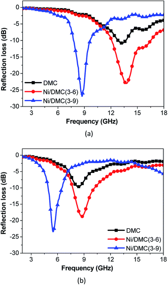 | ||
| Fig. 7 Comparison of reflection loss for DMC and Ni/DMC composites, (a) is the result for 2 mm samples, (b) is the result for 3 mm samples. | ||
Although the magnetic loss ability for Ni/DMC composites is still limited, the better absorption performance of Ni/DMC than pure DMC obviously indicates the importance of dielectric/magnetic incorporation for EM absorber. The synergetic interaction between the magnetic and non-magnetic component would probably have played an influential role and account for the final improvement of the EM absorption performance. As suggest by the BET specific area measuring results (Table 1), there is tremendous interface between the two discontinuous dielectrics where mobile charges accumulate according to the Maxwell–Wagner theory and polarize under the alternating external field.31 Consequently, the resulted interfacial polarization will contribute to the improvement of the EM wave dissipation efficiency as widely acknowledged.32
Furthermore, regarding to the specially designed structure of Ni/DMC in present work, it is also anticipated to make a difference on the EM wave multi-reflection. To verify the influence of the loosely core–shell structure on the final absorber performance, comparison of Ni/DMC composites with simple mixtures were further conducted, which were prepared by mechanically blending the as prepared DMC with commercial Ni nanoparticles and denoted as M (3–6) and M (3–9), respectively. As shown in Fig. 8, it is seen that absorption for Ni/DMC mixtures occurred at a relatively higher band. In addition, although the minimum RL of −15 dB is smaller than the one of neat DMC, the absorption efficiency of Ni/DMC mixtures are obviously inferior to Ni/DMC composites of which the minimized RL could be as low as −27 dB. According to the above results, it can be concluded that the structure of Ni/DMC also play a vital role in determining the final EM wave attenuation performance.
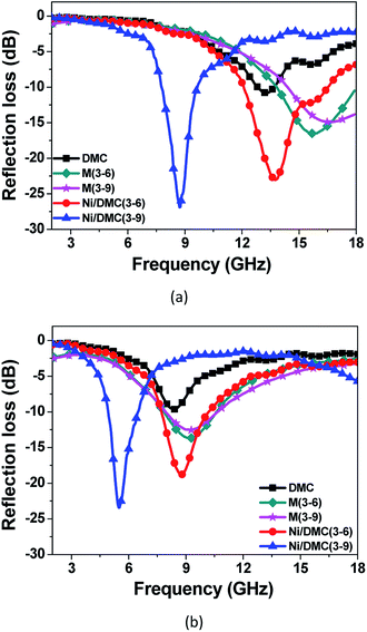 | ||
| Fig. 8 Comparison of reflection loss for Ni/DMC composites and Ni/DMC mixtures through mechanical blending, (a) is the result for 2 mm samples, (b) is the result for 3 mm samples. | ||
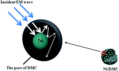
Generally, when the incident EM wave interacts with the absorber, a part of the energy is reflected on the surface of the absorber while the other part is attenuated inside the absorber. Benefits of EM absorption by a highly porous structure could be accounted from below aspects. (i) By tailoring the electromagnetic parameters through construction of a highly porous structure, propagation of EM wave into the absorber could be seriously increased owing to a better impedance matching. (ii) For the propagating EM wave in the absorber, enabled by the entrapment of EM wave in the highly porous absorber, the attenuation efficiency will be obviously improved through the so-called multiple reflection.25 For the circumstance of Ni/DMC composites in present work, different from the simple mixture of which the magnetic particles may be isolated, the loosely core–shell structure can be well maintained that the magnetic Ni particle exists as a core sheathed by the mesoporous carbon as schematically depicted in Fig. 9. It is presumed to act as a scattering centre that make the multiple reflection within the DMC pores even more effective. Therefore, the Ni/DMC composites of unique structure could be one of the most promising candidates for new generation of EM absorption materials with light weight and high EM wave absorption performance.
4. Conclusions
In summary, Ni/DMC composites have been successful prepared by a facile and effective two-step method, which can be analogously extended to preparation of other similar nano-metal decorated composites based on DMC. The Ni nanoparticles were in situ generated in the pores of mesoporous carbons, forming the unique loosely core–shell structure. Besides a better impedance matching by improving the magnetic properties, the dielectric loss ability of DMC was also strongly enhanced by the extra interfacial polarization. Moreover, the interaction between the EM wave and absorber can be effectively intensified with Ni nanoparticle being in the pours as a scattering centre. At the thickness of 2.0 mm, minimum RL value of DMC was reduced from −11.6 dB at 13 GHz to −27 dB at 9 GHz while the effective bandwidth was broadened from about 1 GHz to over 4.5 GHz, which can be tuned by properly adjusting the pore size and Ni content. Our results demonstrate that the porous Ni/DMC composites prepared in this work are attractive lightweight candidates for new generation of EM wave absorption materials.Acknowledgements
Y. C. is grateful for the Sustentation Fund by Introduced Post-doctoral Program of Guangdong Province of China. H. Z. is grateful for the support by the link project of the National Natural Science Foundation of China and Guangdong Province (No. U1401246), the National Natural Science Foundation of China (Grant No. 51276044), the Science and Technology Program of Guangdong Province of China (Grant No. 2016A020221031, 2015B010135011, 2015A050502047, 2014A010105047) and the Science and Technology Program of Guangzhou City of China (Grant No. 201508030018, 2016201604030040).References
- A. K. Dhami, Environ. Monit. Assess., 2012, 184, 6507–6512 CrossRef CAS PubMed.
- J. C. Wang, H. Zhou, J. D. Zhuang and Q. Liu, Phys. Chem. Chem. Phys., 2015, 17, 3802–3812 RSC.
- R. S. Meena, S. Bhattachrya and R. Chatterjee, Mater. Des., 2010, 31, 3220–3226 CrossRef CAS.
- J. Cao, W. Fu, H. Yang, Q. Yu, Y. Zhang, S. Wang, H. Zhao, Y. Sui, X. Zhou, W. Zhao, Y. Leng, H. Chen and X. Qi, Mater. Sci. Eng., B, 2010, 175, 56–59 CrossRef CAS.
- D.-L. Zhao, F. Luo and W.-C. Zhou, J. Alloys Compd., 2010, 490, 190–194 CrossRef CAS.
- X.-J. Zhang, G.-S. Wang, W.-Q. Cao, Y.-Z. Wei, M.-S. Cao and L. Guo, RSC Adv., 2014, 4, 19594–19601 RSC.
- D. Giasafaki, G. Charalambopoulou, A. Bourlinos, A. Stubos, D. Gournis and T. Steriotis, Adsorption, 2013, 19, 803–811 CrossRef CAS.
- P. Li, Y. Song, Z. Tang, G. Yang, Q. Guo, L. Liu and J. Yang, Ceram. Int., 2013, 39, 7773–7778 CrossRef CAS.
- Á. Sánchez-Sánchez, T. A. Centeno, F. Suárez-García, A. Martínez-Alonso and J. M. D. Tascón, Microporous Mesoporous Mater., 2016, 235, 1–8 CrossRef.
- M. Chen, L.-L. Shao, Y.-P. Liu, T.-Z. Ren and Z.-Y. Yuan, J. Power Sources, 2015, 283, 305–313 CrossRef CAS.
- S. Jia, Y. Wang, G. Xin, S. Zhou, P. Tian and J. Zang, Electrochim. Acta, 2016, 196, 527–534 CrossRef CAS.
- H. Xu, X. Yin, M. Zhu, M. Han, Z. Hou, X. Li, L. Zhang and L. Cheng, ACS Appl. Mater. Interfaces, 2017, 9, 6332–6341 CAS.
- X. Jia, J. Wang, X. Zhu, T. Wang, F. Yang, W. Dong, G. Wang, H. Yang and F. Wei, J. Alloys Compd., 2017, 697, 138–146 CrossRef CAS.
- T. C. Zou, N. Q. Zhao, C. S. Shi and J. J. Li, Bull. Mater. Sci., 2011, 34, 75–79 CrossRef CAS.
- X. Yuan, L. Cheng, S. Guo and L. Zhang, Ceram. Int., 2017, 43, 282–288 CrossRef CAS.
- L. Wang, H. Wu, Z. Shen, S. Guo and Y. Wang, Mater. Sci. Eng., B, 2012, 177, 1649–1654 CrossRef CAS.
- T. Wang, J. He, J. Zhou, J. Tang, Y. Guo, X. Ding, S. Wu and J. Zhao, J. Solid State Chem., 2010, 183, 2797–2804 CrossRef CAS.
- G. Li, L. Wang, W. Li and Y. Xu, Microporous Mesoporous Mater., 2015, 211, 97–104 CrossRef CAS.
- Y. Du, W. Liu, R. Qiang, Y. Wang, X. Han, J. Ma and P. Xu, ACS Appl. Mater. Interfaces, 2014, 6, 12997–13006 CAS.
- G.-M. Li, L.-C. Wang and Y. Xu, Chin. Phys. B, 2014, 23, 088105 CrossRef.
- H. J. Wu, L. D. Wang, Y. M. Wang, S. L. Guo and H. Wu, Mater. Res. Innovations, 2013, 18, 273–279 CrossRef.
- H. Zhu, H. Zhang, Y. Chen, Z. Li, D. Zhang, G. Zeng, Y. Huang, W. Wang, Q. Wu and C. Zhi, J. Mater. Sci., 2016, 51, 9723–9731 CrossRef CAS.
- H. Wang, X. Shi, W. Zhang and S. Yao, J. Alloys Compd., 2017, 711, 643–651 CrossRef CAS.
- K. Inomata and Y. Otake, Microporous Mesoporous Mater., 2011, 143, 60–65 CrossRef CAS.
- J. Fang, T. Liu, Z. Chen, Y. Wang, W. Wei, X. Yue and Z. Jiang, Nanoscale, 2016, 8, 8899–8909 RSC.
- X. Zhang, G. Ji, W. Liu, B. Quan, X. Liang, C. Shang, Y. Cheng and Y. Du, Nanoscale, 2015, 7, 12932–12942 RSC.
- X. Zhao, Z. Zhang, L. Wang, K. Xi, Q. Cao, D. Wang, Y. Yang and Y. Du, Sci. Rep., 2013, 3, 3421 CrossRef PubMed.
- K. P. Murali, S. Rajesh, O. Prakash, A. R. Kulkarni and R. Ratheesh, Composites, Part A, 2009, 40, 1179–1185 CrossRef.
- Y. Egami, T. Yamamoto, K. Suzuki, T. Yasuhara, E. Higuchi and H. Inoue, J. Mater. Sci., 2011, 47, 382–390 CrossRef.
- Y. Chen, Z. Lei, H. Wu, C. Zhu, P. Gao, Q. Ouyang, L.-H. Qi and W. Qin, Mater. Res. Bull., 2013, 48, 3362–3366 CrossRef CAS.
- Y. Chen and J. Wu, IEEE Trans. Dielectr. Electr. Insul., 2016, 23, 927–934 CrossRef CAS.
- J. Guo, X. Wang, P. Miao, X. Liao, W. Zhang and B. Shi, J. Mater. Chem., 2012, 22, 11933–11942 RSC.
| This journal is © The Royal Society of Chemistry 2017 |


