DOI:
10.1039/C7RA06923E
(Paper)
RSC Adv., 2017,
7, 51879-51887
Smart anti-corrosion self-healing zinc metal-based molybdate functionalized-mesoporous-silica (MCM-41) nanocomposite coatings†
Received
21st June 2017
, Accepted 24th September 2017
First published on 8th November 2017
Abstract
We report on the electrodeposition of smart corrosion-resistant zinc-based composite coatings containing mesoporous silica (MCM-41), impregnated with molybdate. The molybdate functionalization, which is known as a common corrosion inhibitor, was added as an “anti-corrosive self-healing” agent to the coating to be released during the corrosion process. The dispersion and bonding of the functional MCM-41 particles in the electrodeposition solution were both improved by adding 3-mercopropyltrimethoxysilane (MPTMS). Zinc metal base was co-deposited galvanostatically with the MCM-41 particles under conditions that were varied to achieve the smoothest and most corrosion-resistant films. The open circuit potential of Zn–MCM-41–SH–Mo (SH: silane, Mo: molybdate functionalization) in a chloride solution increases as a function of time owing to the release of Mo as an anodic inhibitor which makes the self-healing functionality in the coating. Based on electrochemical impedance spectroscopy and potentiodynamic polarization tests, it was observed that the corrosion resistance increases in the order: Zn–MCM-41–SH–Mo > Zn–MCM-41–Mo > Zn–MCM-41 > Zn.
1 Introduction
Composite coatings consisting of organic, inorganic, or hybrid functional materials have found enormous applications in engineering.1 The anti-corrosion smart coatings are functional and are increasingly being developed to improve corrosion protection.2
Capabilities like being independent and self-healing have made smart coatings distinctive. The healable polymer composites increase the functional lifetime of the resulting structures and coatings. In a self-healing mechanism (e.g. a zipper-like one), a reaction occurs between isocyanate groups and water particles in the air when the coating is damaged. According to the self-healing mechanisms, the polymer composites are classified into two main classes: (i) the intrinsic self-healing that occurs in the case of polymers heals cracks, and (ii) the extrinsic self-healing that takes place when the healing agent is pre-embedded. As to the former, the cracks are healed under specific situations in two ways: (1) physical interactions, whose healing process has been summarized through five steps: (a) surface rearrangement, (b) surface approach, (c) wetting, (d) diffusion, and (e) randomization, as well as (2) chemical interactions. The structural alterations in atoms or molecules may be the reason for cracks and deterioration so that the repairing strategies will be reverse reactions.3–7 Thin films are located in extrinsic self-healing coatings. In this group, crack rupture propagation causes the healing agent embedded in the matrix resin to be released from the encapsulation by capillary motion into crack planes, leading to their healing and to long-term durability. Until recent years, chromium compounds were known as the major self-healing anti-corrosion coatings. The self-healing mechanism involves the creation of a preserved oxide film in the damaged area. More recently, macromolecular compounds, such as silica, cerium, and sodium tetraoxomolybdate, have been proved to produce self-healing, anti-corrosion organic paint coatings.5–8
Electro-galvanized (or electrodeposited zinc) coatings are one of the most important metallic coatings in many industries due to their sacrificial cathodic protection and low costs. Previous studies on composite coatings involve Zn–TiO2,9 Zn–Al2O3,10 Zn–yttria-stabilized zirconia,11 Zn–Ni–SiO2,12 Zn–SiO2,13–21 Zn–mica,13 and Zn-hybrid nanoparticles.22 Very recently, by incorporating silica particles into zinc, the concept of “self-healing” coatings15 has been recommended for the corrosion inhibition of steel sheets at the cut edge, like other well-developed organic and inorganic self-healing coatings.15,23–29 At high pH, the silica particles will be decomposed and release the accumulated inhibitor. The co-deposition of SiO2 and MPTMS-CPTMS (225 nm in diameter) has been reported.30,31 By making SiO2 particles more hydrophobic, the interface energy between the particles and the zinc matrix will increase; therefore, a driving force will be provided for the incorporation of SiO2 into the zinc matrix. The distribution is thoroughly inhomogeneous in the zinc coating; similarly, the SiO2 particles are not agglomerated.30,31 In addition, super-hydrophobic porous coatings containing silane also have a self-healing ability. For particles with a diameter larger than a crucial amount, incorporation might take place.30–32
The application of self-healing paint coatings has also received much attention. For example, a polymer based-composite paint with mesoporous silica has been prepared and it has been shown that by releasing the small molecules stored in the nanoporous surfaces, self-healing surfaces are also created. For instance, molybdate can be added to the particle surface, which alternatively migrates to the surface and performs the self-repairing.33 Wang et al.34 reported that the addition of 0.05 M MoO42− to a 01 M H2SO4 solution leads to a corrosion-inhibition efficiency of 71% owing to the formation of a Mo-rich protective layer.
For the first time, we used mesoporous silica MCM-41 as a reservoir of molybdate (Na2MoO4) as well as a silane surface functionalizing agent as the self-healing anti-corrosion functional material in electro-galvanized coatings. The molybdate ion as a corrosion inhibitor was added to MCM-41 by impregnation. This paper aims to study the electrochemical behavior of Zn–MCM-41, Zn–MCM-41–Mo, and Zn–MCM-41–SH–Mo electrodeposition on steel in 0.5% NaCl by analyzing the effect of adding Na2MoO4·2H2O and Mo to MCM-41 through impregnation. It is known that oxy-anions like chromate, such as molybdate, have an effective inhibiting ability. When the coating was immersed in a corrosive medium, it was anticipated that corrosion inhibitors would begin to be released and that the corrosion process rate would decline.
2 Experimental
2.1. Materials
Mesoporous silica (MCM-41) with a diameter of 225–425 nm –ZnSO4·7H2O (Sigma-Aldrich), hexadecyltrimethyl-ammonium bromide CTAB (98% Aldrich), tetraethoxysilane (TEOS, Fluka), ammonia solution (50% Merck), ethanol (absolute reagent type, Merck), 3-mercopropyltrimethoxysilane (MPTMS, Aldrich), Na2MoO4·2H2O with a diameter of 0.25 nm Merck, and deionized water were purchased.
2.2. The synthesis of mesoporous silica
Mesoporous silica with a hexagonal structure, uniform cylindrical 2–50 nm diameter pores, high specific surface area, and high chemical and thermal ability, was synthesized. The preparation of a spherical MCM-41 molecular sieve was performed at room temperature in a typical synthesis process;35 0.7 g of CTAB was added to 134.5 mL of deionized H2O under stirring. After the solution was solvated, 47.5 mL of ethanol and 14 mL of ammonia were added to the solution and were mixed for 5 min; then 2.8 mL of TEOS was added under stirring. The stirring was continued for 3 h at 45 °C. By centrifugation at 5000 rpm, the SiO2 particles were separated from the solution and dried at room temperature overnight. Finally, the particles were calcined at 560 °C for 6 h with a heating rate of 1 °C min−1.
2.3. The impregnation of mesoporous silica and molybdate
The MCM-41 spherical particles were impregnated with molybdate (Na2MoO4·2H2O with a diameter of 0.25 nm, Merck).36 The molybdate content was ca. 10% of MCM-41 because the structure of MCM-41–Mo changed from hexagonal to amorphous by increasing the molybdenum content. 0.2 g of sodium molybdate powders were mixed with 2 g of MCM-41 in 200 mL of water under stirring (at a rate of 1200 rpm). The stirring was continued for 24 h at 45 °C, followed by drying at 100 °C in an oven for 12 h. The mixtures were then calcined at 550 °C for 8 h with a heating rate of 1 °C min−1.
2.4. The modification of mesoporous silica
The modification of MCM-41–Mo particles took place in accordance with standard procedures.36 2 mL of MPTMS(3-mercaptopropyltrimethoxysilane) was added to a solution including 100 mg of MCM-41 dispersed in ethanol. By centrifugation at 5000 rpm of the MCM-41, the modified particles were separated from the solution, dried at room temperature overnight, and further dried for 5 hours at 70 °C in a vacuum-oven.
2.5. The zinc–MCM-41–Mo electrodeposition
The electrodeposition was galvanostatically performed in a two-electrode cell with graphite as the anode, and low carbon steel grade St-37 as the cathode. First, the substrates were ground with 5000-grade SiC grinding paper; afterward they were cleaned with ethanol and water in a ultrasonic bath for 10 min. The electrodeposition electrolyte consisted of 10 mL of 1.2 M ZnSO4 and 100 mg of mesoporous silica (MCM-41) and modified mesoporous silica particles for the electrodeposition of MCM-41–Mo and MCM-41–Mo–SH coatings. The electrodeposition current density employed was 17.5 A cm−2 at pH = 3. In a second method, 4 × 10⁻² M of molybdate was added to the same electrolyte containing 10 mL of 1.2 M ZnSO4 in order to electrodeposit Zn–MCM-41–Mo without functionalization coatings. The bath was also rigorously agitated with a magnetic stirrer at a rate of 1200 rpm. We employ specific notation for different metal-based composite coatings throughout the paper. For further assistance, a list of all the coatings is summarized in Table 1. Table 2 also shows the electrodeposition parameters employed.
Table 1 Description of notation used for particle specifications and zinc-based coatings electrodeposited with different silica particles
| Sample |
Name |
Materials |
| 1 |
Zn |
Zinc |
| 2 |
Zn–MCM-41 |
Zinc + mesoporous silica MCM-41 |
| 3 |
Zn–MCM-41–Mo |
Zinc + mesoporous silica MCM-41 functionalized by impregnating with molybdate before electrodeposition |
| 4 |
Zn–MCM-41–Mo without functionalization |
Zinc + mesoporous silica MCM-41 + molybdate added in electrodeposition solution |
| 5 |
Zn–MCM-41–Mo–SH |
Zinc + mesoporous silica MCM-41 41 functionalized with molybdate and surface modified with silane |
Table 2 The composition of Zn–MCM-41 and Zn–MCM-41–Mo composite coatings electrodeposited at a current density of Id = 17.5 A cm−2
| Coating |
wt% of MCM-41 |
wt% of Zn |
wt% of Mo |
wt% O |
| Zn–MCM-41 |
5.21 |
76.22 |
— |
18.57 |
| Zn–MCM-41–Mo functionalized |
4.8 |
68.2 |
4 |
23 |
| Zn–MCM-41–Mo without functionalization |
1.3 |
64.42 |
1.00 |
31.38 |
| Zn–MCM-41–Mo–SH |
4.03 |
77.81 |
3.8 |
14.36 |
2.6. Materials characterization
A Fourier transform infrared spectroscopy (FT-IR) test was performed with a scan range of 2.5–15 μm with a high-resolution scanning electron microscope (FESEM Hitachi) furnished with energy dispersive X-ray spectroscopy (EDS-Oxford equipment), and the morphology of the MCM 41–Mo and MCM-41, the coatings and the SiO2 content quality in the deposition were examined. X-ray diffraction (XRD-Bruker equipped with Philips X'Pert software) was employed running at 40 kV and 30 mA by Cu Kα radiation over a scan range of 20 < 2θ < 100° with a step size of 0.02°. The corrosion properties of Zn–MCM-41, Zn–MCM-41–Mo, and Zn–MCM-41–SH–Mo in 0.5% NaCl (pH = 4.6) were determined. A calomel electrode, a platinum plate, and Zn–MCM-41, Zn–MCM-41–Mo, or Zn–MCM-41–SH–Mo with an area of 1 cm2 were taken as the reference electrode, counter, and working electrode, respectively. The corrosion behavior of the electrodeposited coatings was evaluated by different techniques, including open circuit potential–time curves, electrochemical impedance spectroscopy (EIS) and potentiodunamic polarization methods. All the electrochemical examinations were carried out in a conventional three electrode cell consisting of the coating materials as the working electrode, a Pt foil as the counter electrode and an Ag/AgCl reference electrode in an electrolyte of 1.5 M NaCl solution. Depending on the test, we employed a potentiostat/galvanostat model Autolab-PGSTAT 30 as well as a potentiostat/galvanostat with impedance module Zahner model IM-6. EIS tests were performed at a potential amplitude of 5 mV in a frequency range between 100 KHz and 10 mHz. Polarisation curves were recorded at a potential sweep rate of 1 mV s−1. The electrochemical calculations were carried out with the assistance of Electrochemistry Power Suite software. The corrosion current density (Icorr) and polarization resistance (Rp) were calculated using the Stern–Geary method.37 The corrosion rate was also calculated using Faraday's law. The data obtained by polarization curves were analyzed by the Soft-core-III power suite program. EIS data were analyzed by Z-View 2.8 software to model the equivalent electrical circuits.
3 Results and discussions
3.1. Surface functionalization of mesoporous silica (MCM-41) with molybdate
Fig. 1a illustrates a typical FESEM image of mesoporous silica MCM-41 particles functionalized by molybdate. As is evident in the figure, the MCM-41–Mo particles have a spherical mesoporous structure and morphology. Fig. 1b shows the size distribution histograms measured on the SEM image. Two size ranges are encountered: (i) MCM-41–Mo particle size and (ii) mesoporous size. On the one hand, as the upper panel in Fig. 1b illustrates, the size distribution shows meso-porosity in a range of less than 50 nm with an average pore diameter of less than 5 nm. This is the main characteristic of our methodology for obtaining a smart anti-corrosion function in a zinc metal based composite coating. On the other hand, as shown in the lower panel of Fig. 1b, the size distribution histogram determines the overall size of the MCM-41 silica particles to have a diameter ranging from 225 to 425 nm. The average diameter size of the particles is about 265 nm.
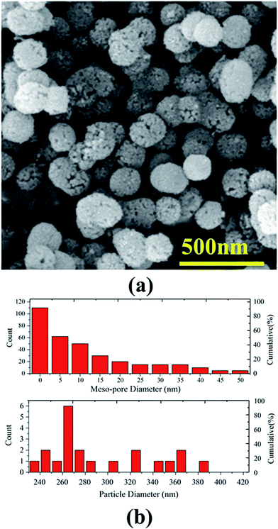 |
| | Fig. 1 (a) A typical SEM micrograph of synthesized mesoporous silica (MCM-41) particles functionalized by Mo, (b) corresponding meso-pore size (upper panel) and particle size (lower panel) distribution histograms. | |
Fig. 2 shows the FT-IR spectrum of MCM-41–Mo. The absorption peaks at 472.5 and 1110.41 cm−1 are associated with the Si–O stretching frequency in SiO2, whose peaks at 472.5 and 1110.41 correspond to δ bond O–Si–O and ν bond Si–O–Si, respectively. Moreover, 3278.29 cm−1 is attributed to Si–OH bonds. In addition, the absorption peaks at 900.77 cm−1 are attributed to the Mo![[double bond, length as m-dash]](https://www.rsc.org/images/entities/char_e001.gif) O stretching frequency of MoO42. The absorption peaks at both 858.05 and 831.31 cm−1 are attributed to the Mo–O–Mo stretching frequency.38
O stretching frequency of MoO42. The absorption peaks at both 858.05 and 831.31 cm−1 are attributed to the Mo–O–Mo stretching frequency.38
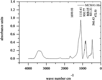 |
| | Fig. 2 FTIR curve of the molybdate functionalized mesoporous silica (MCM-41–Mo). | |
3.2. The co-electrodeposition and morphological characterization of Zn-matrix functionalized MCM-41 particles
We have studied the co-electrodeposition of zinc-based MCM-41 functionalized by molybdate and molybdate-silane composite coatings. We find that the Zn–MCM-41 electrodeposited coating exhibits homogenous dispersion and pertinent adhesion to the zinc metal matrix. The SEM image taken from the cross section of MCM-41–SH–Mo shown in Fig. 3 illustrates that there was neither agglomeration nor defects. However, it is probable that some preferential pathways were created as a result of functionalization of molybdate with MCM-41–SH.39 This might be due to an increase in their incorporation into the coating by functionalizing MCM-41 with –SH, which improves the incorporation of particles into the metal matrix.31,40–42
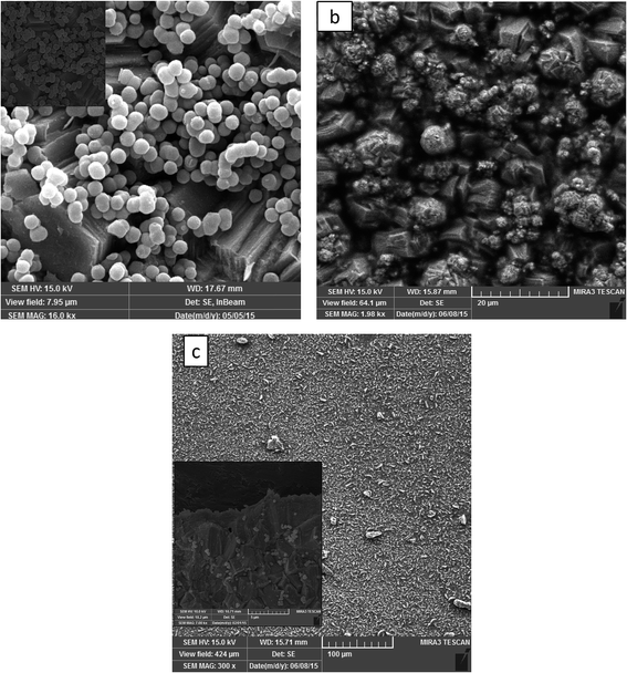 |
| | Fig. 3 SEM images of (a) Zn–MCM-41, (b) Zn–MCM-41–Mo functionalized and (c) Zn–MCM-41–Mo–SH composite coatings electrodeposited at Id = 17.5 A cm−2 with a particle load of 1 g L−1. | |
3.3. The crystalline structure of the Zn-matrix functionalized MCM-41 particles
The XRD patterns of the Zn–MCM-41, Zn–MCM41–Mo and Zn–MCM-41–SH–Mo electrodeposited coating have been illustrated in Fig. 4. Crystallite size and internal microstrain were determined based on the Williamson–Hall (W–H) method, as shown in Table 3.
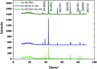 |
| | Fig. 4 The XRD patterns of Zn–MCM-41, Zn–MCM-41–Mo and Zn–MCM-41–Mo–SH. | |
Table 3 The crystalline structure data calculated on XRD data by the Williamson–Hall method
| Deposition condition |
Crystallite size (nm) |
Internal microstrain |
| Zn–MCM-41 |
Id = 17.5 A cm−2 |
25.25 |
0.0567 |
| Zn–MCM41–Mo functionalized |
Id = 17.5 A cm−2 |
30.12 |
0.0855 |
| Zn–MCM-41–Mo–SH |
Id = 17.5 A cm−2 |
15.015 |
0.0647 |
This indicates that the crystallite grain size will be increased after the coating has been modified by molybdate. This can be ascribed to the following factor: MCM41–Mo in the coating is like a barrier layer for the crystal growth and contributes to the decline in the nucleation rate. Furthermore, the crystallite size for MCM-41–Mo–SH decreases as the nucleation rate and nucleation preferential places increase. The inconsistency between the strengthening phase and the zinc matrix indicates the internal microstrain. By the modification of MCM-41–Mo with SH the internal microstrain will be reduced since the lattice mismatch declines; therefore, the particle distribution will increase.
3.4. The corrosion behavior of the Zn–MCM-41–Mo coatings in 1.5 M NaCl
There are several reports about the corrosion properties of the electrodeposited zinc matrix composite containing silica, as well as some reports that have studied the corrosion properties of silica mesoporous–Mo as a corrosion inhibitor in paint coatings.39,43 In the present work, we have developed metal-matrix composite coating containing functionalized MCM-41 with molybdate as the anti-corrosion self-healing agent and studied their corrosion properties. In addition, the comparison between the corrosion properties of Zn–MCM-41, Zn–MCM-41–Mo, and Zn–MCM-41–SH–Mo was made to confirm the self-healing property of the coatings with the addition of Mo.
3.4.1. The open circuit curves (OCP). Fig. 5a shows the variation of open circuit potential (OCP) of the composite coatings as a function of time recorded in the 1.5 M NaCl solution for a short period of time. It shows that the presence of inhibiting functionalization by molybdate impose a positive effect on the zinc coating protection. By adding silica mesoporous, the functionalized molybdate corrosion potential shifts to the positive values in the sequence of Zn–MCM-41–SH–Mo > Zn–MCM-41–Mo functionalized > Zn–MCM-41–Mo > Zn–MCM-41. This is even more pronounced in Fig. 5b, where it demonstrates the OCP plot recorded in the same solution for longer period of time 30 days. Potential of Zn–MCM-41–Mo coating changes towards more positive potentials as a function of time. This is due to anodic protection of molybdate this is caused by anodic dissolution and cathodic protection of steel base metal. The amount of anodic polarization means that zinc dissolve off from the coating and that the corrosion occurs. However, the potential changes of OCP of Zn–MCM-41 are also positive but are smaller indeed. On the mechanism of molybdate inhibiting action, it has been reported that Mo(VI) is a weak oxidizing agent. This acts here as an anodic inhibitor during the process of formation MCM-41–Mo protective layer.44,45 The process of passivation of Fe could be controlled by the molybdate active agent.46,47 Also by functionalization by –SH the amount of anodic polarization decreases, which is due to the formation of stronger barrier layer on the surface.39,48
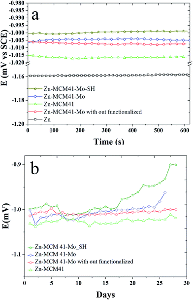 |
| | Fig. 5 The variation in open circuit potential (OCP) as a function of time recorded in 1.5 M NaCl solution at pH = 4.6 for: (a) Zn–MCM-41, Zn–MCM-41–Mo functionalized, Zn–MCM-41–Mo, Zn–MCM-41–Mo–SH electrodeposited coatings recorded for 600 min; (b) Zn–MCM-41, Zn–MCM-41–Mo functionalized, Zn–MCM-41–Mo, Zn–MCM-41–Mo–SH electrodeposited coatings recorded for 30 days. | |
3.4.2. Electrochemical impedance spectroscopy (EIS). Fig. 7 shows the Nyquist and Bode plots measured for different Zn–MCM-41 functionalized nanocomposite coatings electrodeposited under different conditions in the 1.5 M NaCl solution at room temperature. Three kinds of equivalent circuits were applied, as shown in Fig. 6, composed of the elements which correspond to the solution resistance (Rs), double-layer constant phase (CPE2), charge transfer resistance (R2), film constant phase (CPE1), and film resistance (R1). Due to a non-ideal capacitive reply, the CPE interface was used instead of the pure capacitance. The impedance of CPE was determined by [Q(jω)n]−1, where Q is the constant of the interfacial capacitance, and j, ω and n represent the imaginary number, angular frequency, and exponential factor in the range between 0 and 1, respectively. The behavior of pure capacitance is recognized by n − 1, and the acceptable ranges of n are from 0 to 1. W is the Warburg impedance, which hints at the ion transport or diffusion of electro-active particles along the electrode surface; also L is an inductor. The optimized values of the equivalent circuit elements are subsequently determined to fit the data by using ZVIEW software. The coatings have been summarized in Table 4 for Zn–MCM-41, Zn–MCM-41–Mo, and Zn–MCM-41–SH–Mo. The equivalent circuits fitted by ZVIEW completely exhibited the low error (X2) value of almost 30 data points. Previously, it had been proved that MoO42− and CrO42− ions lead to a rise in corrosion potential.39 The charge transfer resistance (Rc) value for Zn–MCM-41 is 286 Ω cm2. Moreover, the charge transfer resistance of Zn–MCM-41–Mo is higher than that of Zn–MCM-41. As the molybdate ion is released into the matrix and protective compounds, the following electrochemical reactions are formed on the surface and the corrosion rate is reduced.39,43,48
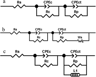 |
| | Fig. 6 The equivalent circuit models used for fitting the experimental results of the Zn–MCM-41, Zn–MCM-41–Mo and Zn–MCM-41–Mo–SH electrodeposited coatings immersed in 1.5 M NaCl solution. | |
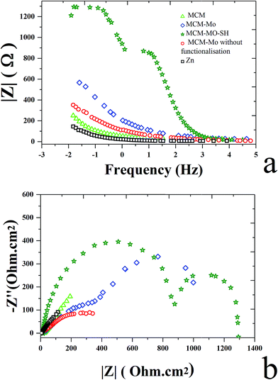 |
| | Fig. 7 (a) The Bode plot for electrodeposited Zn, Zn–MCM-41, Zn–MCM-41–Mo functionalized, Zn–MCM-41–Mo, Zn–MCM-41–Mo–SH electrodeposited coatings measured in 1.5 M NaCl solution. (b) The Nyquist plot for electrodeposits: Zn, Zn–MCM-41, Zn–MCM-41–Mo functionalized, Zn–MCM-41–Mo, Zn–MCM-41–Mo–SH electrodeposited coatings measured in 1.5 M NaCl solution. | |
Table 4 The electrochemical impedance spectroscopy parameters calculated according to their equivalent electrical circuit for electrodeposited coatings in 0.5 wt% NaCl solution
| Deposition condition |
Zn |
Zn–MCM-41–Mo functionalized |
Zn–MCM-41–Mo |
Zn–MCM-41 |
Zn–MCM-41–Mo–SH |
| Current density |
Id = 17.5 mA dm−2 |
Id = 17.5 mA dm−2 |
Id = 17.5 mA dm−2 |
Id = 17.5 mA dm−2 |
Id = 17.5 mA dm−2 |
| Rs (Ω cm2) |
6.165 |
21.47 |
2.884 |
24.11 |
18.25 |
| CPE1-T (F cm−2 sp−1) |
0.025298 |
0.0019869 |
0.0053204 |
0.01405 |
4.6125 × 10⁻⁵ |
| CPE1-P (F cm−2 sp−1) |
0.5974 |
0.38426 |
0.27974 |
0.41832 |
0.75373 |
| Rc (Ω cm2) |
468.6 |
193.6 |
22.36 |
70.03 |
543.1 |
| CPE2-T (F cm−2 sp−1) |
0.045661 |
0.0029528 |
0.0042605 |
0.024886 |
0.015887 |
| CPE2-P (F cm−2 sp−1) |
0.63211 |
0.62938 |
0.42896 |
0.70122 |
0.65931 |
| Rp (Ω cm2) |
8.994 |
917.8 |
500.7 |
900 |
2730 |
| W–R |
|
50 |
25.77 |
3001 |
— |
| W–T |
|
340 |
18.82 |
70.48 |
— |
| W–P |
|
0.428 |
0.48 |
68![[thin space (1/6-em)]](https://www.rsc.org/images/entities/char_2009.gif) 917 917 |
— |
| L |
|
|
|
|
−34.63 |
First of all, it is anticipated that (1) the process of zinc oxidation occurs; and simultaneously, (2) oxygen is dissolved in the aqueous medium and is reduced by producing OH− ions since (3) the process is the overall superior reaction; then (4) when the cathode potential achieves the equilibrium potential of Zn (−0.96 V vs. Ag/AgCl), the MCM-41 particles will be adsorbed on the cathode surface.
| |
 | (2) |
| | |
2Zn + O2 + 2H2O → 2Zn(OH)2
| (3) |
| | |
Zn(OH)2 + MCM41(SMP) + 2e− → Zn − MCM41(SMP) + 2OH−
| (4) |
Furthermore, over the zinc layer, where the pH value is low, the Zn2+ concentration is improved. Far from the zinc layer, the amount of Zn2+ is decreased. When corrosion occurs, Zn2+ is released. Hence, the dissolution by chloride and passivation by the oxygen reduction take place. Moreover, zinc is an anodic inhibitor.39
| 5Zn(aq)2+ + H2O(l) + 8OH(aq)− + 2Cl(aq)− → Zn5Cl2(OH)8·H2O(s) |
Some authors have mentioned some formation mechanisms that might be possible for molybdate presentation on the zinc surfaces of coatings. Wharton et al.49 have reported that by combining zinc cations and molybdate anions, zinc molybdenum oxide may form:
| | |
3[Mo7O24]6− + 14Zn2+ + 32H+ + 42e− → Zn2Mo3O8 + 16H2O
| (7) |
Rout et al.50 have reported that zinc molybdate may be formed by combining zinc cations and molybdate anions:
| | |
Na2MoO4 + 2H+ → H2MoO4 + 2H+
| (9) |
| | |
H2MoO4 + Zn2+ → ZnMoO4 + 2H+
| (10) |
| | |
Zn2+ + HMoO4− → ZnMoO4 + H+
| (11) |
Dutra et al.39 have reported that zinc cations combine with molybdate anions and form zinc oxide and MoO2 or MoO3:
| Zn + MoO42− + H2O → ZnO+ MoO2 + 2OH− |
Moreover, molybdate (MoO42−) has been utilized as a preservative for a soft water cooling system in the presence of an oxidizing agent because of its non-toxic property.51 Besides, the defects can also be repaired.52 Furthermore, there is another mechanism of corrosion inhabitation by molybdate ions when they react with chloride:
| MoO42− + 4H+ + 2Cl− → MoO2Cl2 + 2H2O |
The product of corrosion (MoO2Cl2) is insoluble, which will be deposited on the surface of the coatings and will control the diffusion of Cl− from NaCl. In addition, the passivation of metals will occur with a reduction of molybdate.48 Indeed, chloride ions lead to release of the molybdate ion due to the creation of negative zeta potential on the mesoporous silica.33
3.4.3. Potentiodynamic polarization curves. The results of the potentiodynamic polarization test of Zn, Zn–MCM-41, Zn–MCM-41–Mo, and Zn–MCM-41–SH–Mo in 1.5 M NaCl are shown in Fig. 8. The most important parameters were calculated from the polarization curves and are summarized in Table 5. It can be seen that all composite coatings exhibit more positive corrosion potentials compared to pure zinc electrodeposited coatings. However, the magnitude of the positive shift is different for different silica particles. The Zn–MCM-41–Mo functionalized electrodeposited coating has the most positive corrosion potential among all the different composite coatings. On the other hand, the cathodic and anodic branches of the polarization curves measured for Zn–MCM-41–SH–Mo, Zn–MCM-41–Mo, and Zn–MCM-41 shifted to more positive potentials and as a result, the rate of corrosion also decreases as a consequence of the addition of silica particles in different forms. It is evident from the data on corrosion current density and rates of different electrodeposited coatings defined by the Stern–Geary equation that: Zn–MCM-41–SH–Mo electrodeposited composite coating is the most corrosion resistive coating. This observation is also consistent with other results obtained by EIS data. Furthermore, the corrosion current density was reduced in the sequence Zn–MCM-41–SH–Mo > Zn–MCM-41–Mo > Zn–MCM-41, as shown in Table 4. It is obvious that in addition to improvement in corrosion potential, the corrosion rate likewise declines when the molybdate is added as a functionalizing agent, making the coating a smart anti-corrosion material. This indicates that molybdate was released from MCM-41–Mo and the insoluble corrosion products appearing on the surface of the coatings have the self-healing property. As can be seen, when silane is added to the MECM-41 particles, the corrosion resistance increases. In fact, by adding silane on the silica surface, the barrier layer becomes more resistant. As a result, corrosion resistance increases. These results confirmed the EIS and OCP results as well.47,51–55
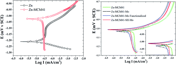 |
| | Fig. 8 Typical potentiodynamic polarization curves obtained for Zn, Zn–MCM-41, Zn–MCM-41–Mo, Zn–MCM-41–SH–Mo electrodeposited coatings (Id = 17.5 mA cm−2) measured in 1.5 M NaCl solution. | |
Table 5 Corrosion parameters calculated from the potentiodymanic polarization curves for different electrodeposited coatings in 1.5 M NaCl solution
| Deposition condition |
Ecorr (V) |
Icorr (A cm−2) |
Corrosion rate (mpy) |
βc (mV per decay) |
βa (mV per decay) |
Rp (Ω) |
| Zn |
Id = 17.5 A cm−2 |
−1.274 |
5.254 × 10⁻⁶ |
77 |
176.36 |
433.30 |
10.36 |
| Zn–MCM-41 |
Id = 17.5 A cm−2 |
−1.037 |
3.986 × 10⁻⁶ |
58.3 |
460.468 |
50.301 |
4.93 |
| Zn–MCM-41–Mo-functionalized |
Id = 17.5 A cm−2 |
−9.97 |
2.017 × 10⁻⁶ |
29.37 |
130.958 |
49.372 |
7.71 |
| Zn–MCM-41–Mo |
Id = 17.5 A cm−2 |
−1.018 |
2.018 × 10⁻⁶ |
29.49 |
425.036 |
43.646 |
8.52 |
| Zn–MCM-41–SH–Mo |
Id = 17.5 A cm−2 |
−1.001 |
1.269 × 10⁻⁶ |
18.9 |
56.926 |
18.786 |
4.8 |
4 Conclusion
The self-healing performance and mechanism of Zn–MCM-41–Mo were investigated by OCP, EIS, and polarization curves. Mesoporous silica particles impregnated with molybdate as a corrosion inhibitor were utilized to create a self-healing factor to reduce the rate of corrosion. The results illustrate that protective compounds are formed after release of molybdate from mesoporous silica, which contributes to an increase in the corrosion protection. Silane was added to form a stronger barrier layer; besides, silane MPTMS has a self-healing property via two mechanisms. Firstly, it reduced the porosity of the metal matrix coating which contributes to improved barrier performance. Secondly, silane SH improved the adherence of the coating by make it hydrophobic. The rate of corrosion is reduced in the sequence of Zn–MCM-41–SH–Mo > Zn–Mo functionalized-MCM-41 > Zn–MCM-41–Mo > Zn–MCM-41.
Conflicts of interest
We declare no conflict of interest.
References
- A. A. Aal, Mater. Sci. Eng., A, 2008, 474, 181–187 CrossRef.
- M. Montemor, Surf. Coat. Technol., 2014, 258, 17–37 CrossRef CAS.
- T. Siva and S. Sathiyanarayanan, Prog. Org. Coat., 2015, 82, 57–67 CrossRef CAS.
- A. Stankiewicz, I. Szczygieł and B. Szczygieł, J. Mater. Sci., 2013, 48, 8041–8051 CrossRef CAS.
- D. Y. Wu, S. Meure and D. Solomon, Prog. Polym. Sci., 2008, 33, 479–522 CrossRef CAS.
- Y. Yang and M. W. Urban, Polym. Lett., 2008, 238–250 Search PubMed.
- Y. Yuan, T. Yin, M. Rong and M. Zhang, Polym. Lett., 2008, 2, 238–250 CrossRef CAS.
- J. A. Syrett, C. R. Becer and D. M. Haddleton, Polym. Chem., 2010, 1, 978–987 RSC.
- K. Wessels, A. Feldhoff, M. Wark, J. Rathousky and T. Oekermann, Electrochem. Solid-State Lett., 2006, 9, C93–C96 CrossRef CAS.
- S. Price, V. Randle and M. Pichilingi, Ironmaking Steelmaking, 1999, 26, 378–386 CrossRef CAS.
- X. Xia, I. Zhitomirsky and J. R. McDermid, J. Mater. Process. Technol., 2009, 209, 2632–2640 CrossRef CAS.
- Y. Ullal and A. C. Hegde, Surface Engineering and Applied Electrochemistry, 2013, 49, 161–167 CrossRef.
- M. Azizi, W. Schneider and W. Plieth, J. Solid State Electrochem., 2005, 9, 429–437 CrossRef CAS.
- K. Kondo, A. Ohgishi and Z. Tanaka, J. Electrochem. Soc., 2000, 147, 2611–2613 CrossRef CAS.
- E. V. Skorb, D. Fix, D. V. Andreeva, H. Möhwald and D. G. Shchukin, Adv. Funct. Mater., 2009, 19, 2373–2379 CrossRef CAS.
- A. Simões, J. Torres, R. Picciochi and J. Fernandes, Electrochim. Acta, 2009, 54, 3857–3865 CrossRef.
- J. Cao, L. Li, J. Wu, Y. Lu and Z. Gui, Corrosion, 2002, 58, 698–702 CrossRef CAS.
- A. Gomes and M. da Silva Pereira, Electrochim. Acta, 2006, 52, 863–871 CrossRef CAS.
- A. L. Marshall, Trans. Faraday Soc., 1925, 21, 297–314 RSC.
- I. Wark, J. Appl. Electrochem., 1979, 9, 721–730 CrossRef CAS.
- T. J. Tuaweri and G. Wilcox, Surf. Coat. Technol., 2006, 200, 5921–5930 CrossRef CAS.
- O. Kammona, K. Kotti, C. Kiparissides, J.-P. Celis and J. Fransaer, Electrochim. Acta, 2009, 54, 2450–2457 CrossRef CAS.
- S. R. White, N. Sottos, P. Geubelle, J. Moore, M. R. Kessler, S. Sriram, E. Brown and S. Viswanathan, Nature, 2001, 409, 794–797 CrossRef CAS PubMed.
- G. Paliwoda-Porebska, M. Stratmann, M. Rohwerder, K. Potje-Kamloth, Y. Lu, A. Z. Pich and H.-J. Adler, Corros. Sci., 2005, 47, 3216–3233 CrossRef CAS.
- M. Rohwerder and A. Michalik, Electrochim. Acta, 2007, 53, 1300–1313 CrossRef CAS.
- M. Rohwerder and A. Michalik, Electrochim. Acta, 2009, 54, 6075–6081 CrossRef CAS.
- M. L. Zheludkevich, D.
G. Shchukin, K. A. Yasakau, H. Möhwald and M. G. Ferreira, Chem. Mater., 2007, 19, 402–411 CrossRef CAS.
- D. G. Shchukin and H. Möhwald, Small, 2007, 3, 926–943 CrossRef CAS PubMed.
- D. Borisova, H. Möhwald and D. G. Shchukin, ACS Nano, 2011, 5, 1939–1946 CrossRef CAS PubMed.
- T. R. Khan, A. Erbe, M. Auinger, F. Marlow and M. Rohwerder, Sci. Technol. Adv. Mater., 2011, 12, 055005 CrossRef PubMed.
- T. R. Khan, A. Vimalanandan, F. Marlow, A. Erbe and M. Rohwerder, ACS Appl. Mater. Interfaces, 2012, 4, 6221–6227 CAS.
- L.-K. Wu, J.-M. Hu and J.-Q. Zhang, Corros. Sci., 2012, 59, 348–351 CrossRef CAS.
- M. Yeganeh, M. Saremi and H. Rezaeyan, Prog. Org. Coat., 2014, 77, 1428–1435 CrossRef CAS.
- D. Wang, X. Tang, Y. Qiu, F. Gan and G. Z. Chen, Corros. Sci., 2005, 47, 2157–2172 CrossRef CAS.
- H. Meléndez-Ortiz, L. García-Cerda, Y. Olivares-Maldonado, G. Castruita, J. Mercado-Silva and Y. Perera-Mercado, Ceram. Int., 2012, 38, 6353–6358 CrossRef.
- D. H. Cho, T. S. Chang, S. K. Ryu and Y. K. Lee, Catal. Lett., 2000, 64, 227–232 CrossRef CAS.
- M. Stern and A. L. Geary, J. Electrochem. Soc., 1957, 104, 56–63 CrossRef CAS.
- A. Bayat, M. Shakourian-Fard and M. M. Hashemi, Catal. Commun., 2014, 52, 16–21 CrossRef CAS.
- C. A. Dutra, E. N. Codaro and R. Z. Nakazato, Mater. Sci. Appl., 2012, 3, 348 CAS.
- F. Nasirpouri, in Electrodeposition of Nanostructured Materials, Springer International Publishing, Switzerland, 2017 Search PubMed.
- B. Bakhit, A. Akbari, F. Nasirpouri and M. G. Hosseini, Appl. Surf. Sci., 2014, 307, 351–359 CrossRef CAS.
- F. Daneshvar-Fatah and F. Nasirpouri, Surf. Coat. Technol., 2014, 248, 63–73 CrossRef CAS.
- B. Praveen and T. Venkatesha, Int. J. Electrochem. Sci., 2009, 4, 258–266 CAS.
- S. Thomas, N. Birbilis, M. Venkatraman and I. Cole, Corros. Sci., 2013, 69, 11–22 CrossRef CAS.
- G. Treacy, G. Wilcox and M. Richardson, J. Appl. Electrochem., 1999, 29, 647–654 CrossRef CAS.
- W. Robertson, J. Electrochem. Soc., 1951, 98, 94–100 CrossRef CAS.
- A. S. El Din and L. Wang, Desalination, 1996, 107, 29–43 CrossRef.
- D.-l. Liu, Z.-g. Yang, Z.-q. Wang and C. Zhang, Surf. Coat. Technol., 2010, 205, 2328–2334 CrossRef CAS.
- J. Wharton, D. Ross, G. Treacy, G. Wilcox and K. Baldwin, J. Appl. Electrochem., 2003, 33, 553–561 CrossRef CAS.
- T. Rout and N. Bandyopadhyay, Anti-Corros. Methods Mater., 2007, 54, 16–20 CrossRef CAS.
- A. Devasenapathi and V. Raja, Corrosion, 1996, 52, 243–249 CrossRef CAS.
- G. Kong, J. Lu, S. Zhang, C. Che and H. Wu, Surf. Coat. Technol., 2010, 205, 545–550 CrossRef CAS.
- B.-L. Lin, J.-T. Lu and G. Kong, Surf. Coat. Technol., 2008, 202, 1831–1838 CrossRef CAS.
- S. Dalbin, G. Maurin, R. P. Nogueira, J. Persello and N. Pommier, Surf. Coat. Technol., 2005, 194, 363–371 CrossRef CAS.
- C.-Y. Tsai, J.-S. Liu, P.-L. Chen and C.-S. Lin, Corros. Sci., 2010, 52, 3385–3393 CrossRef CAS.
Footnote |
| † Electronic supplementary information (ESI) available. See DOI: 10.1039/c7ra06923e |
|
| This journal is © The Royal Society of Chemistry 2017 |
Click here to see how this site uses Cookies. View our privacy policy here.  Open Access Article
 *
*
![[double bond, length as m-dash]](https://www.rsc.org/images/entities/char_e001.gif) O stretching frequency of MoO42. The absorption peaks at both 858.05 and 831.31 cm−1 are attributed to the Mo–O–Mo stretching frequency.38
O stretching frequency of MoO42. The absorption peaks at both 858.05 and 831.31 cm−1 are attributed to the Mo–O–Mo stretching frequency.38

![[thin space (1/6-em)]](https://www.rsc.org/images/entities/char_2009.gif) 917
917


