 Open Access Article
Design and fabrication of a flexible woven smart fabric based highly sensitive sensor for conductive liquid leakage detection†
Shuai Xu‡
a,
Qian Ma‡a,
Xiao-Fang Yangb and
Shu-Dong Wang *ac
*ac
aCollege of Textile and Clothing, Yancheng Institute of Industry Technology, Yancheng, Jiangsu 224005, PR China. E-mail: sdwang1983@163.com; Fax: +86-515-88583907; Tel: +86-515-88583911
bCollege of Automotive and Engineering, Yancheng Institute of Industry Technology, Yancheng, Jiangsu 224005, PR China
cMinistry of Education's Key Laboratory of Eco-textiles, Jiangnan University, Wuxi 214112, China
First published on 22nd August 2017
Abstract
A woven fabric based sensor is fabricated for detection of conductive liquid leakage at trace levels. The working principle of the sensor is based on the structure of the fabric. The fabric's body is mainly composed of nonconductive yarns, and two groups of conductive warp yarns are arranged in the same selvage of the fabric. Furthermore, the fabric has many conductive weft yarns, which interlace with one of the two groups of conductive warp yarns and are separate from the other one. When the conductive liquid is absorbed by the fabric, nonconductive yarns will become conductive, and an electrical connection will be formed between adjacent conductive weft yarns and the two groups of conductive warp yarns. With this structure, the fabric based sensor could quickly detect as little as one drop of liquid (about 0.05 mL). Moreover, the fabric could be cut along its warp or weft direction without damaging its detection function, which allows it to be tailored flexibly for practical use. Besides, investigations on the selection of yarns revealed that chemical multifilament selected as the nonconductive yarn could bring about faster response due to its better wicking property. The fabric based sensor could become one part of an online detecting system for industrial leakage and medical monitoring.
1. Introduction
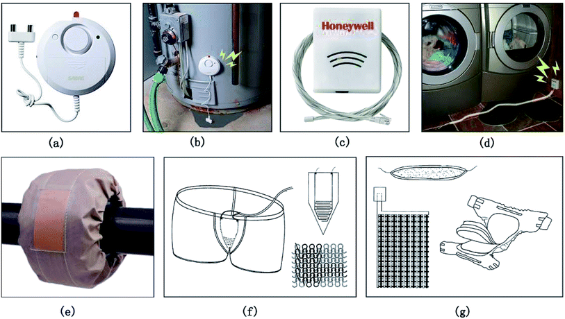
The leakage of liquids at trace level has to be detected and controlled for various applications including medical, industrial and civil.1–4 Sensors for conductive liquid leakage detection are very important for online monitoring systems due to their high efficiency and sensitivity.5,6 Commonly used sensors for conductive liquid leakage detection use a pair of stainless steel electrodes for measurement, as shown in Fig. 1a. It can be seen that the application of this kind of sensor is restricted since it can only detect large leaks and only can be used near the leak position, as presented in Fig. 1b. Furthermore, it can't be used for wearable sensing because of its stiffness and inflexibility. Therefore, development of sensors with higher sensitivity, faster response, better tailoring flexibility and larger detection area is an ongoing topic of intensive research.7,8Soft sensors based on textiles have gained increasing interest in recent years as they can be easily integrated due to the soft, flexible, lightweight and breathable characteristic of the textile, which enables them to be used to detect over larger areas and have wider applications from healthcare to sports, fashion and industrial activities.9–15 A modified textile based sensor is a cable type sensor as shown in Fig. 1c, which uses a cable as the detector and can monitor leak along its entire length. Seen from Fig. 1d, as a textile based sensor, the cable type sensor exhibits higher flexibility, sensitivity and reliability when use over a larger area. Besides, it can be cut without damaging its performance, showing good flexibility and adaptability. Despite of these advantages, it is insensitive to as few as one or two drops of water leakage. Obviously, this can be overcome by using a fabric based senor. Fig. 1e presents a flange shield in fabric form, which can be considered as a non-electrical output sensor. Apart from acts as a protector, it also can detect liquid leakage. With pH-indicating materials in it, the sleeve can detect small leaks of alkaline or acidic liquid by showing green or red color. Yet, disadvantages of this kind of flange sleeve are that it can neither detect neutral liquid leakage nor become one part of an online detecting system for its non-electrical output characteristic. By comparison, it is not hard to find that fabric based sensor for liquid detection is the best candidate for detection of liquids at trace level, and it shows the best adaptability.
Recently, an array of textile based sensors emerged with the rapid development of smart textiles.16–18 Fig. 1f shows a knitted fabric based humidity sensor from a Germany patent.19 Sensor is comprised of two grid-like electrodes knitted by conductive yarns in a special way. About the practice of the invention, the sensor is used to make incontinence underwear for patients. Fig. 1g is another humidity sensor invented by Korean researchers, which consists of two layers of electrodes and a moisture absorption layer between them, measuring moisture by detecting resistance and capacitance changes.20 Electrodes can be made of flexible textiles, such as woven or non-woven fabrics. With the use of textiles, the sensor can be used as intelligent diaper as the patent application introduced. Unfortunately, sensors mentioned above cannot be cut freely as they can not work after being cut for the reason that the pair of electrodes is placed at two sides. Failure to be cut will lead to some problems, such as the fabric must be customized according to the practical use of the sensor, the adaptability of the sensor is limited in the maintenance of the monitoring system. The solution is to place the two electrodes at the same side. However, in this case, the structure of the used fabric must be well designed to avoid contact between yarns that are contacted with the two electrodes, since which will bring about short circuit and consequently lead to breakdown of the sensor. Moreover, as we know, response speed is very important to evaluate detection performance of a sensor. Nevertheless, so far, to the best of our knowledge, research on response speed of the fabric based sensor has seldom been reported. Hence, the aim of this work is to develop a flexible woven fabric based highly sensitive sensor for conductive liquid leakage detection. In comparison to sensors introduced above, the fabricated sensor could quickly detect as little as one drop of liquid at anywhere in a large area. Furthermore, the fabricated sensor could be cut along its warp or weft direction without damaging its performance, which allowed it to be tailored flexibly for use. Also, the fabricated sensor could become one part of an online detecting system to monitor flange leakage at trace level, or could be made into wearable device to monitor patients' and babies' sweat and urine and wound bleeding.
2. Structure and working mechanism of the liquid sensing fabric
The structure of the fabricated conductive liquid sensing woven fabric was shown in Fig. 2a. In Fig. 2a, warp yarns A, B, C, D and weft yarns a, b, c, d were conductive yarns, while the rest of the yarns were nonconductive yarns. It could be seen that the warp yarn A contacted with weft yarns a and c while it was separated from weft yarns b and d, which resulted in the electrical current could go across the conductive path established by warp yarn A, weft yarns a and c rather than going across the open circuit that formed by warp yarn A, weft yarns b and d. Similarly, the electrical current could go across the conductive path established by warp yarn B, weft yarns b and d rather than going across the open circuit that formed by warp yarn B, weft yarns a and c. Therefore, there wouldn't be electrical connection between warp yarns A and B as well as between warp yarns C and D when the fabric was dry. Or else, the conductive path could be established between warp yarns A and B and between warp yarns C and D once the conductive liquid dropped (the elliptical shadow in Fig. 2) on the fabric, as shown in Fig. 2b. Two new fabrics could be obtained by cutting the fabric in Fig. 2a along its warp direction (Fig. 2c and d), both of which could be used for conductive liquid detection. Current flowing paths within them were also illustrated with arrows. Furthermore, the fabric in Fig. 2c was cut to acquire another fabric, which was shown in Fig. 2e. It could be seen that the newly acquired fabric still could detect conductive liquid effectively. Obviously, the fabric could be cut repeatedly without affecting its detection performance as long as warp yarns A and B or warp yarns C and D were left in it.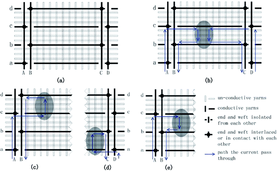 | ||
| Fig. 2 Structure and working mechanism of the fabric: the structure of the fabric (a), working mechanism of the fabric (b), (c), (d), (e). Fabrics in (c) and (d) are two new fabrics obtained by cutting the fabric in (a) along its warp direction. The fabric in (e) is another new fabric acquired by cutting the fabric in Fig. 2c. The elliptical shadow part denotes a drop of conductive liquid. Arrows indicates how the current flows. | ||
In general, warp yarns and weft yarns within a woven fabric either interlace or contact with each other. Even for fabrics with twill weave or satin weave, warp yarns and weft yarns within them are in contact with each other when they don't interlace with each other. In this case, paths established by warp yarns and weft yarns are all conductive if conductive yarns are adopted. Hence, the difficulty for fabricating a fabric with the structure shown in Fig. 2a is to achieve separations of warp yarns and weft yarns at particular points (for example, the intersection point of warp yarn B and weft yarn a) so as to establish open circuits in the fabric as designed.
3. Fabrication of the liquid sensing fabric
Nonconductive yarns (40S cotton yarn, 75D/48F polyester filament and 40S cotton/polyester blended yarn (65% cotton/35% polyester)) were supplied by Yancheng Yonghe Tex Co., Ltd, China. Conductive yarns 68D stainless steel wire 0.035 mm in diameter, 32S stainless steel blended yarn (30% stainless steel/70% polyester), 70D/36F silver plated multifilament, 75D/48F polyester interlaced yarn and wrapped yarn (obtained by wrapping the 70D/36F silver-plated multifilament on the 150D polyester filament) were supplied by Laiwu Longzhi Metal Yarn Co., Ltd, China. Various conductive liquid sensing fabrics were fabricated on an automatic sample rapier loom (SL7900, CCI Tech Inc.).As mentioned above, separations at specific intersection points of yarns in a single layer fabric couldn't be achieved. For this reason, a double layer structure was exploited for fabrication of the fabric, as shown in Fig. 3. It could be seen from Fig. 3a that weft yarn a was separated from warp yarn B due to the existence of warp yarns 1, 2 and 3. In this way, an open circuit was formed between weft yarn a and warp yarn B. Similarly, an open circuit was also established between weft yarn b and warp yarn A (Fig. 3b).
The above designed double layer structure was used in the selvages of the fabric. The body of the fabric employed the single layer structure presented in Fig. 2a, warp and weft yarns in which needed to be in close contact. In order to enhance the detecting performance of the fabricated fabric, the number of conductive warp yarns A, B, C, and D was increased from 1 to 5 respectively. Table 1 presents the fabrication conditions for the liquid sensing fabric. N and C were the nonconductive yarn and the conductive yarn, respectively. Fabric with wider width could be obtained by increasing the number of warp yarns in the body of the fabric. All fabric samples were produced according to the fabrication condition presented in Table 1, but with different yarns. Fig. 4 showed photographs of the fabric fabricated by using 40S cotton/polyester blended yarn (65% cotton/35% polyester) as nonconductive yarns and 70D/36F silver plated filaments as conductive yarns.
| Fabric | Arrangement of warp yarn | Arrangement of weft yarn | Fabric construction |
|---|---|---|---|
| Left selvage | 20N + (1C + 7N) × 5 + 16N + (4N + 1C + 3N) × 5 | 1C + 11N | Designed double layer structure |
| Right selvage | (4N + 1C + 3N) × 5 + 16N + (1C + 7N) × 5 + 20N | 1C + 11N | |
| Body | 200N | 1C + 11N | 2/2 twill |
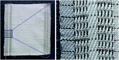 | ||
| Fig. 4 Photographs of the fabric fabricated by using 40S cotton/polyester blended yarn (65% cotton/35% polyester) as nonconductive yarns and 70D/36F silver plated filaments as conductive yarns. | ||
4. Conductive liquid sensing fabric sensor characterization
4.1 Structure observation
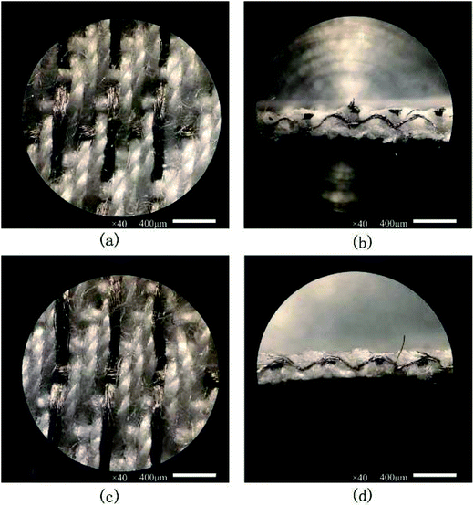
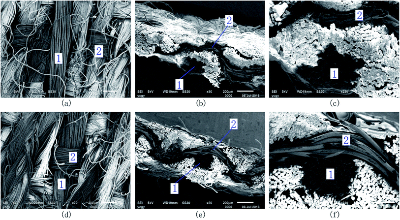
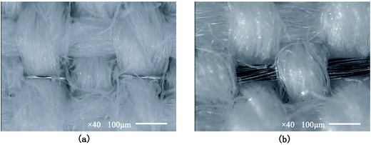
The structure of the surface and the cross section along the weft direction of the fabric were observed by OM (Optical Microscope) and SEM (Scanning Electron Microscopy). OM images of the fabric were shown in Fig. 5, in which yarns shined with metallic luster are silver plated filaments. Fig. 6 showed SEM images of the fabric. Yarns marked with number 1 and 2 were conductive filaments. Apparently, they showed a darker color, were not twisted and were composed of thicker single fibers.As shown in Fig. 5, yarns in the fabric arranged and interlaced exactly the same as that shown in Fig. 3. From Fig. 6, we could see that conductive warp yarns and weft yarns were well apart or in close contact at specific intersection points as designed, exhibiting good isolation property or large contacting surface.
4.2 Conductive liquid leakage detection measurement
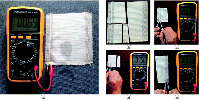
As we know, water is the most common liquid. Compare with acids, alkalis and salts, it shows weaker conductivity. The conductive liquid detection efficiency of the fabricated fabric was evaluated by investigating its water sensing performance. In particular, the resistance of the fabric when water dropped on it was compared with that when it was dry.Instruments and methods used for the test were shown in Fig. 7. The resistance of the fabric was measured by clamping the two groups of conductive warp yarns within one of the sledges through a pair of alligator clips of a multimeter.
The test involved two main steps: (1) measured the resistance of the fabric when it was dry, and (2) measured the resistance of the fabric after approximately 0.05 mL of water dropped on it (Fig. 7a). The second step was repeated until the whole fabric was tested all over, and the fabric needed to be dried using a hair drier after each measurement. After all this was done, the fabric was cut (Fig. 7b) into new fabrics to go on the same test.
Test results showed that electrical connection couldn't be formed in the fabric when it was dry. Once water dropped and spread on the fabric and was absorbed by it, conductive path can be established between warp yarn A and B and between warp yarn C and D. At this time, the resistance of the fabric decreased to as low as 100 kΩ, which usually is lower than 1 MΩ. The new fabrics acquired by cutting the original fabric were also confirmed to have the same property. The conductive liquid leakage detection progress of the fabric was shown in Video SI1 (ESI†).
Considering that the fabric based sensor need to be bendable to fit surfaces of adequate shapes, the detection performance of the fabric sensor under the bending state was tested. The above test was carried out by folding the fabric (folding width is 1 cm) at different angles to simulate various bending conditions that may occur in actual use. From Fig. 8, the resistance of the fabric under various bending conditions decreased to as low as 100–200 kΩ, which showed that the fabricated fabric based sensor still was workable even it bore considerable bending. This can be attributed to soft nature of the yarns and tension the yarns bore during the weaving process, which can promise tight interlacing of the yarns. Yarns in the fabric were in contact with each other even if the fabric was suffering from bending.
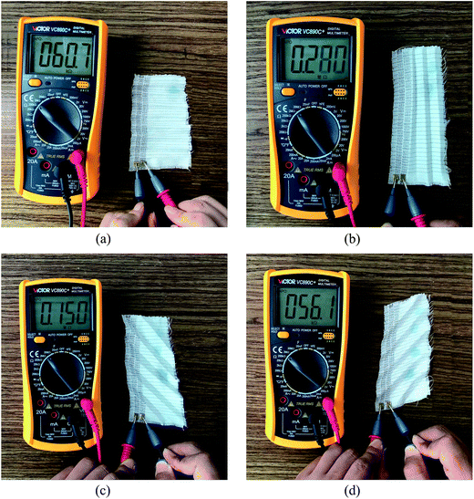 | ||
| Fig. 8 Resistance measurement of the fabric under various bending conditions by folding the fabric at 0° (a), 90° (b), 135° (c) and 45° (d). | ||
Evidently, the structure designed for fabrication of the fabric in this paper was proved to be feasible. Nevertheless, results implied that the fabric was not so responsive. Thus, further studies on the selection of yarns were carried out in this paper.
5. Selection of yarns
For industrial monitoring application purpose, the fabricated fabric should follow some objective features: (1) the resistance between the two groups of conductive warp yarns within one of the sledges should be infinite when the fabric is dry, (2) while water dropping on the fabric, the value should be as low as possible, which is better to be lower than 1 MΩ, and (3) the fabric can detect in short response time with resistance change occurs at the time the water drops on the fabric.Therefore, influences of different nonconductive and conductive yarn materials on the conductive property and the absorption property of the fabric were mainly analyzed. All following experiments were carried out using water as the conductive liquid, and a drop of water (still is about 0.05 mL) was used in all experiments related to fabrics.
5.1 Selection of nonconductive yarns
All of the conventional materials for yarn use such as cotton, wool, silk, linen and various commonly used chemical fibers display nonconductive feature when they are dry, and turn into conductive after absorbing water. Therefore, selection of nonconductive yarns was based on their conductivity after water absorption and their water absorption rate.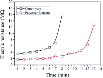 | ||
| Fig. 9 Resistance in MΩ of the 75D/48F polyester interlaced yarn and the 40S 100% cotton yarn in 1 cm length versus time in minutes after water absorption. | ||
As shown in Fig. 9, although resistance of the wet polyester interlaced yarn was smaller than that of the cotton yarn, resistances of them were still in the same order of magnitude. Therefore, other factors need to be furtherly considered on whether the polyester interlaced yarn is a superior choice.
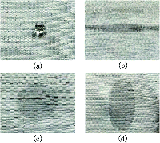
As shown in Fig. 10, the wettability of the four different kinds of fabrics decreased in the order of polyester warp/polyester weft (Fig. 10c) > polyester warp/cotton weft (Fig. 10d) > cotton warp/polyester weft (Fig. 10b) > cotton warp/cotton weft (Fig. 10a). The polyester warp/polyester weft fabric could even completely absorb the water in 5 seconds while the time needed for the polyester warp/cotton weft fabric was no more than 30 seconds. This could be attributed to the better wicking property of the polyester interlaced yarn, which could lead to a higher water absorption rate. The flat shaped water stain on the cotton warp/polyester weft fabric also confirmed the better wicking property of the polyester interlaced yarn. As stated above, it is better to select the polyester interlaced yarn as the nonconductive yarn, especially used as the nonconductive warp yarn.
5.2 Selection of conductive yarns
| Weft yarn type | Time (min) | |||||
|---|---|---|---|---|---|---|
| 1 | 2 | 3 | 4 | 5 | 6 | |
| Stainless steel wire | >20 | |||||
| Stainless steel blended yarn | >20 | |||||
| Silver plated multifilament | 0.11 | 0.15 | 0.18 | 0.20 | 1.25 | 5.02 |
Results implied that the stainless steel blended yarn and the stainless steel wire were not suitable to be used as the conductive weft yarn due to different reasons. For the stainless steel blended yarn, its resistance was great and was up to hundreds of kΩ per centimeter due to the dispersive distribution of the stainless steel short fiber in the blended yarn. For the stainless steel wire, although its resistance was low, its single existence and great stiffness (Fig. 11) led to the contact surface between it and the warp yarn was small, which resulted in great contact resistance between them.27,28 Additionally, the stainless steel wire was easily to be broken. Therefore, for the selection of the conductive weft yarn, the conductive multifilament or stranded metal wire should be adopted to get a lower contact resistance.
| Warp yarn type | Time (min) | |||||
|---|---|---|---|---|---|---|
| 1′ | 2′ | 3′ | 4′ | 5′ | 6′ | |
| Silver plated multifilament | 0.11 | 0.15 | 0.18 | 0.20 | 0.60 | 0.71 |
| Wrapped yarn | 0.42 | 0.10 | 0.16 | 0.13 | 0.11 | 0.11 |
Clearly, there was no significant difference between using the wrapped yarn and the silver plated multifilament if evaluate by whether the resistance was lower than 1 MΩ. This was because that the number of conductive yarns in the fabric were more than one, there always was silver plated multifilament which would contact with the conductive weft yarn.
Hence, the wrapped yarn obtained by wrapping the 70D/36F silver plated multifilament on the 150D polyester filament is superior to the silver plated multifilament to be used as the conductive warp yarn in term of the tensile strength and the weavability.
6. The detecting circuit
From the above results, we can see that although the conductivity of the fabric changed when water dropped on it, the resistance of the fabric was great and unstable, ranging from hundreds of kΩ to lower than 1 MΩ, which poses difficulties to detection. Therefore, the circuit of Fig. 12a was used in this paper. In the circuit, the IC LM393 is a voltage comparator. The transistor in LM393 output terminal will be in ‘off’ state when the voltage of non-inverting terminal (which usually named Vin+) is higher than that of inverting terminal (which usually named Vin−), otherwise the transistor will be in ‘on’ state. If the power Vcc is assumed as 5 V, Vin− will be 3.33 V. Vin+ will be greater than 3.33 V and >Vin− when the resistance between the two group warp yarns is greater than 4 MΩ. The output voltage Vo = Vcc = 5 V as the existence of the pull-up resistor. Conversely, Vin+ will be lower than 3.33 V and <Vin−, Vo = 0.3 V ≈ 0 V. For the fabricated fabric based sensor, electrical connection could not be formed in the fabric when it was dry and the resistance was greater than 500 MΩ (measured by a mega meter under 250 V for 1 minute). Once water dropped on the fabric, the initial resistance decreased to lower than 1 MΩ, which was far lower than 4 MΩ. Hence, as shown in Fig. 12b, the detecting circuit output a high level signal when the fabric was dry, the amplitude of which equaled to Vcc. Once water dropped on the fabric, the detecting circuit output a low level signal, the amplitude of which equaled to 0.3 V. The 2 M resistance in Fig. 12a was selected for it can improve reliability of the circuit. The IC LM393 was selected for it can work under a wide range of voltages with single or dual current source, and its typical input bias current can be as low as 25 nA. Results indicated that with the detecting circuit in Fig. 12a, and the conductive liquid sensing fabric could be very responsive to as little as one drop of water with good stability. The output signal can be applied to subordinate electronic devices such as MCU, PLC and so on, for that the LM393 is compatible with DTL, ECL, TTL, MOS, and CMOS logic levels. The above stated advantages are beneficial for efficiently setting up monitoring systems.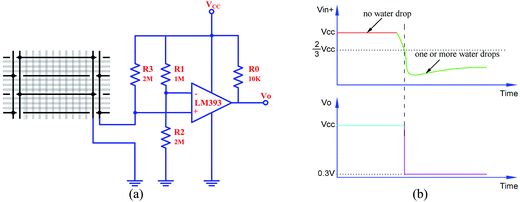 | ||
| Fig. 12 Composition and principle of the circuit: (a) detecting circuit, (b) working principle of the detecting circuit. | ||
7. Conclusions
A flexible woven fabric based highly sensitive sensor for conductive liquid leakage detection was developed in this paper. Comprehensive structure observation and property tests were carried out to improve its detecting performance. OM and SEM results showed that conductive warp yarns and weft yarns in the fabric with a double layer employed for its selvage were well apart at specific intersection points as designed, exhibiting good isolation property. Water sensing performance test showed that with the double layer structure, the fabric could be cut repeatedly without affecting its detection performance. Besides, further investigations on the selection of yarns were carried out. Results revealed that it was better to select the chemical multifilament as the nonconductive yarn for it could greatly shorten the response time of the fabric due to its better wicking property. For the selection of the conductive weft yarn, metal plated chemical multifilament was a better choice since its contact resistance with the wet warp yarns could be lower down. With a number of conductive warp yarns used in the fabric, wrapped yarn obtained by wrapping the conductive yarn on the nonconductive yarn should be selected as the conductive warp yarn for its higher tensile strength, which could reduce the weaving difficulty.A detecting circuit based on the dual differential compactor LM393 also was designed in this work, which could reliably detect the great and unstable resistance of the fabric after water absorption and output a signal compatible with other IC. The fabricated flexible woven fabric based sensor could quickly detect as little as one drop of liquid at anywhere in a large area and could be cut along its warp or weft direction without damaging its performance, which allowed it to be tailored flexibly for use. Also, the fabricated sensor could become one part of an online detecting system to monitor flange leakage at trace level, or could be made into wearable device to monitor patients' and babies' sweat and urine and wound bleeding.
Conflicts of interest
There are no conflicts to declare.Acknowledgements
This research is supported by the High Education Science Foundation of Jiangsu Province under Grants 16KJB540005. This work is also partially supported by Top-notch Academic Programs Project of Jiangsu Higher Education Institutions (TAPP PPZY2015C254), and a grant from the financial support by Jiangsu Overseas Research & Training Program for University Prominent Young & Middle-aged Teachers and Presidents (2014). The authors are grateful for the projects supported by the Open Project Program of Key Laboratory of Eco-textiles, Ministry of Education, Jiangnan University (No. KLET1601).Notes and references
- A. Sun, L. Huang and Y. Li, Sens. Actuators, B, 2009, 139, 543–547 CrossRef CAS.
- S. Aziz, D. E. Chang, Y. H. Doh, C. U. Kang and K. H. Choi, J. Electron. Mater., 2015, 44, 3992–3999 CrossRef CAS.
- S. Aziz, K. G. Bum, Y. J. Yang, B. S. Yang and C. U. Kang, Sens. Actuators, A, 2016, 246, 1–8 CrossRef CAS.
- M. Sajid, H. B. Kim, G. U. Siddiqui, K. H. Na and K. H. Choi, Sens. Actuators, A, 2017, 262, 68–77 CrossRef CAS.
- Z. Ahmad, Q. Zafar, K. Sulaiman, R. Akram and K. S. Karimov, Sensors, 2013, 13, 3615–3624 CrossRef CAS PubMed.
- H. B. Kim, M. Sajid, K. T. Kim, K. H. Na and K. H. Choi, Sens. Actuators, B, 2017, 252, 725–734 CrossRef CAS.
- T. A. Blank, L. P. Eksperiandova and K. N. Belikov, Sens. Actuators, B, 2016, 228, 416–442 CrossRef CAS.
- G. A. Eyebe, B. Bideau, N. Boubekeur c, É. Loranger and F. Domingue, Sens. Actuators, B, 2017, 245, 484–492 CrossRef.
- A. Arogbonlo, C. Usma, A. Z. Kouzani and I. Gibson, Procedia Technology, 2015, 20, 270–275 CrossRef.
- C. Usma, A. Z. Kouzani, J. J. C. Chua, A. Arogbonlo, S. Adams and I. Gibson, Procedia Technology, 2015, 20, 263–269 CrossRef.
- L. Capineri, Procedia Eng., 2014, 87, 724–727 CrossRef.
- W. Zeng, L. Shu, Q. Li, S. Chen, F. Wang and X. Tao, Adv. Mater., 2014, 26, 5310–5336 CrossRef CAS PubMed.
- S. Takamatsu, T. Lonjaret, E. Ismailova, A. Masuda, T. Itoh and G. G. Malliaras, Adv. Mater., 2016, 28, 4485–4488 CrossRef CAS PubMed.
- T. T. Yang, D. Xie, Z. H. Li and H. W. Zhu, Mater. Sci. Eng., 2017, 115, 1–37 Search PubMed.
- S. Patel, H. Park, P. Bonato, L. Chan and M. Rodgers, J. NeuroEng. Rehabil., 2012, 9, 1–17 CrossRef PubMed.
- J. R. Windmiller and J. Wang, Electroanalysis, 2013, 25, 29–46 CrossRef CAS.
- J. Tsang, PhD Dissertation, Poly U, Hongkong, 2007.
- M. Caldara, C. Colleoni, E. Guido, V. Re and G. Rosace, Sens. Actuators, B, 2016, 222, 213–220 CrossRef CAS.
- M. Klaus, J. Michael, F. C. Susanne, R. W. Von and O. Mike, Germany Patent, EP 2325360 B1, 2011.
- S. Y. Seo, Korean Patent, PCT/KR2008/002198, 30-10-2008.
- M. Yao, M. Y. Shi and S. C. Jiang, Journal of Northwest Institute of Textile Science and Technology, 2001, 58, 1–8 Search PubMed.
- M. Yao and M. Y. Shi, Journal of Northwest Institute of Textile Science and Technology, 2001, 58, 9–14 Search PubMed.
- M. W. Shi, Y. N. Chen and M. Yao, Journal of Northwest Institute of Textile Science and Technology, 2001, 58, 15–23 Search PubMed.
- H. X. Zhang, F. R. Liu, J. Wang and C. Y. Zhu, J. Text. Res., 2008, 29, 31–38 CAS.
- A. Bouazza, Geotext. Geomembranes, 2014, 42, 417–419 CrossRef.
- B. X. Ni and P. Zhang, Dye. Finish., 2014, 17, 35–39 Search PubMed.
- J. H. Hong, Z. J. Pan, Z. Wang, M. Yao, J. Chen and Y. X. Zhang, Sens. Actuators, A, 2016, 238, 307–316 CrossRef CAS.
- J. F. Wang, H. L. Long and J. C. Li, J. Donghua Univ., 2013, 39, 608–613 CAS.
Footnotes |
| † Electronic supplementary information (ESI) available. See DOI: 10.1039/c7ra07273b |
| ‡ These authors equally contributed to this work. |
| This journal is © The Royal Society of Chemistry 2017 |

