 Open Access Article
Creative Commons Attribution 3.0 Unported Licence
Mutual-stabilization in chemically bonded graphene oxide–TiO2 heterostructures synthesized by a sol–gel approach
Usuma Naknikham a,
Vittorio Boffa
 *a,
Giuliana Magnacca
 b,
Ang Qiao
 c,
Lars Rosgaard Jensend and
Yuanzheng Yue
 *ac
*ac
aDepartment of Chemistry and Bioscience, Aalborg University, 9220 Aalborg, Denmark. E-mail: vb@bio.aau.dk; yy@bio.aau.dk
bDipartimento di Chimica, NIS Centre, Universitá di Torino, 10125 Torino, Italy
cState Key Laboratory of Silicate Materials for Architectures, Wuhan University of Technology, Wuhan 430070, China
dDepartment of Materials and Production, Aalborg University, 9220 Aalborg, Denmark
First published on 23rd August 2017
Abstract
We study the structure of the photocatalytic graphene oxide–titanium dioxide (GO–TiO2) nanocomposites prepared by in situ sol–gel nucleation and growth of TiO2 on GO sheets. Fourier transform-infrared (FTIR) and X-ray photoelectron (XPS) spectra of these composites indicate that the GO sheets and the TiO2 nanoparticles interact through Ti–O–C bonds. This chemical interaction is strong enough to ensure mutual stabilization during thermal annealing, and thereby GO inhibits TiO2 crystallization. In addition, thermal reduction of GO nanoribbons anchored to TiO2 nanoparticles occurs at a higher temperature and with a lower released energy than in the pure GO powder. Understanding of the mutual-stabilization mechanisms is critical for the rational design of GO–TiO2 photocatalysts.
1. Introduction
The breakthroughs of graphene research have been revolutionizing many research fields owing to the superior physical and chemical properties of graphene-based materials over a broad application spectrum.1–3 For instance, graphene–TiO2 heterostructures have opened a new direction in the development of heterogeneous photocatalysts for environmental applications.4–6 Nowadays, the benchmark material for photocatalytic application is TiO2, because it is inexpensive, chemically inert and has high photocatalytic activity in the abatement of organic pollutants.7 However, the TiO2 efficiency is limited by high rate of electron–hole pair recombination and its band-gap can only be used to exploit UV-light.8–10 In principle, the combination of TiO2 and graphene allows for superior photocatalytic properties, because graphene can potentially act as electron acceptor for hindering electron–hole recombination and it can increase the absorption range from UV to visible light of TiO2.7,10,11 In addition, graphene can function as an absorbant,12 thus holding pollutants close to the TiO2 photocatalytic centers.2TiO2–graphene photocatalysts have recently attracted considerable interest and different methods have been established for their fabrication. Such methods often involve the synthesis or the deposition of TiO2 nanoparticles on water dispersed graphene oxide (GO) sheets. Indeed, the use of GO offers several advantages, because GO can be easily prepared by chemical oxidation and exfoliation of natural graphite,2,13 it can be easily dispersed in water, and it can subsequently be thermally or chemically reduced to graphene-like structures (rGO).12,14 Furthermore, in such heterostructures the interactions between GO functional groups and the surface of the nanoparticles are beneficial for integrating the respective merits and to solve compatibility problems during synthesis and post-treatment, thus yielding composites with enhanced properties.15,16
TiO2–rGO composites prepared by hydrothermal and solvothermal processes exhibit good chemical bonding at the interface.8,17 However, these methods work for specific conditions and equipment, e.g., in the cases of high temperature, Teflon autoclave or organic solvents.8,17,18 On the contrary, the sol–gel synthesis is simple, requires mild conditions, and makes it possible to obtain narrow size distributions in the nanometer range.19 In addition, controlling pH offers the possibility to exploit the strong electrostatic interaction between the negative charged GO sheets and the positively charged surface of TiO2 nanoparticles.11,19 For instance, Zhang et al. succeeded in synthesis of a GO–TiO2 intercalated composite by electrostatic attraction via a sol–gel process at 80 °C.20 [TiO]2+ was introduced into GO interlayer exfoliated in 0.2 M NaOH, so that the nucleation and growth of TiO2 crystal occurred in situ. The photo-degradation of methyl orange solution under UV light of this GO–TiO2 composite within 15 minutes (87.2%) was stronger than that of the reference Degussa P25 powder (38.4%). The interaction between GO and TiO2 nanoparticles can also be used to prepare stacked graphene membranes with photocatalytic properties,21–24 where the oxygen functional groups on GO interact with graphene sheets forming interlocked layers.25 Based on these heterostructures, the size of the TiO2 nanoparticles can be used to tune the space between GO layers and hence to control the membrane perm-selectivity.26 On the other hand, synthesis parameters can affect the morphology of titanium dioxide nanoparticles and the density of oxygen moieties on GO sheets, and hence, the photocatalytic performance and the processability of these materials. For instance, Lambert et al. prepared paper-like GO–TiO2 composites via hydrolysis of TiF4 at 60 °C for 24 hours.27 These composites showed the co-existence of highly oxidized graphene and TiO2 nanocrystals with anatase phase.
In this context, it is important to investigate how TiO2 nanoparticles and GO sheets can mutually influence their morphological evolution during synthesis and during thermal annealing. In a recent paper, Boffa et al. have demonstrated the ability of a waste-derived biopolymer, with functional group distribution similar to GO, to control the morphology of TiO2 nanoparticle during sol–gel synthesis.28 Therefore, we expect that the presence of GO will influence the formation and the growth of TiO2 nanoparticles during synthesis. In this work, TiO2 nanoparticles were synthetized via the sol–gel method, in the presence of GO sheets. pH was kept at 6 in all the syntheses, while synthesis temperature ranged between 60 °C to 100 °C. No synthesis above 100 °C was performed, to preserve the functional groups on graphene oxide,29 an important structural feature for the fabrication of photocatalytic membranes for the degradation water pollutants under the visible light. Moreover, this gave the opportunity to further investigate the behavior of such groups during thermal annealing. The loading of GO in the nanostructured materials was varied from 0 to 50 wt%, to study the concentration effect. All the syntheses were performed in 4 hours, except for one sample with 1 wt% GO loading, which was prepared in 24 hours at 100 °C. Thus, it was also possible to investigate the structural evolution of the materials for a long aging time.
2. Experimental section
2.1 GO preparation
All the chemicals used for the synthesis of the nanocomposites were purchased from Sigma-Aldrich, unless otherwise specified. GO was prepared via a modified Hummers methods.30 2.0 g natural graphite powder (Graphit Kropfmühl GmbH) was dispersed in concentrated H2SO4 solution (50 mL, 98%) in an ice bath. Then, 6.0 g potassium permanganate (KMnO4) was slowly added and the mixture was heated at 35 °C in an oil bath for 2 hours. After that, the suspension was cooled in an ice bath and 350 mL deionized water (DI) were slowly added. H2O2 solution (30%) was slowly dropped into the mixture until gas development stopped and the suspension became orange-yellow. All steps were done under continuous vigorous stirring. The precipitate was washed with DI water until pH of the supernatant become natural and was then freeze-dried to obtain a graphite oxide powder, which can be easily dispersed in water.2.2 Synthesis of the GO–TiO2 composites
TiO2 photocatalysts with theoretical GO loading of 0, 1 and 50 wt%, named T-4, 1GT-4 and 50GT-4, respectively, were synthesized. The ratios of TiCl4/GO/H2O in the synthetic mixtures were adjusted to obtain the desired GO loading and a total GO + TiO2 concentration of 2.5 g L−1. Firstly, graphite oxide powder was dispersed in 100 mL ultrapure water (resistivity ≥ 18 MΩ cm) in an ultrasonic bath for 30 minutes. After that, the suspension was stirred in an ice bath for 30 minutes. TiCl4 (98%) was added and stirred at 600 rpm for an hour, while heating was avoided by keeping the mixture in the ice bath. Then, the suspension was let to reach room temperature (∼22 °C) and the pH was adjusted with NH4OH solution (25%) to 6. pH was maintained at 6 for 2 hours, and then the mixture was heated at the target temperature of the synthesis in an oil bath for 4 hours under vigorous stirring. Synthesis temperatures ranged between 60 °C and 100 °C, as specified for each sample in the Results and discussion section. For one sample with 1 wt% GO loading, namely 1GT-24, the temperature was maintained at 100 °C for 24 hours. After synthesis, the suspensions were left to cool to reach room temperature while continuously stirring for 18 hours. After this, TiO2–GO nanocomposites were collected by centrifugation and cleaned with DI water until the silver nitrate test (0.1 M AgNO3 solution) on the washing solution was negative, i.e. no chloride ions were detected. Finally, the precipitation was washed with ethanol and dried in vacuum at 40 °C.2.3 Characterization of the GO–TiO2 composites
The structure of the samples was characterized by scanning electron microscope, SEM (Zeiss, 1540 XB). High-resolution transmission electron microscopy (HRTEM) images were obtained with a JEOL 3010-UHR instrument. The crystalline phase and the size of TiO2 nanoparticles, and the interlayer distance of GO were investigated using a PANanalytical Empyrean diffractometer, operating at 45 kV and 40 mA, with Cu Kα radiation (λ = 1.5418 Å). Both reflection spinner and SAXS stage were used. SAXS measurements were performed over a q interval included between 5.3 × 10⁻³ Å−1 and 3.5 × 10⁻¹ Å−1. After background subtraction, the scattered intensity I was plotted as a function of the scattering vector q, and the size distribution of the titania particles was obtained by fitting eqn (1) on the experimental data.
 | (1) |
 | (2) |
 | (3) |
Fourier transform-infrared spectroscopy, FTIR (Varian Cary®50 UV-Vis Spectrophotometer), was performed by using the KBr technique (KBr![[thin space (1/6-em)]](https://www.rsc.org/images/entities/char_2009.gif) :
:![[thin space (1/6-em)]](https://www.rsc.org/images/entities/char_2009.gif) sample = 100
sample = 100![[thin space (1/6-em)]](https://www.rsc.org/images/entities/char_2009.gif) :
:![[thin space (1/6-em)]](https://www.rsc.org/images/entities/char_2009.gif) 0.1) to investigate which type of functional groups was present in the nanocomposite materials, and the interaction between GO and TiO2. The measurement was conducted within the wave number interval 400–4000 cm−1 in transmittance mode. XPS spectra were obtained by an ESCALAB 250Xi X-ray photoelectron spectrometer (Thermo Fisher Scientific) using Al Kα radiation. RAMAN spectroscopic measurements were performed on an Invia RAMAN microspectrophotometer (Renishaw) in the backscattering geometry with λ = 532 nm. The thermal evolution of the photocatalysts was determined from 50 to 800 °C by differential scanning calorimetry and thermogravimetry (DSC/TG) over a NETZSCH STA 449 F1 Jupiter, at a heating rate of 10 °C per minute, with platinum crucible, and under argon atmosphere.
0.1) to investigate which type of functional groups was present in the nanocomposite materials, and the interaction between GO and TiO2. The measurement was conducted within the wave number interval 400–4000 cm−1 in transmittance mode. XPS spectra were obtained by an ESCALAB 250Xi X-ray photoelectron spectrometer (Thermo Fisher Scientific) using Al Kα radiation. RAMAN spectroscopic measurements were performed on an Invia RAMAN microspectrophotometer (Renishaw) in the backscattering geometry with λ = 532 nm. The thermal evolution of the photocatalysts was determined from 50 to 800 °C by differential scanning calorimetry and thermogravimetry (DSC/TG) over a NETZSCH STA 449 F1 Jupiter, at a heating rate of 10 °C per minute, with platinum crucible, and under argon atmosphere.
3. Results and discussion
3.1 Size and dispersion of TiO2 nanoparticles
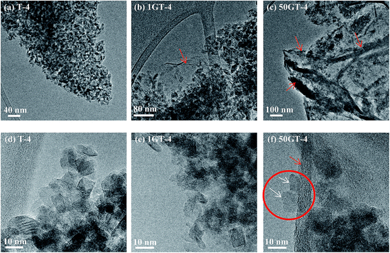
In this section, we present and discuss the structural features of a pure TiO2 reference sample synthetized in 4 hours (T-4), two TiO2 nanocomposites with 1 wt% GO loading synthetized in 4 hours and 24 hours (1GT-4 and 1GT-24 respectively), and a TiO2 nanocomposite with 50 wt% GO loading synthetized in 4 hours (50GT-4). For simplicity, these materials are hereafter referred according to the designations that are reported above.The morphology of the GO–TiO2 nanocomposites was investigated by electron microscopy. Fig. 1 shows the SEM images of the starting GO and of 50GT-4. The carbon layers of the starting GO forms an open sponge-like structure (Fig. 1(a)), as typical of freeze-dried GO.37 50GT-4 consists of TiO2 particles with size of a few nanometers, which are packed into large agglomerates, either covering or intercalating GO sheets, thus making GO structures not visible at SEM. No structural differences between the samples prepared in the presence of GO and the pure TiO2 reference were observed. Therefore, size and dispersion of TiO2 particles in the GO–TiO2 nanocomposites were investigated by HR-TEM analysis, as shown in Fig. 2. Fig. 2(a) shows highly agglomerated TiO2 nanocrystals in the T-4 sample. The high magnification micrograph in Fig. 2(d) confirms that these crystals have size of few nanometers and shows that they have polyhedral shape. Fig. 2(b) shows a micrograph of the 1GT-4 powder. Also in this case, TiO2 nanocrystals are highly agglomerated; but they anchor over an isolated GO sheet (red arrow) and partially cover it. In the case of the sample prepared with 50 wt% GO loading, namely 50GT-4, TiO2 nanoparticles are less agglomerated than in the other samples and decorate GO ribbons (Fig. 2(c)). The fingerprint of both TiO2 and GO ribbons are visible in Fig. 2(f), where we can observe two TiO2 crystallites (white arrows) laying with one of their facet over a 5–10 nm thick GO ribbons (red circle). Such GO ribbons are typical of GO-based materials,29 but were not found in the micrographs of 1GT-4 (Fig. 2(b) and (e)). This could be ascribed to the fact that, at low GO loading, TiO2 nanoparticles can fully intercalate GO sheets (see the red arrow in Fig. 2(b)), thus avoiding the formation of GO nanoribbons. The high magnification micrographs (Fig. 2(d)–(f)) show that all the samples are made of crystalline particles (as evidenced by the presence of interference fringes) with polyhedral shape and size around 7–10 nm.
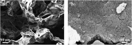 | ||
| Fig. 1 SEM images of (a) the freeze-dried GO and (b) the nanocomposite prepared with 50 wt% of GO, at 100 °C, for 4 hours (50GT-4). | ||
The size distribution of TiO2 particles in T-4, 1GT-4, 1GT-24 and 50GT-4 was measured by SAXS. The scattering curves (Fig. 3(a)) were analyzed in terms of size distribution functions, Dv(R), which are depicted in Fig. 3(b). The distribution is in agreement with that of the particles observed at HR-TEM. The particles are smaller than 20 nm with average diameter, dSAXS, ranging between 7.6 and 9.0 nm. Nevertheless, dSAXS of T-4 is 8.6 nm, which is larger than that of the TiO2 particles prepared in the presence of GO. This can be explained by considering that GO sheets contains a large number of oxygen functional groups which can interact with Ti4+ ions and titania cluster. Thus, they act as nucleation sites around which titanium dioxide nanoparticles grow during synthesis.27,28,38 The presence of a large number of such nucleation sites over GO sheets results in a smaller particle size for 1GT-4 and 50GT-4, compared to T-4. At 1 wt% of GO loading, only after 24 hours of reaction time (1GT-24), TiO2 particles reach a size comparable to those in the T-4 sample. Surprisingly, 1GT-4 and 50GT-4 have similar particle size distribution with both dSAXS = 7.6 nm, suggesting that the GO concentration in the reaction mixture has a negligible impact on the size of TiO2 nanoparticles. However, this result can be explained by considering: (i) the high density of oxygen functions on the GO sheets, and (ii) the lower exposure of the GO functional groups in the sample prepared with the 50 wt% GO loading. Indeed, as shown by Fig. 2, GO sheets in 1GT-4 are well intercalated by the TiO2 nanoparticles, while in 50GT-4, GO sheets form staked nanoribbon structures, resulting in a much lower exposure of the GO functional groups to the interaction with TiO2 clusters and particles.
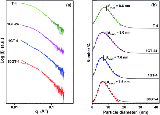 | ||
| Fig. 3 (a) SAXS curves and (b) correspondent TiO2 particle size distribution of the GO–TiO2 composites. The dots indicate the Dv(R) distribution functions31,32 and the lines correspond to the log–normal distributions. The average particle diameters, dSAXS, were calculated from the Dv(R) distribution functions. | ||
3.2 Order/disorder in the TiO2–GO nanocomposites
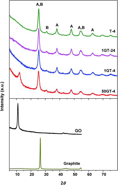
The morphology of GO and the composite materials was further investigated by XRD analysis. Fig. 4 shows the XRD patterns of bare GO, pure TiO2, and TiO2–GO composites. The starting GO shows a peak at 2θ = 10.46°,39,40 which corresponds to a d-space distance of 8.45 Å, and is consistent with the staking of highly oxidized graphene sheets. The characteristic GO peak is not visible in the powders prepared with 1 wt% GO loading. This observation matches with the HR-TEM micrographs of 1GT-4, where no GO layered structure was found, although the presence of such structures cannot be completely excluded. The diffraction is relatively weak because the amount of GO in this material is rather low.12,41 On the contrary, the characteristic GO peak is clearly visible in the diffractogram of the 50GT-4 powder, indicating restacking of GO layers in this material.27 However, the peak is broader than the one of the pristine GO and its maximum is shifted towards a higher 2θ value, namely 12.01° (d-space = 7.36 Å). As discussed later, a decrease of the interlayer distance is an indication of the partial reduction of the oxygen groups during synthesis. The FWHM (full width at half maximum) of the peaks was used to calculate the thickness of the stacked GO domains by the Scherrer equation. Scherrer distances of 24 nm and 9.2 nm were obtained for the starting GO and 50GT-4, respectively. In the case of 50GT-4, the distance corresponds to staking of about 12.5 GO layers and is consistent with the HR-TEM micrographs reported in Fig. 2(c) and (f). Moreover, TiO2 nanoparticles are expected to disrupt the parallel stacking of graphene oxide layers, thus resulting in a shorter Scherrer distance for 50GT-4 than for the pristine GO powder. XRD analysis was also used to investigate the crystal structure of TiO2 nanoparticles in the GO–TiO2 nanocomposites and in the T-4 reference. All the diffractograms show the characteristic peak of the anatase phase (A) and the peaks of the brookite (B) phase, but with a lower intensity. The average size of the anatase crystallites was calculated from the FWHM of the peak at 2θ ∼ 25.2°, obtaining the values of 6.4, 6.6, 7.4 and 8.3 nm for 50GT-4, 1GT-4, T-4, and 1GT-24, respectively. Despite 7–12% smaller than the average particle size measured by SAXS, they follow the same trend.3.3 GO functional groups
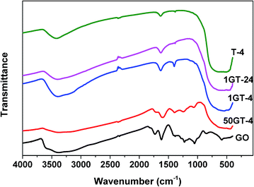
The FTIR spectra of GO, TiO2 and their composites are depicted in Fig. 5. The spectrum of the sample T-4 shows a broad peak below 750 cm−1 corresponding to Ti–O–Ti bonding and two peaks at 1630 and 1385 cm−1, which can be attributed to O–H vibration and Ti–O stretching modes, respectively.4 The starting GO sample shows a more complex spectrum, owing to various types of oxygen functional groups: C![[double bond, length as m-dash]](https://www.rsc.org/images/entities/char_e001.gif) O stretching (carbonyl) around 1731 cm−1, water –OH bending and –OH (hydroxyl) at 1618 cm−1, C–O–H (carboxyl) at 1384 cm−1, C–O (epoxy) at 1224 cm−1, –OH stretching (phenolic) at 1170 cm−1, C–O stretching (hydroxyl) at 1051 cm−1, C–H (aromatic) at 856 cm−1.4,42 These vibration modes are also observed for the sample 50GT-4, but with a lower intensity, as expected due to the lower concentration of GO in the sample. Degradation of the GO functional groups during synthesis is also possible, as discussed later. Moreover, the appearance of the broad peak around 400–750 cm−1 suggests that both Ti–O–Ti and Ti–O–C bonding are present in this sample. Indeed, Ti–O–C can be formed by condensation of the hydroxyl group of TiO2 and functional groups of GO.43 The spectra of the two composites with 1 wt% GO loading, namely 1GT-4 and 1GT-24, do not show the characteristic GO peaks, due to the low amount of GO. On the contrary, these samples show only the vibration modes observed for TiO2. Nevertheless, a broad band at 400–750 cm−1 (Ti–O–Ti and Ti–O–C) is also observed for these two samples.
O stretching (carbonyl) around 1731 cm−1, water –OH bending and –OH (hydroxyl) at 1618 cm−1, C–O–H (carboxyl) at 1384 cm−1, C–O (epoxy) at 1224 cm−1, –OH stretching (phenolic) at 1170 cm−1, C–O stretching (hydroxyl) at 1051 cm−1, C–H (aromatic) at 856 cm−1.4,42 These vibration modes are also observed for the sample 50GT-4, but with a lower intensity, as expected due to the lower concentration of GO in the sample. Degradation of the GO functional groups during synthesis is also possible, as discussed later. Moreover, the appearance of the broad peak around 400–750 cm−1 suggests that both Ti–O–Ti and Ti–O–C bonding are present in this sample. Indeed, Ti–O–C can be formed by condensation of the hydroxyl group of TiO2 and functional groups of GO.43 The spectra of the two composites with 1 wt% GO loading, namely 1GT-4 and 1GT-24, do not show the characteristic GO peaks, due to the low amount of GO. On the contrary, these samples show only the vibration modes observed for TiO2. Nevertheless, a broad band at 400–750 cm−1 (Ti–O–Ti and Ti–O–C) is also observed for these two samples.
The Raman spectra of starting GO and the nanocomposite samples are depicted in Fig. 6. They show the characteristic D (sp3 carbon) and G (sp2 carbon) band of graphene oxide at about 1350 and 1600 cm−1, respectively.13,44 The presence of both bands in 1GT-4 and 1GT-24 indicates the existence of graphene oxide in both samples. The G band is assigned to the in-plane vibrations of the graphene network, whereas the D band is due to out of plane vibrations attributed to the presence of structural defects. The intensity ratio of D and G bands (ID/IG) of 50GT-4, 1GT-4 and 1GT-24 are 0.98, 1.06 and 1.09, respectively. These values are higher than that measured for the starting GO (0.92). An increased ID/IG ratio has been typically observed after GO reduction, which could be attributed to the decrease in the average size of the sp2 domains in the 2D carbon network.13,25,45 Therefore, this implies a partial reduction and an increase in defects after attachment with TiO2 nanoparticles.
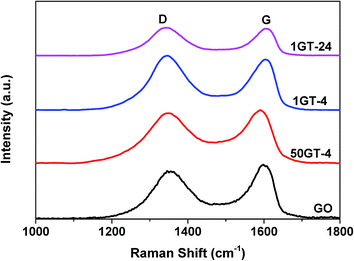 | ||
| Fig. 6 Raman spectra of GO and GO–TiO2 composites from 100–1800 cm−1; D and G band corresponding to sp3 and sp2 carbon, respectively. | ||
The partial reduction of GO during synthesis is confirmed by the XPS C1s spectra in Fig. 7(a). Peak deconvolution for the pure GO sample allows to distinguish the graphitic sp2 carbon atoms with binding energy at around 284.6 eV and the two types of oxidized carbon atoms C–O and C![[double bond, length as m-dash]](https://www.rsc.org/images/entities/char_e001.gif) O (or O–C
O (or O–C![[double bond, length as m-dash]](https://www.rsc.org/images/entities/char_e001.gif) O) with binding energy at 286.5 and 287.7 eV, respectively.46 The peak deconvolution for the spectra of 50GT-4, 1GT-4, and 1GT-24, shows the existence of carbon with different oxidation states in all the nanocomposite materials. The partial reduction of graphene oxide was confirmed by calculating the area ratios of the peak corresponding to the oxidized carbon over the peak of the fully reduced carbon atoms: AC–O/AC–C and AO–C
O) with binding energy at 286.5 and 287.7 eV, respectively.46 The peak deconvolution for the spectra of 50GT-4, 1GT-4, and 1GT-24, shows the existence of carbon with different oxidation states in all the nanocomposite materials. The partial reduction of graphene oxide was confirmed by calculating the area ratios of the peak corresponding to the oxidized carbon over the peak of the fully reduced carbon atoms: AC–O/AC–C and AO–C![[double bond, length as m-dash]](https://www.rsc.org/images/entities/char_e001.gif) O/AC–C.4 The results are reported in Table 1. The AC–O/AC–C and AO–C
O/AC–C.4 The results are reported in Table 1. The AC–O/AC–C and AO–C![[double bond, length as m-dash]](https://www.rsc.org/images/entities/char_e001.gif) O/AC–C values of all the GO–TiO2 nanocomposites are about 50% lower than those of the starting GO, meaning that a half of the oxygen-containing groups on GO was removed after decoration with TiO2 and heating at 100 °C. In addition, the synthesis time (4 hours or 24 hours) appears to have no influence on the GO reduction. Moreover, the binding energy of the peak corresponding to most oxidized carbon atoms shift from 287.7 eV for the pure GO sample to 289.3 eV for the two TiO2 powders containing the 1 wt% GO, thus suggesting by the formation of coordination structure in these materials,17,47 i.e. the formation of Ti–O–C moieties. This shift is less pronounced for 50GT-4 (binding energy = 287.9 eV), as a consequence of the formation of GO nanoribbons and the lower exposure of the GO functional groups to the interaction with TiO2 nanoparticles.
O/AC–C values of all the GO–TiO2 nanocomposites are about 50% lower than those of the starting GO, meaning that a half of the oxygen-containing groups on GO was removed after decoration with TiO2 and heating at 100 °C. In addition, the synthesis time (4 hours or 24 hours) appears to have no influence on the GO reduction. Moreover, the binding energy of the peak corresponding to most oxidized carbon atoms shift from 287.7 eV for the pure GO sample to 289.3 eV for the two TiO2 powders containing the 1 wt% GO, thus suggesting by the formation of coordination structure in these materials,17,47 i.e. the formation of Ti–O–C moieties. This shift is less pronounced for 50GT-4 (binding energy = 287.9 eV), as a consequence of the formation of GO nanoribbons and the lower exposure of the GO functional groups to the interaction with TiO2 nanoparticles.
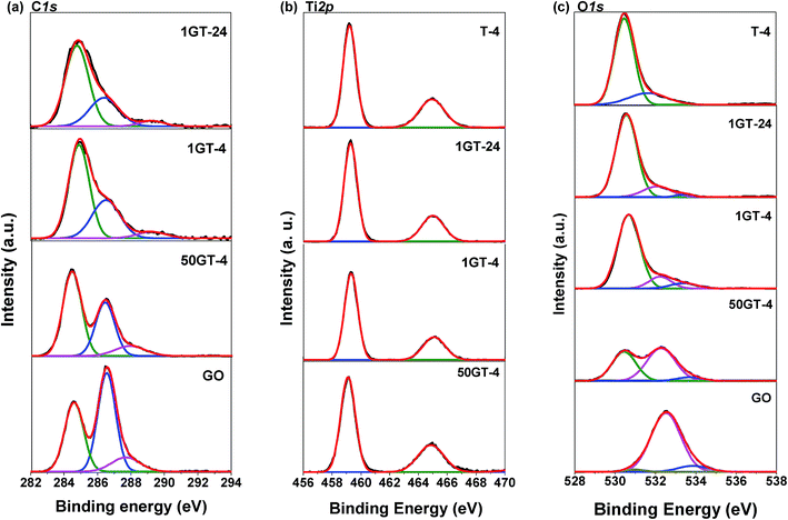 | ||
| Fig. 7 XPS spectra of GO, T-4, and GO–TiO2 composites: (a) C1s spectra, (b) Ti2p spectra, and (c) O1s spectra. | ||
![[double bond, length as m-dash]](https://www.rsc.org/images/entities/char_e001.gif) O/AC–C) of GO, 50GT-4, 1GT-4 and 1GT-24
O/AC–C) of GO, 50GT-4, 1GT-4 and 1GT-24
| Sample name | AC–O/AC–C | AO–C![[double bond, length as m-dash]](https://www.rsc.org/images/entities/char_e001.gif) O/AC–C O/AC–C |
|---|---|---|
| GO | 1.34 | 0.41 |
| 50GT-4 | 0.65 | 0.26 |
| 1GT-4 | 0.54 | 0.27 |
| 1GT-24 | 0.44 | 0.28 |
In Fig. 7(b), the Ti2p spectra of all the samples show two main peaks around 459.2 and 464.9 eV, with a splitting energy of 5.7 eV, assigned to Ti2p1/2 and Ti2p3/2 spin–orbital splitting photoelectrons of Ti4+, respectively.25,48 As expected for GO–TiO2 nanocomposites prepared under mild conditions, these spectra exclude the presence of Ti–C bonds, since there are no deconvoluted peaks at around 466.0 and 460.3 eV.49
The 3 fitted peaks of O1s show in Fig. 7(c). The OC![[double bond, length as m-dash]](https://www.rsc.org/images/entities/char_e001.gif) O and C
O and C![[double bond, length as m-dash]](https://www.rsc.org/images/entities/char_e001.gif) O, C–OH and CO–H of GO are at 530.9, 532.5 and 533.9 eV, respectively.50 The pure TiO2 shows characteristic Ti–O–Ti peak at 529.8 eV and the surface Ti–OH bond at 530.5 eV.50 The peaks at around 530.5, 532.2 and 533.5 eV are assigned to Ti–O–C,51 O–C, and –OH vibration modes,25,50 respectively, indicating the existence of the Ti–O–C linkage in the TiO2–GO nanocomposites. This is an important feature since Ti–O–C linkage may promote the electron transfer from the TiO2 nanoparticles to graphene structures during photocatalytic applications,25 and impact their mutual evolution during synthesis and thermal annealing.
O, C–OH and CO–H of GO are at 530.9, 532.5 and 533.9 eV, respectively.50 The pure TiO2 shows characteristic Ti–O–Ti peak at 529.8 eV and the surface Ti–OH bond at 530.5 eV.50 The peaks at around 530.5, 532.2 and 533.5 eV are assigned to Ti–O–C,51 O–C, and –OH vibration modes,25,50 respectively, indicating the existence of the Ti–O–C linkage in the TiO2–GO nanocomposites. This is an important feature since Ti–O–C linkage may promote the electron transfer from the TiO2 nanoparticles to graphene structures during photocatalytic applications,25 and impact their mutual evolution during synthesis and thermal annealing.
3.4 Synthesis temperature
By considering the morphology of GO–TiO2 nanocomposites with different compositions (see above), we investigate the effect of the synthesis temperature on the structural evolution during annealing of the nanocomposite with 50 wt% GO loading and the pure TiO2 reference. Fig. 8(a) shows the XRD patterns of the pristine TiO2 references (T-4) prepared at 60 °C and 100 °C, and the 50GT samples synthetizes at a temperature ranging from 60 °C to 100 °C. All 50GT-4 nanocomposites exhibit the characteristic GO peak, which allows for calculating the interlayer distance and the average thickness of the GO nanoribbons in the composite materials by using the Bragg law and the Scherrer equation, respectively. Fig. 8(b) shows that the interlayer distance for GO sheets in the samples prepared between 60 °C and 80 °C is 8.1 Å. This distance is close to that measured for the pristine GO powder (8.4 Å), but larger than the value of 7.36 Å measured for the composite prepared at 100 °C. Thus, the decrease of the interlayer distance results in thinner GO ribbons. | ||
| Fig. 8 (a) XRD patterns of 50GT and T-4 synthetized in 4 hours at a temperature between 60 °C and 100 °C. The letter “G” indicates the peak characteristic of graphene oxide. “A” and “B” indicate the characteristic peaks of anatase and brookite phases, respectively. (b) The characteristic peak of graphene oxide was used to calculate the distance between GO sheets (Bragg) and the average thickness of the GO nanoribbons (Scherrer) in the nanocomposites. (c) The characteristic peaks of TiO2 were used to calculate the size of the anatase crystallites (Scherrer) and the anatase fraction, WA (eqn (3) in the Experimental section). | ||
The samples synthetized at 60 °C appear to consist of amorphous TiO2 (both T-4 and 50GT-4), as shows in Fig. 8(a). The main phase, anatase, is present from 70 °C, while the presence of brookite is observed in the sample synthetized at 80 °C. Under these conditions (pH ∼ 6 and synthesis temperature > 70 °C), the formation of both phases has already been reported in literature.52–54 Titania characteristic peaks were used to calculate the size of anatase crystals and their fraction in the total crystalline phase. Nevertheless, we observe that the fraction of anatase phase, calculated as described in the Experimental section, increases with the temperature. Indeed, both pure TiO2 and GO–TiO2 composites prepared at 100 °C contain slightly more than 70% of anatase phase, while for the 50GT-4 sample prepared at 80 °C the fraction of anatase phase was calculated to be around 65%. The presence of GO in the reaction mixture has a significant role in influencing the size and agglomeration of the TiO2 nanoparticles, but it does not affect the anatase/brookite ratio. As expected, the average size of anatase crystallites increases with the temperature, e.g., from 4.1 nm for the 50GT sample prepared at 60 °C to 6.4 nm for the one prepared at 100 °C.
3.5 Thermal annealing
The mass loss during annealing of TiO2 and 50GT-4 synthetized at various temperatures is analyzed and the curves are shown in Fig. 9(a). As typical of GO-based materials, TG curves show three main steps of mass change. The mass loss of GO and the composites below 150 °C is due to the evaporation of physisorbed and nanoconfined water.55 The major loss of the mass is due to the degradation of the functional groups on graphene oxide at 150–350 °C: (i) H2O release through the dehydration of the neighboring hydroxyl groups and (ii) releasing of CO and CO2 from the decarbonation reaction.55 The last step, above 350 °C, has been assigned to the carbon network degradation25,56 and to the removal of the most stable oxygen functionalities.57 The mass loss of TiO2 synthetized in 4 hours at 60 °C and 100 °C is depicted in Fig. 9(b). Also in this case, physisorbed water evaporates below 150 °C.58 As expected, above this temperature there are only little changes in chemical composition,54 and mass loss is not observed toward until 800 °C. The data in Fig. 9(a) and (b) were used to calculate the theoretical mass loss of a 50![[thin space (1/6-em)]](https://www.rsc.org/images/entities/char_2009.gif) :
:![[thin space (1/6-em)]](https://www.rsc.org/images/entities/char_2009.gif) 50 w/w physical mixture of graphene oxide–TiO2 and the results are compared with the TG analysis of the 50TG samples in Fig. 9(c). In the 150–350 °C range, the mass loss of the composites is lower than that of a physical mixture of graphene oxide and TiO2. This is again a strong indication of chemical bonding between GO and TiO2,25 i.e. the condensation of oxygen functional groups on GO and hydroxyl groups on titania particles to form Ti–O–C.1
50 w/w physical mixture of graphene oxide–TiO2 and the results are compared with the TG analysis of the 50TG samples in Fig. 9(c). In the 150–350 °C range, the mass loss of the composites is lower than that of a physical mixture of graphene oxide and TiO2. This is again a strong indication of chemical bonding between GO and TiO2,25 i.e. the condensation of oxygen functional groups on GO and hydroxyl groups on titania particles to form Ti–O–C.1
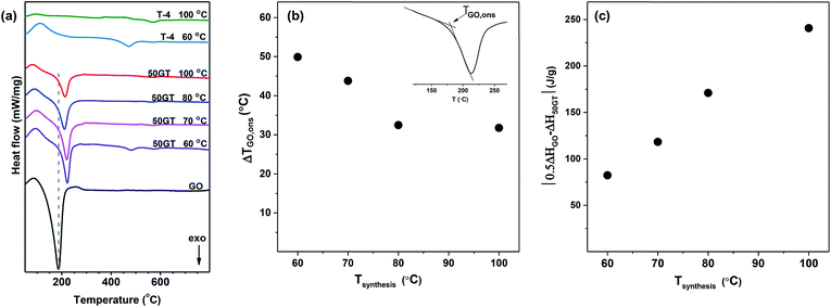
The DSC results in Fig. 10(a) show the exothermic transitions of GO, TiO2 and their composites (50GT 60 °C, 50GT 70 °C, 50GT 80 °C and 50GT 100 °C). The pure GO powder shows the typical exothermic sharp peak with onset temperature (TGO,ons) at 149 °C and minimum temperature (TGO,min) at 187 °C, which is due to the reduction reaction of the oxygen functional groups.59 The 50GT composites also display the characteristic peak, but surprisingly their TGO,ons and TGO,min shift toward higher temperatures (Table 2). The difference in reduction onset temperature, ΔTGO,ons, is plotted as a function of the synthesis temperature in Fig. 10(b). The highest ΔTGO,ons value, namely 49.9 °C, is observed for the sample prepared at 60 °C. ΔTGO,ons drops down to ∼32 °C with increasing the synthesis temperature for the 50GT powders prepared at 80 °C and 100 °C. This is again an indication of the chemical interaction between GO and TiO2. GO rearrangement in the more stable and ordered reduced structure is hindered by the fact that TiO2 nanoparticles are chemically anchored over the surface of the thin GO ribbons.27 The shift of TGO,ons from 149 °C of starting GO to over 180 °C in the composite samples suggests that titanium dioxide can retard the degradation of the functional groups on graphene oxide, because the condensation reaction between moieties on graphene oxide and titanium dioxide leads to stabilization of oxygen functional groups.1 The 50GT samples prepared at lower temperatures are highly amorphous and have small particle size. Therefore, they possess a high surface area and high defect density to interact with GO.
| Sample name | TGO,ons (°C) | TGO,min (°C) | ΔH (J g−1) at 180–220 °C |
|---|---|---|---|
| 50GT 100 °C | 180.9 | 213.1 | −299.6 |
| 50GT 80 °C | 181.6 | 193.1 | −369.4 |
| 50GT 70 °C | 192.9 | 220.7 | −422.1 |
| 50GT 60 °C | 199.0 | 222.2 | −458.2 |
| GO | 149.1 | 186.7 | −1081.0 |
The peak areas in Fig. 10(a) clearly indicate that the synthesis temperature has an impact also on the enthalpy associated with the reduction of GO. Indeed, the reduction enthalpy values reported in Table 2 clearly show that enthalpy decreases with the reaction temperature. Therefore, the difference between reduction enthalpy of the 50GT composite (ΔH50GT) and the theoretical reduction enthalpy of a physical mixture containing 50 wt% GO (0.5ΔHGO) is plotted as a function of the synthesis temperature in Fig. 10(c). The different trend can be attributed to the fact that the TiO2 nanocrystals present in the sample prepared at high temperature disrupt the order of the reduced graphitic structure.60
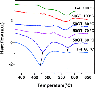
Fig. 11 shows the differential scanning calorimetry curves in the temperature range of 350–650 °C of 50GT and T-4 synthetized for 4 hours between 60 °C and 100 °C. The peaks for both the amorphous TiO2-to-anatase and the anatase-to-rutile transformations can be observed at around 470 °C and 570 °C in T-4 60 °C, respectively.61 In contrast, T-4 100 °C shows a transformation peak of anatase to rutile at 570 °C.50 The behavior of 50GT 60 °C at 400–650 °C is alike the one of T-4 60 °C. However, the anatase formation from amorphous phase of 50GT 60 °C occurs at a temperature about 10 °C higher than that of T-4 60 °C. On the contrary, the calorimetric scansions of the composites synthesized at 70–100 °C show only a weak hump at 570 °C for the anatase-to-rutile transition.
4. Conclusions
In this work, we study the structural evolution of GO–TiO2 composites during synthesis and thermal annealing. We have found experimental evidence for the interface chemical bonding between TiO2 nanoparticles and GO, even when a simple synthetic method is used under mild conditions, namely at pH 6 and at temperature between 60 °C and 100 °C. Using this method, the anatase–brookite mixed phase has been obtained, which is dispersed on GO monolayers for a low amount of GO (1 wt%), but decorates GO nanoribbons for a high amount of GO (50 wt%). TEM analysis shows facets of TiO2 nanocrystals laying on the GO nanoribbon, thus suggesting a strong interaction between the two materials. FTIR and XPS analyses suggest the formation of Ti–O–C interactions. The Ti2p XPS spectra exclude the formation of a significant number of Ti–C bonds, but the interaction between GO and TiO2 is strong enough to induce mutual shaping during synthesis and the thermal evolution.The role of GO on TiO2 morphology is summarized as follows: (i) GO affects TiO2 particle size and dispersion, since GO prevents agglomeration. However, GO does not influence type of phase or phase fraction of TiO2. (ii) GO retards the thermal transition from amorphous TiO2 to anatase phase.
The presence of TiO2 nanoparticles influences the GO morphology as follows: (i) TiO2 nanoparticles intercalate GO sheets, depending on the GO/TiO2 ratio. It is possible to obtain GO nanoribbons or isolated GO sheet. (ii) When GO nanoribbons are decorated with TiO2 nanoparticle, their thermal reduction occurs at a higher temperature than the pure GO powder.
Thus, this work gives new insights into the mutual shaping of TiO2 and GO during sol–gel synthesis and thermal annealing, and hence, enables rational design of new photocatalysts with desired morphology and performances.
Conflicts of interest
There are no conflicts to declare.Acknowledgements
The authors gratefully acknowledge financial support from the Thai Ministry of Science and Technology and the European Union project H2020-MSCA-RISE-2014, no. 645551. Fondazione San Paolo and Turin University are acknowledged for funding the project Microbusters (Progetto d'Ateneo 2014).References
- L. M. Pastrana-Martínez, S. Morales-Torres, V. Likodimos, J. L. Figueiredo, J. L. Faria, P. Falaras and A. M. T. Silva, Appl. Catal., B, 2012, 123–124, 241–256 CrossRef.
- N. Zhang, M.-Q. Yang, S. Liu, Y. Sun and Y.-J. Xu, Chem. Rev., 2015, 115, 10307–10377 CrossRef CAS PubMed.
- R. Sadri, K. Z. Kamali, M. Hosseini, N. Zubir, S. N. Kazi, G. Ahmadi, M. Dahari, N. M. Huang and A. M. Golsheikh, J. Dispersion Sci. Technol., 2017, 38, 1302–1310 CrossRef CAS.
- L. Zhang, Q. Zhang, H. Xie, J. Guo, H. Lyu, Y. Li, Z. Sun, H. Wang and Z. Guo, Appl. Catal., B, 2017, 201, 470–478 CrossRef CAS.
- R. K. Upadhyay, N. Soin and S. S. Roy, RSC Adv., 2013, 4, 3823–3851 RSC.
- M. Faraldos and A. Bahamonde, Catal. Today, 2017, 285, 13–28 CrossRef CAS.
- Y. Jiang, W.-N. Wang, D. Liu, Y. Nie, W. Li, J. Wu, F. Zhang, P. Biswas and J. D. Fortner, Environ. Sci. Technol., 2015, 49, 6846–6854 CrossRef CAS PubMed.
- J. Xu, J. Tian, Y. Zhang, A. Riaz, Y. Liu, M. Zhi, Z. Hong and C. Zhou, RSC Adv., 2016, 6, 40304–40311 RSC.
- O. Ola and M. M. Maroto-Valer, J. Photochem. Photobiol., C, 2015, 24, 16–42 CrossRef CAS.
- M. Ge, C. Cao, J. Huang, S. Li, Z. Chen, K.-Q. Zhang, S. S. Al-Deyab and Y. Lai, J. Mater. Chem. A, 2016, 4, 6772–6801 CAS.
- J. Jing, Y. Zhang, W. Li and W. W. Yu, J. Catal., 2014, 316, 174–181 CrossRef CAS.
- Y. Liu, RSC Adv., 2014, 4, 36040–36045 RSC.
- S. Stankovich, D. A. Dikin, R. D. Piner, K. A. Kohlhaas, A. Kleinhammes, Y. Jia, Y. Wu, S. T. Nguyen and R. S. Ruoff, Carbon, 2007, 45, 1558–1565 CrossRef CAS.
- M. Sohail, H. Xue, Q. Jiao, H. Li, K. Khan, S. Wang and Y. Zhao, Mater. Res. Bull., 2017, 90, 125–130 CrossRef CAS.
- X. Yang, X. Jiang, Y. Huang, Z. Guo and L. Shao, ACS Appl. Mater. Interfaces, 2017, 9, 5590–5599 CAS.
- X. Cheng, S. Ding, J. Guo, C. Zhang, Z. Guo and L. Shao, J. Membr. Sci., 2017, 536, 19–27 CrossRef CAS.
- Y. Min, K. Zhang, W. Zhao, F. Zheng, Y. Chen and Y. Zhang, Chem. Eng. J., 2012, 193–194, 203–210 CrossRef CAS.
- L.-L. Tan, S.-P. Chai and A. R. Mohamed, ChemSusChem, 2012, 5, 1868–1882 CrossRef CAS PubMed.
- C. Hu, T. Lu, F. Chen and R. Zhang, J. Chin. Adv. Mater. Soc., 2013, 1, 21–39 CrossRef CAS.
- Q. Zhang, Y. He, X. Chen, D. Hu, L. Li, T. Yin and L. Ji, Chin. Sci. Bull., 2011, 56, 331–339 CrossRef CAS.
- C. Xu, Y. Xu and J. Zhu, ACS Appl. Mater. Interfaces, 2014, 6, 16117–16123 CAS.
- C. P. Athanasekou, N. G. Moustakas, S. Morales-Torres, L. M. Pastrana-Martínez, J. L. Figueiredo, J. L. Faria, A. M. T. Silva, J. M. Dona-Rodriguez, G. E. Romanos and P. Falaras, Appl. Catal., B, 2015, 178, 12–19 CrossRef CAS.
- X.-F. Sun, J. Qin, P.-F. Xia, B.-B. Guo, C.-M. Yang, C. Song and S.-G. Wang, Chem. Eng. J., 2015, 281, 53–59 CrossRef CAS.
- L. M. Pastrana-Martínez, S. Morales-Torres, J. L. Figueiredo, J. L. Faria and A. M. T. Silva, Water Res., 2015, 77, 179–190 CrossRef PubMed.
- M. Nawaz, W. Miran, J. Jang and D. S. Lee, Appl. Catal., B, 2017, 203, 85–95 CrossRef CAS.
- B. Petrie, R. Barden and B. Kasprzyk-Hordern, Water Res., 2015, 72, 3–27 CrossRef CAS PubMed.
- T. N. Lambert, C. A. Chavez, B. Hernandez-Sanchez, P. Lu, N. S. Bell, A. Ambrosini, T. Friedman, T. J. Boyle, D. R. Wheeler and D. L. Huber, J. Phys. Chem. C, 2009, 113, 19812–19823 CAS.
- V. Boffa, D. G. Perrone, G. Magnacca and E. Montoneri, Ceram. Int., 2014, 40, 12161–12169 CrossRef CAS.
- V. Boffa, H. Etmimi, P. E. Mallon, H. Z. Tao, G. Magnacca and Y. Z. Yue, Carbon, 2017, 118, 458–466 CrossRef CAS.
- W.-N. Wang, Y. Jiang and P. Biswas, J. Phys. Chem. Lett., 2012, 3, 3228–3233 CrossRef CAS PubMed.
- O. Glatter, J. Appl. Crystallogr., 1980, 13, 7–11 CrossRef CAS.
- P. V. Konarev, M. V. Petoukhov, V. V. Volkov and D. I. Svergun, J. Appl. Crystallogr., 2006, 39, 277–286 CrossRef CAS.
- H. Zhang and J. F. Banfield, J. Phys. Chem. B, 2000, 104, 3481–3487 CrossRef CAS.
- X. Zhang, P. Suresh Kumar, V. Aravindan, H. H. Liu, J. Sundaramurthy, S. G. Mhaisalkar, H. M. Duong, S. Ramakrishna and S. Madhavi, J. Phys. Chem. C, 2012, 116, 14780–14788 CAS.
- B. E. Warren and P. Bodenstein, Acta Crystallogr., 1966, 20, 602–605 CrossRef CAS.
- H. Ünlü, N. J. M. Horing and J. Dabowski, Low-Dimensional and Nanostructured Materials and Devices: Properties, Synthesis, Characterization, Modelling and Applications, Springer, 2015 Search PubMed.
- J. Wang, X. Gao, Y. Wang and C. Gao, RSC Adv., 2014, 4, 57476–57482 RSC.
- K. Gigant, A. Rammal and M. Henry, J. Am. Chem. Soc., 2001, 123, 11632–11637 CrossRef CAS PubMed.
- M. Azarang, A. Shuhaimi and M. Sookhakian, RSC Adv., 2015, 5, 53117–53128 RSC.
- M. Azarang, A. Shuhaimi, R. Yousefi and S. P. Jahromi, RSC Adv., 2015, 5, 21888–21896 RSC.
- G. Jiang, Z. Lin, C. Chen, L. Zhu, Q. Chang, N. Wang, W. Wei and H. Tang, Carbon, 2011, 49, 2693–2701 CrossRef CAS.
- M. Safarpour, A. Khataee and V. Vatanpour, Ind. Eng. Chem. Res., 2014, 53, 13370–13382 CrossRef CAS.
- T.-D. Nguyen-Phan, V. H. Pham, E. W. Shin, H.-D. Pham, S. Kim, J. S. Chung, E. J. Kim and S. H. Hur, Chem. Eng. J., 2011, 170, 226–232 CrossRef CAS.
- X. Pan, Y. Zhao, S. Liu, C. L. Korzeniewski, S. Wang and Z. Fan, ACS Appl. Mater. Interfaces, 2012, 4, 3944–3950 CAS.
- W. Wang, J. Yu, Q. Xiang and B. Cheng, Appl. Catal., B, 2012, 119–120, 109–116 CrossRef CAS.
- J. Zhang, Z. Xiong and X. S. Zhao, J. Mater. Chem., 2011, 21, 3634–3640 RSC.
- D. Peng, W. Qin, X. Wu, J. Wu and Y. Pan, RSC Adv., 2015, 5, 77138–77146 RSC.
- O. Akhavan and E. Ghaderi, J. Phys. Chem. C, 2009, 113, 20214–20220 CAS.
- M. S. A. Sher Shah, A. R. Park, K. Zhang, J. H. Park and P. J. Yoo, ACS Appl. Mater. Interfaces, 2012, 4, 3893–3901 CAS.
- B. Chen, J. Sha, W. Li, F. He, E. Liu, C. Shi, C. He, J. Li and N. Zhao, ACS Appl. Mater. Interfaces, 2016, 8, 2495–2504 CAS.
- W.-S. Wang, D.-H. Wang, W.-G. Qu, L.-Q. Lu and A.-W. Xu, J. Phys. Chem. C, 2012, 116, 19893–19901 CAS.
- B. K. Mutuma, G. N. Shao, W. D. Kim and H. T. Kim, J. Colloid Interface Sci., 2015, 442, 1–7 CrossRef CAS PubMed.
- H. Cheng, J. Ma, Z. Zhao and L. Qi, Chem. Mater., 1995, 7, 663–671 CrossRef CAS.
- Y. Hu, H.-L. Tsai and C.-L. Huang, J. Eur. Ceram. Soc., 2003, 23, 691–696 CrossRef CAS.
- W. Zhang, Y. Li and S. Peng, ACS Appl. Mater. Interfaces, 2016, 8, 15187–15195 CAS.
- W. L. Zhang and H. J. Choi, Chem. Commun., 2011, 47, 12286–12288 RSC.
- J. I. Paredes, S. Villar-Rodil, A. Martínez-Alonso and J. M. D. Tascón, Langmuir, 2008, 24, 10560–10564 CrossRef CAS PubMed.
- M. E. Simonsen and E. G. Søgaard, J. Sol-Gel Sci. Technol., 2010, 53, 485–497 CrossRef CAS.
- Z. Ji, G. Zhu, X. Shen, H. Zhou, C. Wu and M. Wang, New J. Chem., 2012, 36, 1774–1780 RSC.
- Z. Gohari Bajestani, A. Yürüm and Y. Yürüm, RSC Adv., 2016, 6, 32831–32838 RSC.
- P. J. Huang, H. Chang, C. T. Yeh and C. W. Tsai, Thermochim. Acta, 1997, 297, 85–92 CrossRef CAS.
| This journal is © The Royal Society of Chemistry 2017 |

