 Open Access Article
Creative Commons Attribution 3.0 Unported Licence
A novel preparation of resin-based electrical contact material impregnated with sulfonated graphene
Tenghui Songa,
Chuanjun Tu *a,
Pengyang Fenga,
Mingzai Wu*b,
Gang Chena and
Weidong Wangc
aCollege of Materials Science and Engineering, Hunan University, Changsha 410082, P. R China. E-mail: tcj@hnu.edu.cn; Fax: +86-731-88823554
bSchool of Physics and Materials Science, Anhui University, Hefei 230601, China. E-mail: mingzaiwu@gmail.com
cR&D Center, China Academy of Railway Sciences, Beijing 100081, China
First published on 7th September 2017
Abstract
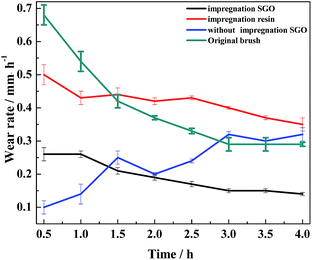
A novel type of resin-based electrical contact material (RECM) was prepared for the first time via the second curing of a sulfonated graphene/waterborne epoxy resin after pore formation. The carrying-current wear behavior of the RECMs was tested on a durability test bed of a HMC-2500 type electric power tool, and microstructural characterization of the RECMs surface was carried out using AFM, SEM, TEM and XPS. The results show that the carrying-current wear rate of the RECMs impregnated with sulfonated graphene was approximately 56% of that of the RECMs not impregnated with sulfonated graphene, and it was also lower than that of the original carbon brush (widely used in the market). Moreover, AFM analysis indicated that the introduction of sulfonated graphene can significantly improve the surface hardness and toughness of RECMs. It was also found that sulfonated graphene could restrain the stress growth in situ in the micro-crack region, which contributes to the formation of a slight “fish scale” friction film on the wear surface during the wear process. Furthermore, it can effectively improve the integrity of the contact surface between the friction pairs and reduce any abnormal wear and resist arc erosion wear. The research results provide guidance and a theoretical basis for the research and design of high performance electrical contact materials.
1. Introduction
Resin-based electrical contact materials (RECMs), with high resistance and large contact voltage drop, are always applied in the commutation of a motor. RECMs, as the core component, maintain normal running of the sliding and rotating electromechanical system and the friction system.1–3 At present, there is a problem that RECMs are not homogeneous and their interfaces are difficult to be coordinated due to their multi-phase, multi-component and porous structures during the service process. As a result, it is difficult to simultaneously acquire wear resistance, anti-arc erosion and high matching characteristics. As the demand and consumption of human transportation and energy constantly increases, upgrading the electromechanical systems of manpower-assisted extension tools has attracted increasing concern in the electrical contact materials field, particularly in the advanced matching between the friction pairs.4In order to handle the defects of existing RECMs, such as poor wear resistance, unstable carrying-current wear performance and serious electrical erosion, researchers have carried out a lot of related work. Hu et al.5 prepared high-resistivity RECMs, using molybdenum disulfide as a lubricant and found that MoS2 could help RECMs to form a stable lubricating film on the surface of the commutator, which can reduce the wear rate of RECMs. Furthermore, Uecker et al.6 introduced ZnCO3 as a lubricant between the friction pairs and found that the addition of ZnCO3 improved the surface performance as well as the wear properties of the composite. In addition, some researchers studied the effects of the working conditions on RECMs. Feng et al.7 found that CO, CO2 and other volatile gases, generated by graphite under the action of arc erosion, exacerbated the wear rate and surface crack propagation of RECMs upon increasing the current intensity. Hu et al.8 discovered the effects of relative humidity on the wear resistance of RECMs and found that under 10% relative humidity (RH), it was difficult to form an oxide lubrication layer and improve the wear resistance properties on the wear surface of RECMs. The research mentioned above has promoted relevant theoretical research on the carrying-current wear of RECMs to a certain extent, but has not fundamentally solved the problems of interface matching and coordination of RECMs as well as clarifying the characteristics of the structural and functional integration or regulatory mechanism of the dynamic friction film on the wear surface.
As a new type of two-dimensional carbon nanomaterial, sulfonated graphene (SGO) belongs to graphene oxide (GO) in which the introduced sulfonic groups have excellent hydrophilicity and physical–chemical properties,9 which lead to excellent strength and electrical properties. Furthermore, the oxygen-containing functional groups on the surface of SGO can be chained with oxygen-containing groups on the surface of the coke material and cross-linking can be achieved, establishing a better matching relationship with the RECMs.10,11 In this study, SGO was used as the interface modifier of RECMs and introduced into the composite pores through the process of second curing after pore formation, achieving a two-step toughening effect in the composite materials, as well as improving the RECMs' mechanical and electrical performance. At the same time, the effects of sulfonated graphene/waterborne epoxy resin on the modification of the RECMs microstructure and wear resistance were investigated. The mechanism of the initiation and expansion of micro-cracks in the SGO composites is discussed, and a new mechanism for SGO for improving the integrity of the friction film between the friction pairs and inhabiting the arc erosion is studied in detail.
2. Experimental
2.1. Materials preparation
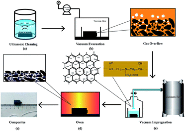
A resin-based electrical contact blank material, with 23 wt% diglycidyl ether of bisphenol A resin (DGEBA) used as the binder phase, 77 wt% artificial graphite powder as the conductive lubricating phase and an appropriate pore-forming agent, was prepared via the processes of kneading, milling, molding and curing. The blank material was impregnated with sulfonated graphene/waterborne epoxy resin (the water solubility was greater than 30%) under a vacuum environment, as is shown in Fig. 1.First, the composite material was ultrasonicated in anhydrous ethanol until no obvious carbon particles were observed and no bubbles escaped, as shown in Fig. 1a. Second, the sulfonated graphene/waterborne epoxy resin (mass ratio 2![[thin space (1/6-em)]](https://www.rsc.org/images/entities/char_2009.gif) :
:![[thin space (1/6-em)]](https://www.rsc.org/images/entities/char_2009.gif) 3) was introduced into the open hole of the blank material via a vacuum impregnation technique, and the impregnation time was 60 min (Fig. 1b and c). Finally, the RECMs were successfully prepared after a secondary curing step of the blank material at 150 °C (Fig. 1d and e).
3) was introduced into the open hole of the blank material via a vacuum impregnation technique, and the impregnation time was 60 min (Fig. 1b and c). Finally, the RECMs were successfully prepared after a secondary curing step of the blank material at 150 °C (Fig. 1d and e).
2.2. Materials characterization
The surface resistivity of the RECMs was measured using a SB100A/21A four probe metal/semiconductor resistivity measuring instrument, and the shore hardness of the RECMs was evaluated using a HS-19A type shore hardness tester. The morphology, mechanical properties and DMT modulus distribution of the different RECMs wear surfaces were characterized using atomic force microscopy (AFM, Bruker, bioscope system). Environmental scanning electron microscopy (SEM, Quanta FEI 200) and high-resolution transmission electron microscopy (TEM, JSM-3010) were employed in the present study to analyze the microstructure of the samples. The carrying-current wear behavior of the RECMs was tested on a durability test bed of a HMC-2500 type electric power tool (the test conditions were at a rated speed of 10![[thin space (1/6-em)]](https://www.rsc.org/images/entities/char_2009.gif) 000 rpm, a load voltage of 235 V, a rated input power 2800 W and size of 7 × 11 × 17 mm3). X-ray photoelectron spectroscopy (XPS, Thermo Fisher, ESCALAB 250Xi) was also performed to analyse the chemical composition of the wear surface of the RECMs. All the abovementioned tests were performed at 20 ± 2 °C and 70–80% relative humidity.
000 rpm, a load voltage of 235 V, a rated input power 2800 W and size of 7 × 11 × 17 mm3). X-ray photoelectron spectroscopy (XPS, Thermo Fisher, ESCALAB 250Xi) was also performed to analyse the chemical composition of the wear surface of the RECMs. All the abovementioned tests were performed at 20 ± 2 °C and 70–80% relative humidity.
3. Results and discussion
3.1. Physical performance analysis
Table 1 shows the main physical properties of the RECMs before and after impregnating sulfonated graphene. It can be seen from the table that the density of the RECMs after the impregnation of SGO did not dramatically change, but the porosity was 7.8%, which is lower than those observed for the non-impregnated SGO (15.4%) and impregnated with resin alone (9%). The table also illustrates that the sulfonated graphene/waterborne resin system was successfully impregnated into the pores of the RECMs, which reflects the good mobility of SGO. The overall content of the SGO introduced was 0.007 g, accounting for 7% of the total mass of the RECMs in this study. The resistivity of the RECMs impregnated with the sulfonated graphene/waterborne resin system was nearly three times higher than that of the non-impregnated samples and half of that of the RECMs impregnated with the resin alone. This is because the main components of the friction film are SGO and waterborne resin, and the SGO's surface contains a large number of sulfonate groups, which hinder the effective transmission of some electrons. Moreover, SGO has a unique two-dimensional and six-membered ring structure, which can form π orbitals and plays a critical role in the transmission of current,12 thereby making the SGO display weak conductivity.| Sample | Sample without SGO | Sample with SGO | Sample with resin |
|---|---|---|---|
| a The porosity was measured by the drainage method. | |||
| Density (g cm−3) | 1.217 | 1.232 | 1.324 |
| Wear surface resistivity (μΩ m) | 160 | 540 | 1170 |
| Porosity | 15.4% | 7.8% | 9% |
| Shore hardness (HSD) | 8 | 10 | 9 |
3.2. AFM analysis of wear surface
The morphology, DMT modulus distribution (based on the Derjaguin–Muller–Toporov model) and surface mechanical properties of the different RECMs are shown in Fig. 2 and 3. The DMT modulus distribution was obtained by randomly drawing a region on the surfaces of the different RECMs, which is shown in Fig. 2a–c. It is clear that the average value of the DMT modulus of the RECMs impregnated with sulfonated graphene/waterborne resin was approximately 20 GPa, which is nearly four times and twice higher than that of the non-impregnated and impregnated resin alone, respectively. In addition, the deformation of sample (c) was significantly less than that of sample (a) and (b), corresponding to the sample surface morphology features shown in Fig. 3. The curve (force–distance curve) (Fig. 3d) of force and probe-sample distance relationship was obtained by randomly choosing a point. It was obvious that the abscissa interval between inflexion and the deepest point (the maximum point of force corresponding to the y-coordinate axis) of the pressed part (Fig. 3d(a–c)) was the sample deformation, which was the largest amount of sample that was pressed in the process. Apparently, the deformation of sample (c) was significantly smaller than sample (a) and (b). These results illustrate that the introduction of sulfonated graphene/waterborne resin can not only improve the integrity of the microstructure, but also increase the hardness and toughness of the RECMs surface, which can contribute to the inhibition of stress growth in situ in the micro-crack region and the realization of structure-function integration in RECMs. Consistent with these findings, the wear resistance of the RECMs was enhanced through the introduction of sulfonated graphene (Fig. 4). | ||
| Fig. 2 AFM images of the DMT modulus distribution for the different RECMs: (a) without SGO, (b) only the resin and (c) impregnated sulfonated graphene/resin, (d) The DMT modulus. | ||
3.3. Analysis of friction and wear performance under current
In the process of carrying-current in the RECMs, the wear performance is the most important criterion for measuring the performance of the materials.13 In this study, the carrying-current performance of the different RECMs was tested under the same conditions (a maximum load voltage of 235 V, a maximum load of 35 N and a maximum power of 1450 W). Fig. 4 shows the carrying-current wear rate of the different RECMs after 4 h of wear. We find that only the current-carrying wear rate of the RECMs with impregnated SGO does not significantly fluctuate and is also much lower than those of all the other samples (Fig. 4). During the initial stage of carrying-current wear, the wear rate of the impregnated sample was 0.26 mm h−1, which then gradually decreased to 0.14 mm h−1 and remained at a stable value. The non-impregnated sample had a low wear rate because the carbon material formed an oxide film at the beginning of the wear process.8 The oxide film became ineffective with increasing wear time and temperature. The SGO with better film forming properties can be distributed evenly into the contact spot area of the friction pairs in the process of carrying-current wear. That is to say, as the degree of adhesion of the friction pairs increases, the friction point of contact of the current conduction can effectively improve. At the same time, the artificial graphite debris was coated with the acidic functional groups of SGO under the action of frictional heat and electric erosion, which effectively collects and adsorbs fine debris, result in improving the integrity of the friction film, significantly reducing the abnormal wear of the wear surface, and inhibiting arc erosion and heat accumulation.Fig. 5 shows the micromorphology of the wear surface of the different RECMs. According to Fig. 5a, there are gullies on the surface of the RECMs without impregnated SGO, which decreases the number of contact points on the wear surface, resulting in heat accumulation and intensified wear. In contrast, it can be seen that the surface of the RECMs with impregnated SGO is relatively smooth and there are no obvious arc erosion pits. Moreover, the grinding crack area is more smooth and there are no obvious ablation pits and oxidation erosion pits.14 The friction film on the surface of the RECMs presents a “fish scale” structure (A, B, C areas in Fig. 5d).15 Such type of two-dimensional flake wear, instead of three-dimensional particle abrasion, is more helpful to inhibit the formation of corrosive pits on the carbon net surface and helps the wear surface to transmit electrons, dissipate heat and replace the original granular wear. The phenomenon that the surface resistivity of the material increases due to the introduction of the resin was coordinated by the friction film, which also inhibits the mechanical wear and electrical erosion of the wear surface. The filling and cross-linking actions of SGO not only increase the bonding of the composite phases as a “bridge”, but also restrain the growth of micro-cracks and improve the wear resistance of RECMs. This indicates that few-layer SGO contributes to the formation of different levels of friction film and participates in the wear process. It is also involved in assisting the next round of friction film formation.16,17 Therefore, the integrity of the friction film between the friction pairs was improved and the abnormal wear of the wear surface was significantly reduced, which presents a similar agreement with the Canadian Bennewitz's conclusion that adding graphene to SiC can reduce its friction co-efficient.18
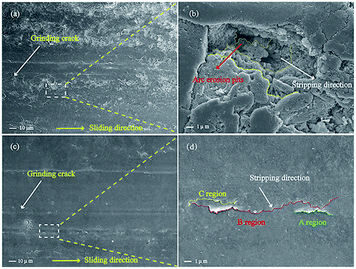 | ||
| Fig. 5 (a) and (c) SEM images of the wear surface of the RECMs before and after impregnation with SGO/resin, respectively. (b) and (d) Partial magnification images. | ||
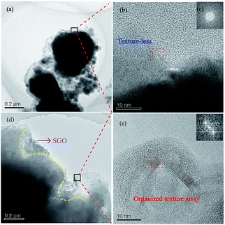
It was observed that the wear debris of the material without the impregnation of SGO was dispersedly distributed in small flakes and was looser, as shown in Fig. 6a. At the same time, the texture of the edge of the wear debris was disordered, showing an amorphous structure during the carrying-current wear process (Fig. 6b and c). The microstructure of the wear surface will be a more disordered arrangement under the actions of arc erosion and oxidation. Therefore, the wear debris can easily fall off in the process of wear, resulting in a high wear rate and high sparks, which is consistent with Fig. 5. While the wear debris of the RECMs with SGO exhibits a complete flake distribution, the SGO is distributed in the edge of the flakes and forms a good lap state, which indicates that the artificial graphite under the action of SGO tends to stack together. Moreover, SGO has great surface energy and can exert a “self-repairing effect” on the artificial graphite powder after heating.9 The wear debris of the RECMs with the involvement of SGO showed an organized textured array according to the HRTEM and FFT images, as shown in Fig. 6e and f, which can help to adjust the wear surface to form the “fish scale” friction film used for anti-oxidation and anti-arc erosion. Such properties make it possible to prevent the high temperature pulverization and peeling splash of the artificial graphite during the process of carrying-current wear and this is why the RECMs have good wear performance. These results are consistent with the phenomenon of the “fish scale” progressive wear of the friction film presented in Fig. 5b.
3.4. XPS analysis of wear surface
In order to investigate the action mechanism of SGO during the carrying-current wear process, the chemical composition on the wear surface of the RECMs was analysed using XPS. Fig. 7 shows the elemental binding energy spectra of the RECMs wear surface before and after the impregnation of sulfonated graphene. The elemental content of the different RECMs wear surface is given in Table 2. It can be seen in Fig. 7 that there is a sharp peak at a binding energy of 932.2 eV, which is the characteristic peak of cuprous oxide.19,20 Clearly, this confirms that the main component (in addition to carbon) of the friction film was cuprous oxide in the proposed process of wear.21–23 The C/O and C/Cu contents in the RECMs without SGO are significantly lower than those of the RECMs with SGO (Table 2). This indicates that the RECMs without SGO suffers severe oxidized corrosion and exfoliation wear during the carrying-current wear process. The introduction of SGO into the pores of the RECMs contributed to the formation of the “fish scale” friction film and accordingly, the serious oxidized corrosion and exfoliation wear on the wear surface of the RECMs were restrained efficiently.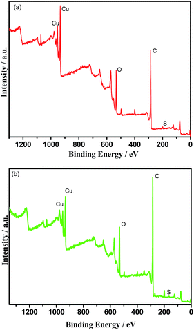 | ||
| Fig. 7 The elemental binding energy spectra of the RECMs wear surface (a) with the impregnation of SGO and (b) without the impregnation of SGO. | ||
| Sample | C (%) | O (%) | Cu (%) | S (%) |
|---|---|---|---|---|
| Without the impregnation of SGO | 71.58 | 16.46 | 7.86 | 0.33 |
| With the impregnation of SGO | 77.87 | 14.17 | 5.07 | 0.82 |
3.5. Wear mechanism
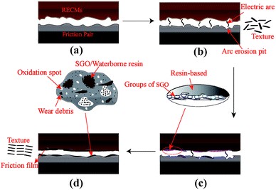
The wear mechanism of the RECMs impregnated sulfonated graphene/waterborne resin focuses on the friction film formed by the involvement of SGO and mainly involves the mechanism of restraining electrical erosion wear, as shown in Fig. 8. This is because the wear surface is rough and the friction film is not yet formed in the initial stage of the carrying-current wear process, and this can easily lead to mechanical wear and electrical erosion wear and form the arc erosion pits on the surface of RECMs, as shown in Fig. 8a and b. The temperature of the wear surface gradually increases as the carrying-current wear continues, and then SGO gets involved in the wear process, partially filling the arc erosion pits and wear surfaces; thus, the contact area of friction between the friction pairs increases, which achieves the purpose of rapid cooling of the arc between the friction pairs by controlling the occurrence rate of the current in the carrying-current wear circuit (Fig. 8c). At the same time, a continuous composite friction film is gradually formed on the wear surface between the RECMs and copper friction pair, which closes the partially opened holes on the wear surface of the material and effectively prevents the diffusion of oxygen to the sub-surface. Therefore, the wear between the friction pairs achieves a dynamic balance, and the integrity of the friction film is improved by the introduction of the sulfonated graphene/waterborne resin system, as shown in Fig. 8d, achieving the coordination and matching between the internal phases of the RECMs. Moreover, it also plays a crucial role in regulating the stress growth in situ in the micro-crack region and restrains arc erosion, which contributes to realizing the structural and functional integration of RECMs.4. Conclusions
A novel type of RECM was prepared for the first time by the second curing of a sulfonated graphene/waterborne epoxy resin after pore formation. The wear rate of the RECMs impregnated with the sulfonated graphene/waterborne resin is significantly lower than that of the non-impregnated RECMs. Moreover, the RECMs have good resistance to arc erosion and mechanical wear resistance under the conditions of carrying-current wear. Under the conditions of carrying-current wear, SGO gets involved and contributes to the formation of a “fish scale” friction film that restrains the stress growth in situ in the micro-crack region, regulates the microstructure and mechanical properties of the surface layer, and significantly reduces the arc erosion wear of the wear surface.Conflicts of interest
There are no conflicts to declare.Acknowledgements
The authors gratefully acknowledge the financial support for this work provided by the National Natural Science Foundation of China (Grants No. 51772081) and the Natural Science Foundation of Hunan Province (Grants Nos. 2016JJ2024 and 2016JJ2025).Notes and references
- J. K. Lancaster and I. W. Stanley, Br. J. Appl. Phys., 2002, 15, 29–41 CrossRef.
- J. T. Xia, Z. L. Hu, Z. H. Chen and G. Y. Ding, Trans. Nonferrous Met. Soc. China, 2007, 17, 1379–1384 CrossRef CAS.
- T. Ding, G. X. Chen, X. Wang, M. H. Zhu, W. H. Zhang and W. X. Zhou, Tribol. Int., 2010, 166, 1–6 Search PubMed.
- D. F. Zeng, L. T. Lu, Y. B. Zhang, J. W. Zhang, Z. F. Wen and M. H. Zhu, J. Tribol., 2012, 6, 599–605 Search PubMed.
- Z. L. Hu, Z. H. Chen, J. T. Xia and G. Y. Ding, Trans. Nonferrous Met. Soc. China, 2008, 18, 340–345 CrossRef.
- A. Uecker, Wear, 2003, 255, 1286–1290 CrossRef CAS.
- Y. Feng, M. Zhang and Y. Xu, Carbon, 2005, 43, 2685–2692 CrossRef.
- Z. L. Hu, Z. H. Chen and J. T. Xia, Wear, 2008, 264, 11–17 CrossRef CAS.
- X. L. Fu, Y. Wang, Y. Z. Pan and X. Y. Wang, J. Wuhan Univ. Technol., Mater. Sci. Ed., 2017, 2, 272–277 CrossRef.
- N. Oger, Y. F. Lin, C. Labrugère, E. L. Grognec, F. Rataboul and F.-X. Felpin, Carbon, 2016, 96, 342–350 CrossRef CAS.
- F. Liu, J. Sun, L. F. Zhu, X. J. Meng, C. Z. Qi and F. S. Xiao, J. Mater. Chem., 2012, 22, 5495–5502 RSC.
- C. Chen, S. H. Qiu, M. J. Cui, S. L. Qin, G. P. Yan, H. C. Zhao, L. P. Wang and Q. J. Xue, Carbon, 2017, 114, 362–366 Search PubMed.
- P. Wang, H. B. Zhang, J. Yin, X. Xiong, C. Tan, C. Y. Deng and Z. Q. Yan, Wear, 2017, 380–381, 59–65 CrossRef CAS.
- X. Z. Xiong, C. J. Tu, D. Chen, J. Q. Zhang and J. H. Chen, Tribol. Lett., 2014, 53, 293–301 CrossRef.
- X. M. Li, T. T. Yang, Y. Yang, J. Zhu, L. Li, F. E. Alam, X. Li, K. L. Wang, H. Y. Cheng, C. T. Lin, Y. Fang and H. W. Zhu, Adv. Funct. Mater., 2016, 26, 1323–1324 Search PubMed.
- M. G. Jacko, P. H. S. Tsang and S. K. Rhee, Wear, 1989, 133, 23–38 CrossRef CAS.
- J. D. Wei and H. Chen, Mater. Sci. Forum, 2014, 788, 621–626 CrossRef.
- T. Filleter, J. L. Mcchesney, A. Bostwick, E. Rotenberg, K. V. Emtsev, Th. Seyller, K. Horn and R. Bennewitz, Phys. Rev. Lett., 2009, 102, 1–4 CrossRef PubMed.
- W. W. Shen, D. S. Mao, Z. M. Luo and J. Yu, RSC Adv., 2017, 7, 27689–27698 RSC.
- Z. M. Luo, D. S. Mao, W. W. Shen, Y. L. Zheng and J. Yu, RSC Adv., 2017, 7, 9732–9743 RSC.
- T. Ding, G. X. Chen, J. Bu and W. H. Zhang, Wear, 2011, 271, 1629–1636 CrossRef CAS.
- W. J. Spry and P. M. Scherer, Wear, 1961, 4, 137–149 CrossRef.
- Z. L. Hu, J. T. Xia, Z. H. Chen, G. Y. Ding, R. X. Ning and X. Q. Wu, Carbon, 2007, 3, 8–10 Search PubMed.
| This journal is © The Royal Society of Chemistry 2017 |

