 Open Access Article
Enhancing the performance and stability of carbon-based perovskite solar cells by the cold isostatic pressing method†
Yangwen Zhanga,
Jize Wanga,
Xue Liua,
Wangnan Lib,
Fuzhi Huanga,
Yong Penga,
Jie Zhong a,
Yibing Cheng
 ac and
Zhiliang Ku
 *a
*a
aState Key Laboratory of Advanced Technologies for Materials Synthesis and Processing, International School of Materials Science and Engineering, Wuhan University of Technology, 122 Luoshi Road, Wuhan, Hubei, P. R. China. E-mail: zhiliang.ku@whut.edu.cn
bHubei Key Laboratory of Low Dimensional Optoelectronic Material and Devices, Hubei University of Arts and Science, 296 Longzhong Road, Xiangyang, Hubei Province, P. R. China
cDepartment of Materials Science and Engineering, Monash University, Wellington Road, Clayton, VIC 3800, Australia
First published on 17th October 2017
Abstract
The cold isostatic pressing method was used as a post-treatment process for enhancing the power conversion efficiency and stability of carbon-based perovskite solar cells without hole transport materials.
In the past few years, organic–inorganic hybrid lead halide perovskite solar cells (PSCs) have demonstrated enormous potential for next generation photovoltaics because of their ease and low cost of fabrication in combination with high power conversion efficiency (PCE). In fact, solar cells employing solution-processed hybrid perovskite materials as light absorbers have surpassed 22% PCE,1 which is on a par with the most mature photovoltaic (PV) technologies (multi-crystalline Si, 21.3%). Nevertheless, PSCs still need to surmount challenges to their stability, low cost, reproducibility and industrial scaling-up before they can enter the pantheon of breakthrough commercial PV technologies. Therefore, several strategies2–10 have been developed by integrating these solution-processed perovskite compounds to address the aforementioned issues. Among these strategies, carbon-based PSCs have received wide attention by many research groups11–16 since the first report in 2013.10 In comparison to other types of PSCs, carbon-based PSCs without hole-transport materials (HTM) take full advantage of the superior properties of perovskite-type absorbers such as long charge carrier diffusion length and high mobility.17–19 In this case, the non-use of HTM can save the material expense, simplify the fabrication procedures and enhance the stability of PSCs. More importantly, carbon-based PSCs without HTM can be fabricated by full-printing process, which would be of great benefit to scale up the solar devices for commercial applications. However, like anything else, the carbon electrodes have their shortcomings such as low-conductivity and loose porous structure. Typically, the thickness of carbon electrode was controlled at about 10 μm to ensure conductivity and properly filtration of perovskite precursor. Hence, high cell resistance along with uncontrolled crystallization of the perovskite precursor solution in carbon-based PSCs are the limiting factors for their further development.10,20 At this point, some specific and innovative strategies must be employed to address the above problem.
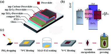
Based on our previous experience,21,22 cold isostatic pressing (CIP) can be used to compress the mesoporous TiO2 beads to obtain good connection between the beads. Since the carbon-based PSCs have similar mesoporous structure to the TiO2 beads, we believe that CIP could have positive effect on reducing the overall resistance of the cell. In this work, we employed CIP as a post treatment for carbon-based PSCs. The results showed that this CIP treatment can not only enhance the compactness of the porous layers, but also provides a pathway to fabricate high performance carbon-based PSCs with high humidity resistance. The carbon-based PSCs were fabricated by the procedures reported previously.23 Briefly, TiO2 compact layer was firstly deposited on FTO substrate by aerosol spray pyrolysis method. Then, TiO2, ZrO2 and carbon mesoporous films were successively deposited on the TiO2 compact layer (see Fig. 1a). Afterwards, FAxMA1−xPbI3 perovskite was loaded by immersing the as-prepared films filled with PbI2 in FAI/MAI (0.79![[thin space (1/6-em)]](https://www.rsc.org/images/entities/char_2009.gif) :
:![[thin space (1/6-em)]](https://www.rsc.org/images/entities/char_2009.gif) 0.21 in mole ratio) 2-propanol solution, known as “two-step” method.24 Finally, the prepared devices were encapsulated in vacuum, followed by cold isostatic pressing under different pressure (Fig. 1c, see ESI for more details†). In these devices, both MAPbI3 and FAPbI3 perovskite can harvest light and generate photoelectrons, which could be collected by mesoporous TiO2 layer. Meanwhile, the corresponding holes at their valence band were collected by carbon counter electrode, forming photocurrent (energy level diagram is presented in Fig. 1b).
0.21 in mole ratio) 2-propanol solution, known as “two-step” method.24 Finally, the prepared devices were encapsulated in vacuum, followed by cold isostatic pressing under different pressure (Fig. 1c, see ESI for more details†). In these devices, both MAPbI3 and FAPbI3 perovskite can harvest light and generate photoelectrons, which could be collected by mesoporous TiO2 layer. Meanwhile, the corresponding holes at their valence band were collected by carbon counter electrode, forming photocurrent (energy level diagram is presented in Fig. 1b).
XRD measurement was used to identify the FAxMA1−xPbI3 perovskite in the device. As shown in Fig. 2, the XRD pattern of the blank TiO2/ZrO2/carbon film has a strong peak at 26.3°, which should be indexed to (002) reflection of graphite. After the loading of PbI2, new peaks emerged at 12.6°, 25.9°, 34.2° and 39.7°, corresponding to the characteristic peaks of PbI2. By immersing in FAI/MAI solution, nearly all the PbI2 converted to FAxMA1−xPbI3 perovskite. The peaks emerging at 14°, 28° and 31.4° are similar with that of tetragonal MAPbI3, indicating FAxMA1−xPbI3 with trigonal symmetry (P3m1) has been synthesised (green line). Note that, no obvious σ-FAPbI3 (yellow phase) peaks can be find in the spectra of the FAxMA1−xPbI3 based cell, attributing to the stabilizing effect from MAI.25
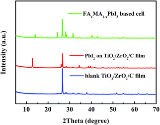 | ||
| Fig. 2 The XRD spectra of the blank TiO2/ZrO2/carbon film and PbI2 in the TiO2/ZrO2/carbon film, and the FAxMA1−xPbI3 based cell. | ||
Interestingly, seen from the front side, all of the active area became darker after the treatment of CIP (inset, Fig. 3). The microstructure of these devices was characterized by scanning electron microscopy (SEM) from cross section. Before CIP treatment, we can clearly see the carbon layer, composed of flaky graphite and small carbon black particles, shows loose and porous morphology with the thickness of 10 μm (Fig. 3a). However, after CIP treatment, all of the three layers were compressed and it's hard for us to identify the boundaries (Fig. 3a). This will help the holes transfer from perovskite to carbon and as a result, reduce the overall cell resistance (Rcell).
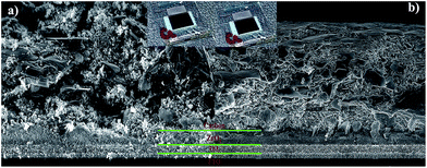 | ||
| Fig. 3 SEM images from the cross section and optical photographs (inset) of the FAxMA1−xPbI3 based cells (a) before and (b) after CIP treatment. | ||
To confirm this, the photovoltaic performance of the devices (4 groups, each group consist of 8 cells chosen randomly from 32 cells) treated by CIP method with different pressures (0 MPa, 75 MPa, 150 MPa and 225 MPa) was characterized. As summarized in Fig. 4, without treatment (0 MPa), the first group of cells exhibit an average short-circuit current density (avg-Jsc) of 19.1 mA cm−2, open-circuit voltage (avg-Voc) of 879 mV and average fill factor (avg-FF) of 0.53, yielding average power conversion efficiency (avg-PCE) of 9.01%. The second (75 MPa) and third (150 MPa) group of cells have similar avg-Jsc with that of the first group and have a slight improvement in avg-Voc. However, the avg-FF of the devices grew significantly as the increase of pressure, indicating better charge transfer in mesoporous films. The last group of cells treated by CIP at 225 MPa possess the worst photovoltaic parameters, which should ascribe the damage of device at excessively high pressure. Taken together, the device treated by CIP at 150 MPa (marked as CIP150) have best performance (avg-PCE = 11.1%).
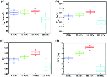 | ||
| Fig. 4 Photovoltaic parameters of 4 groups of cells (each group include 8 cells) treated by CIP with different pressures. | ||
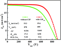
J–V curves of the champion cell before and after the CIP150 treatment are shown in Fig. 5. After CIP150 procedure, the value of Rcell determined by the slope of the curve dropped from 17.2 Ω to 8.9 Ω, rendering higher FF. PCE of the cell increased from 9.10% to 11.6%, with growth of 27%.
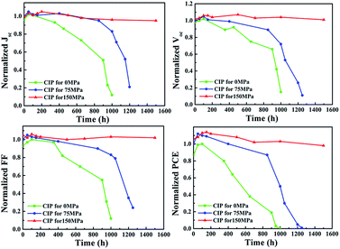
Long-term stability of the cells without encapsulation was tested at 25 °C and 50% relative humidity (Fig. 6). After 1000 h, the cell without CIP treatment almost lost all of its performance. However, the cell treated by CIP75 maintained 85% of its initial PCE after 1000 h, but decayed quickly in the next 200 h. Surprisingly, the performance parameters of the cell treated by CIP150 have no obvious degradation even after 1500 h.
The good stability of the CIP-treated cells in humidity should attribute to the compact surface of the cell. To confirm this, contact-angle measurements were conducted on the carbon layer on top of the cells (see Fig. 7). Without CIP treatment, the carbon layer filled with perovskite showed a contact angle of 60° to water. However, by using CIP treatment, the value of contact angle goes up with increasing pressure. As we can imagine, with more compact structure and larger contact angle to water, the carbon/perovskite layer on top of cell will offers better protection against moisture, and eventually, improves stability.
 | ||
| Fig. 7 Optical images of contact-angle measurement for the PSC device treated by CIP with different pressures. | ||
Conclusions
In sum, cold isostatic pressing (CIP) method was used for enhancing the performance of hole-conductor-free perovskite solar cells with a triple-layer structure (TiO2/ZrO2/carbon). After CIP process, the mesoporous films filling with perovskite absorber were pinched by the pressure and thus have high compactness. Hence, the charge transport resistance of the solar device can be reduced and moisture can also be blocked by the compact carbon layer. As a result, the champion solar cell enhanced its efficiency from 9.10% to 11.6% via CIP process and showed superior stability (1500 h) in 50% relative humidity circumstance.Conflicts of interest
There are no conflict to declare.Acknowledgements
The authors acknowledge the financial support by National Natural Science Foundation of China (NSFC 51402115, 51672202, 51702243), Hubei Provincial Natural Science Foundation of China (2016CFB464), The Technological Innovation Key Project of Hubei Province (2016AAA041), The Fundamental Research Funds for the Central Universities (WUT: 2016IVA093, 2016IVA089, 2016IVA 085, 2016III030, 2017III022) and Hubei Key Laboratory of Low Dimensional Optoelectronic Material and Devices (HLOM151001).Notes and references
- N. R. E. L. N. Best Research Cell_Efficiencies, April 14 2017, https://www.nrel.gov/pv/assets/images/efficiency-chart.png.
- T. Leijtens, G. E. Eperon, S. Pathak, A. Abate, M. M. Lee and H. J. Snaith, Nat. Commun., 2013, 4, 2885 CrossRef PubMed.
- Q. Tai, P. You, H. Sang, Z. Liu, C. Hu, H. L. W. Chan and F. Yan, Nat. Commun., 2016, 7, 11105 CrossRef CAS PubMed.
- F. Bella, G. Griffini, J.-P. Correa-Baena, G. Saracco, M. Grätzel, A. Hagfeldt, S. Turri and C. Gerbaldi, Science, 2016 DOI:10.1126/science.aah4046.
- H. Tan, A. Jain, O. Voznyy, X. Lan, F. P. García de Arquer, J. Z. Fan, R. Quintero-Bermudez, M. Yuan, B. Zhang, Y. Zhao, F. Fan, P. Li, L. N. Quan, Y. Zhao, Z.-H. Lu, Z. Yang, S. Hoogland and E. H. Sargent, Science, 2017 DOI:10.1126/science.aai9081.
- K. A. Bush, A. F. Palmstrom, Z. J. Yu, M. Boccard, R. Cheacharoen, J. P. Mailoa, D. P. McMeekin, R. L. Z. Hoye, C. D. Bailie, T. Leijtens, I. M. Peters, M. C. Minichetti, N. Rolston, R. Prasanna, S. Sofia, D. Harwood, W. Ma, F. Moghadam, H. J. Snaith, T. Buonassisi, Z. C. Holman, S. F. Bent and M. D. McGehee, Nat. Energy, 2017, 2, 17009 CrossRef CAS.
- A. Mei, X. Li, L. Liu, Z. Ku, T. Liu, Y. Rong, M. Xu, M. Hu, J. Chen, Y. Yang, M. Gratzel and H. Han, Science, 2014, 345, 295–298 CrossRef CAS PubMed.
- M. Yang, Z. Li, M. O. Reese, O. G. Reid, D. H. Kim, S. Siol, T. R. Klein, Y. Yan, J. J. Berry, M. F. A. M. van Hest and K. Zhu, Nat. Energy, 2017, 2, 17038 CrossRef CAS.
- Y. Wu, X. Yang, W. Chen, Y. Yue, M. Cai, F. Xie, E. Bi, A. Islam and L. Han, Nat. Energy, 2016, 1, 16148 CrossRef CAS.
- Z. Ku, Y. Rong, M. Xu, T. Liu and H. Han, Sci. Rep., 2013, 3, 3132 CrossRef PubMed.
- T. A. N. Peiris, A. K. Baranwal, H. Kanda, S. Fukumoto, S. Kanaya, L. Cojocaru, T. Bessho, T. Miyasaka, H. Segawa and S. Ito, Nanoscale, 2017, 9, 5475–5482 RSC.
- X. Zheng, H. Chen, Q. Li, Y. Yang, Z. Wei, Y. Bai, Y. Qiu, D. Zhou, K. S. Wong and S. Yang, Nano Lett., 2017, 17, 2496–2505 CrossRef CAS PubMed.
- S. Liu, K. Cao, H. Li, J. Song, J. Han, Y. Shen and M. Wang, Sol. Energy, 2017, 144, 158–165 CrossRef CAS.
- N. Cheng, P. Liu, F. Qi, Y. Xiao, W. Yu, Z. Yu, W. Liu, S.-S. Guo and X.-Z. Zhao, J. Power Sources, 2016, 332, 24–29 CrossRef CAS.
- J. Liang, C. Wang, Y. Wang, Z. Xu, Z. Lu, Y. Ma, H. Zhu, Y. Hu, C. Xiao, X. Yi, G. Zhu, H. Lv, L. Ma, T. Chen, Z. Tie, Z. Jin and J. Liu, J. Am. Chem. Soc., 2016, 138, 15829–15832 CrossRef CAS PubMed.
- G. Grancini, C. Roldán-Carmona, I. Zimmermann, E. Mosconi, X. Lee, D. Martineau, S. Narbey, F. Oswald, F. De Angelis, M. Graetzel and M. K. Nazeeruddin, Nat. Commun., 2017, 8, 15684 CrossRef CAS PubMed.
- D. Shi, V. Adinolfi, R. Comin, M. Yuan, E. Alarousu, A. Buin, Y. Chen, S. Hoogland, A. Rothenberger, K. Katsiev, Y. Losovyj, X. Zhang, P. A. Dowben, O. F. Mohammed, E. H. Sargent and O. M. Bakr, Science, 2015, 347, 519–522 CrossRef CAS PubMed.
- S. D. Stranks, G. E. Eperon, G. Grancini, C. Menelaou, M. J. Alcocer, T. Leijtens, L. M. Herz, A. Petrozza and H. J. Snaith, Science, 2013, 342, 341–344 CrossRef CAS PubMed.
- G. Xing, N. Mathews, S. Sun, S. S. Lim, Y. M. Lam, M. Gratzel, S. Mhaisalkar and T. C. Sum, Science, 2013, 342, 344–347 CrossRef CAS PubMed.
- S. G. Hashmi, D. Martineau, M. I. Dar, T. T. T. Myllymaki, T. Sarikka, V. Ulla, S. M. Zakeeruddin and M. Gratzel, J. Mater. Chem. A, 2017 10.1039/c7ta04132b.
- F. Huang, D. Chen, Y. Chen, R. A. Caruso and Y.-B. Cheng, J. Mater. Chem. C, 2014, 2, 1284–1289 RSC.
- H. C. Weerasinghe, P. M. Sirimanne, G. P. Simon and Y.-B. Cheng, Prog. Photovoltaics Res. Appl., 2012, 20, 321–332 CrossRef CAS.
- M. Hu, L. Liu, A. Mei, Y. Yang, T. Liu and H. Han, J. Mater. Chem. A, 2014, 2, 17115–17121 CAS.
- J. Burschka, N. Pellet, S. J. Moon, R. Humphry-Baker, P. Gao, M. K. Nazeeruddin and M. Gratzel, Nature, 2013, 499, 316–319 CrossRef CAS PubMed.
- A. Binek, F. C. Hanusch, P. Docampo and T. Bein, J. Phys. Chem. Lett., 2015, 6, 1249–1253 CrossRef CAS PubMed.
Footnote |
| † Electronic supplementary information (ESI) available: Experimental details, IPCE of the champion device. See DOI: 10.1039/c7ra07579k |
| This journal is © The Royal Society of Chemistry 2017 |

