 Open Access Article
Creative Commons Attribution 3.0 Unported Licence
Integrated heart/cancer on a chip to reproduce the side effects of anti-cancer drugs in vitro†
Ken-ichiro Kamei *a,
Yoshiki Katob,
Yoshikazu Hirai*ab,
Shinji Itoc,
Junko Satohc,
Atsuko Okac,
Toshiyuki Tsuchiya
 b,
Yong Chenad and
Osamu Tabatab
aInstitute for Integrated Cell-Material Sciences (WPI-iCeMS), Kyoto University, Yoshida-Ushinomiya-cho, Sakyo-ku, Kyoto 606-8501, Japan. E-mail: kkamei@icems.kyoto-u.ac.jp
bDepartment of Micro Engineering, Kyoto University, Kyotodaigaku-Katsura, Nishikyo-ku, Kyoto 616-8540, Japan. E-mail: hirai@me.kyoto-u.ac.jp
cMedical Research Support Center, Graduate School of Medicine, Kyoto University, Yoshida Konoe-cho, Sakyo-ku, Kyoto 606-8501, Japan
dÉcole Normale Supérieure-PSL Research University, Département de Chimie, Sorbonne Universités, UPMC Univ Paris 06, CNRS UMR 8640 PASTEUR, 24 rue Lhomond, 75005 Paris, France
First published on 24th July 2017
Abstract
Pre-clinical animal tests are used to assess drug efficacy and safety, but are limited by factors such as their suitability as a model for humans, robustness, cost, and ethical issues. While an organ-on-a-chip using human cells is promising for recapitulating human physiological conditions, it is highly desirable in investigations of the side effects of drugs to integrate more than one type of tissue using a designed circulatory system. We have developed a microfluidic device—an Integrated Heart/Cancer on a Chip (iHCC)—using human healthy heart cells (hCMs) and liver cancer cells (HepG2) to recapitulate the side effects of an anti-cancer drug, doxorubicin (DXR), to achieve individual cultures of cells from different tissues on a single device with three sets of artificial blood circulation loops, microfabrication technology for micro valves and a pump provides accurate fluid operation. Using improved soft lithography adopting numerical optimization simulation, the microfluidic device was fabricated with on-chip integration of pneumatic valves and a peristaltic micropump establishing precision fluid flow. The iHCC developed allows modelling of the side effects of DXR on heart cells caused by the production of toxic metabolites (doxorubicinol; DXRol) by HepG2 cells and the delivery of DXRol to heart cells via the circulation loop. Our findings open the door towards the development of a “Body-on-a-Chip.”
Introduction
Drug discovery is now facing issues such as high development costs (over $10 billion US per drug) and long development times (more than 10 years), as well as serious side effects occurring during clinical trials or after introduction into the market.1 These problems are largely attributable to the current improper approach to pre-clinical tests. For example, testing in animals, such as rodents and non-human primates, might yield misleading results because the response of these animals to drug candidates is different from that of humans. In addition, the use of animals for drug discovery has become restricted in many countries due to ethical issues.2 Therefore, pharmaceutical companies take high risks in developing each new drug, and new approaches for drug discovery are desired.To address these issues, the “Organ on a Chip (OoC)”3–11 or “Body on a Chip (BoC)”12–19 technologies, which can mimic human physiological conditions in a microfluidic device, hold great promise as the next generation of pre-clinical tests. Indeed, OoC and BoC were considered as being the “Top 10 Emerging Technologies of 2016” by the World Economic Forum's Meta-Council on Emerging Technologies. In particular, BoC technology allows the establishment of in vitro pre-clinical drug tests capable of assessing absorption, distribution, metabolism, and excretion processes (ADME) for pharmaceutical compounds, all of which profoundly influence the performance and pharmacological activity of a compound. Because BoC consists of multiple tissues in a single device, it also allows observation of the interaction between different tissues.
However, the current BoC platforms have several issues that need to be solved prior to their realization. Most BoC platforms have either a one-way flow stream or a few branches on a chip, so they cannot completely mimic the blood circulation system, or perform ADME tests for periods of days or weeks. Although Maschmeyer et al. reported a four-organ-chip enabling co-culture of human intestine, liver, skin, and kidney cells with a medium circulation loop,20,21 it has not been using for drug testing, and is still at the initial stage. Some studies have achieved medium circulation using an external rotary peristaltic pump, but this requires a large amount of culture medium, and drugs and metabolites might be lost to the tubing.22,23 To the best of our knowledge, current devices have either a closed circulation loop to interconnect tissues or multiplexed capability within a single device. It is important to note that most of the aforementioned OoC or BoC systems have only a single set of experimental conditions in a chip, and do not allow side-by-side comparisons within a device. Furthermore, the direct integration of micropumps in the device often causes difficulties in processing, such as incompatibility and reproducibility, because the existing fabrication methods24–28 are not simple and reliable. Therefore, it is important to develop new microfabrication technologies capable of integrating pumps into a device to minimize the volume of the tested medium and prevent sample loss.
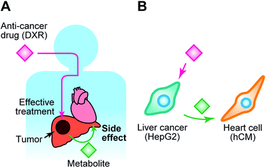
Here, we introduce a BoC, which we have named the Integrated Heart/Cancer on a Chip (iHCC), which offers (1) culture of cells of different tissues within a single device, (2) an artificial blood circulatory system in the form of a closed circulation loop without the use of an external pump, and (3) three sets of loops that can be used to apply different conditions. By using this iHCC, we provide proof of principle for recapitulation of the side effects and cardiotoxicity of an anti-cancer drug in vitro (Fig. 1). The cardiotoxicity induced by anti-cancer drugs29 is a major and serious concern in drug discovery, and the drug metabolites generated from cancerous tissues might exert such side effects on normal tissues via the blood circulatory system (Fig. 1A). In this study, doxorubicin (DXR)30 was selected (Fig. 1B) as a model anti-cancer drug. DXR was originally obtained from Streptomyces peucetius var. caesius, acts through DNA intercalation, and has been used for treating a variety of tumors, such as those of the lung, bladder, liver, breast, and prostate.31 DXR exerts serious side effects on the heart, such as cardiomyopathy caused by undesired apoptosis.32 The use of this combination of cells enables modelling of damage to the heart caused by both the anti-cancer drug and its metabolite produced in cancer cells. In this study, we attempted to reproduce the side effects of DXR using human primary cardiomyocytes (hCMs) from a healthy donor and human hepatocellular carcinoma HepG2 cells, which have been widely used as a cancer cell model for the screening of anti-cancer drugs (Fig. 1B).22,23
Experimental
Materials and methods
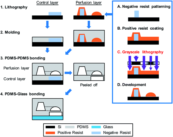 | ||
| Fig. 3 Fabrication of the integrated Heart/Cancer on a Chip (iHCC) microfluidic device. The device was fabricated as follows: (1) for the control layer, the negative resist was patterned on a Si wafer and was used as a casting mold. A casting mold of the perfusion layer was fabricated by a combination of the negative resist patterning and grayscale lithography using positive resist coating. Following this, digital micromirror device (DMD)-based grayscale lithography (DL-1000GS/KCH, NanoSystems Solutions) combined with the simulation-based fabrication approach was employed as described in the previous reports.38,39 (2) The PDMS pre-polymer was poured onto the mold structure and cured. (3) The perfusion layer was bonded onto the control layer. (4) The assembled structure containing the perfusion and control layers was bonded onto a glass substrate using oxygen plasma treatment. | ||
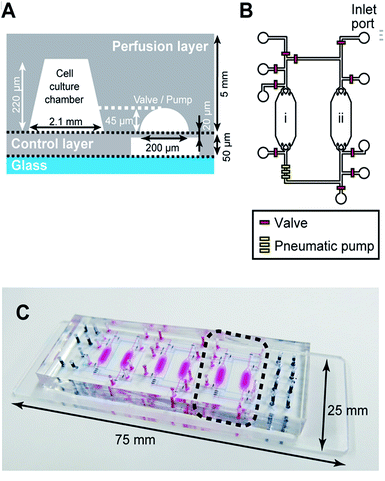
For the pneumatic portion, DMD-based grayscale lithography using numerical optimization38,39 was employed for wafer-level fabrication (Fig. 3).
After fabrication of the resist molds, the PDMS base and curing agents (1![[thin space (1/6-em)]](https://www.rsc.org/images/entities/char_2009.gif) :
:![[thin space (1/6-em)]](https://www.rsc.org/images/entities/char_2009.gif) 10 with a weight ratio, curing agent
10 with a weight ratio, curing agent![[thin space (1/6-em)]](https://www.rsc.org/images/entities/char_2009.gif) :
:![[thin space (1/6-em)]](https://www.rsc.org/images/entities/char_2009.gif) base) were mixed well, degassed in a vacuum desiccator, and poured on the mold structures for the perfusion layer. After curing in a convection oven at 80 °C, the perfusion layer was released from the resist mold. Similarly, for the PDMS layer (thickness, 20 μm), the PDMS membrane was fabricated with the control layer by spin-coating the PDMS pre-polymer onto a resist mold. After spin-coating, the control layer was cured at 80 °C. The two cured PDMS layers were aligned under a microscope and bonded onto the control layer using the partial PDMS curing method,40,41 allowing for the spontaneous adhesive interaction between the two PDMS layers. Finally, the assembled device was permanently bonded using O2 plasma surface treatment (FA-1, SAMCO) onto a microscopic glass slide (25 mm × 75 mm).
base) were mixed well, degassed in a vacuum desiccator, and poured on the mold structures for the perfusion layer. After curing in a convection oven at 80 °C, the perfusion layer was released from the resist mold. Similarly, for the PDMS layer (thickness, 20 μm), the PDMS membrane was fabricated with the control layer by spin-coating the PDMS pre-polymer onto a resist mold. After spin-coating, the control layer was cured at 80 °C. The two cured PDMS layers were aligned under a microscope and bonded onto the control layer using the partial PDMS curing method,40,41 allowing for the spontaneous adhesive interaction between the two PDMS layers. Finally, the assembled device was permanently bonded using O2 plasma surface treatment (FA-1, SAMCO) onto a microscopic glass slide (25 mm × 75 mm).
Human primary cardiomyocytes (hCMs) were obtained from PromoCell, and were maintained in myocyte medium (PromoCell) supplemented with 0.05% (v/v) fetal calf serum (PromoCell), 0.5 ng mL−1 recombinant human epidermal growth factor (PromoCell), 2 ng mL−1 recombinant human basic fibroblast growth factor (PromoCell), and 5 μg mL−1 recombinant human insulin (PromoCell) in a humidified incubator at 37 °C and 5% (v/v) CO2. Cell culture medium was changed every three days, and the cells were passaged using a trypsin/ethylenediaminetetraacetic acid (EDTA) (0.04%/0.03% [v/v]) solution (Thermo Fisher Scientific) every week.
HepG2 and hCM cells were harvested from culture flasks using 2 mL of trypsin/EDTA (0.04%/0.03% [v/v]) solution and incubated at 37 °C for 5 minutes. After addition of 1 mL of trypsin neutralizing solution (TNS; PromoCell) to the hCM sample, HepG2 and hCM cells were resuspended in their corresponding medium at 1.0 × 10⁶ cells per mL. Following this, 10 μL of the cell suspension was introduced using a pipette into the hole adjacent to the cell culture chamber to plate the device with cells at 7.0 × 10⁴ cells per cm. The cell-loaded device was then placed in a humidified incubator at 37 °C under 5% (v/v) CO2.
![[thin space (1/6-em)]](https://www.rsc.org/images/entities/char_2009.gif) 000 × g, 10 min, 4 °C), and 30 μL of the supernatant was mixed with 82.5 μL of 5.45 mM ammonium acetate (pH 3.5). Part of the resulting solution (30 μL) was separated on a Nexera UHPLC system (Shimadzu) using a binary gradient. The gradient program was as follows: 20 to 30% (v/v) B in 8 min, 40 to 100% (v/v) B in 2 min, 100% (v/v) B for 2 min, 100 to 20% (v/v) B in 0.01 min, then 20% (v/v) B for 3 min. The flow rate was set to 0.4 mL min−1. Mobile phases A and B were 5 mM ammonium acetate (pH 3.5) and acetonitrile, respectively. An ACQUITY UPLC CSH C18 column (130 Å, 1.7 μm, 2.1 mm × 100 mm (Waters)) was used at 40 °C. The UHPLC eluates were infused online to the LC-MS 8030 plus system (Shimadzu), which was set to positive electrospray ionization (ESI) mode. The responses for DXRol, DXR, and DNM were monitored by multiple reaction monitoring (MRM) with transitions m/z 546.10 > 399.20, 544.10 > 397.20, and 528.15 > 321.15, respectively. All measurements were obtained in triplicate and the averaged responses were used. MRM transitions were optimized and peak areas were calculated using Labsolutions software (Shimadzu). The responses for DXRol and DXR were normalized to that of DNM in each sample. The calibration plots were prepared by measuring standard samples, which were generated by adding increasing amounts of DXR and DXRol and fixed amounts of DNM to fresh medium. Because HepG2 cells and hCMs were cultured with different media, the calibration plots were independently prepared for each medium to compensate for matrix effects.
000 × g, 10 min, 4 °C), and 30 μL of the supernatant was mixed with 82.5 μL of 5.45 mM ammonium acetate (pH 3.5). Part of the resulting solution (30 μL) was separated on a Nexera UHPLC system (Shimadzu) using a binary gradient. The gradient program was as follows: 20 to 30% (v/v) B in 8 min, 40 to 100% (v/v) B in 2 min, 100% (v/v) B for 2 min, 100 to 20% (v/v) B in 0.01 min, then 20% (v/v) B for 3 min. The flow rate was set to 0.4 mL min−1. Mobile phases A and B were 5 mM ammonium acetate (pH 3.5) and acetonitrile, respectively. An ACQUITY UPLC CSH C18 column (130 Å, 1.7 μm, 2.1 mm × 100 mm (Waters)) was used at 40 °C. The UHPLC eluates were infused online to the LC-MS 8030 plus system (Shimadzu), which was set to positive electrospray ionization (ESI) mode. The responses for DXRol, DXR, and DNM were monitored by multiple reaction monitoring (MRM) with transitions m/z 546.10 > 399.20, 544.10 > 397.20, and 528.15 > 321.15, respectively. All measurements were obtained in triplicate and the averaged responses were used. MRM transitions were optimized and peak areas were calculated using Labsolutions software (Shimadzu). The responses for DXRol and DXR were normalized to that of DNM in each sample. The calibration plots were prepared by measuring standard samples, which were generated by adding increasing amounts of DXR and DXRol and fixed amounts of DNM to fresh medium. Because HepG2 cells and hCMs were cultured with different media, the calibration plots were independently prepared for each medium to compensate for matrix effects.Results and discussion
Device characterization
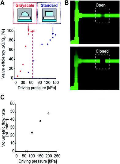
To characterize the performance of the directly embedded valves and the micropump, the threshold hydraulic pressure to completely close the microchannels was calibrated before the cell culture experiments. During the calibration, the control channels in the control layer were filled with DI water and pressurized using nitrogen gas with a pressure regulator. The inlet and outlet of the perfusion layer were connected to tubes and the gravity flow of DI water was generated at a pressure head of 400 mm. The flow rate was measured by means of the progress of the water front in the tube, and the valve efficiency was then defined by a change in relative flow rate. The efficiency of the valve fabricated by grayscale lithography increased steeply until it reached hydraulic pressure of 63 kPa compared to that of standard lithography (Fig. 4A). Taken together with the numerical simulation of a 200 × 200 μm square PDMS membrane having a threshold hydraulic pressure of 65 kPa (CoventorWare, Coventor), the measurements agree with the threshold hydraulic pressure obtained from the simulation (differing by less than 3%).39 The fluorescent images of the integrated pneumatic valve in the open and closed states, revealed that the valve was 100% closed at a hydraulic pressure of 65 kPa (Fig. 4B). On the other hand, the efficiency of the valve fabricated by standard lithography continuously increased and did not close completely due to restrictions in PDMS's mechanical deformability at the microchannel edges. The volumetric flow rate generated by the micropump was also measured by observing the moving water front without gravity flow (Fig. 4C). The measured volumetric flow rate was observed after the applied hydraulic pressure reached 65 kPa; under a driving pressure of 100 kPa, a flow rate of 26 nL min−1 was obtained at 2 Hz. At this flow rate, drugs and metabolites moved from one chamber to another in two minutes. These data show that the present microfabrication technology can achieve reliability and accurate valve and micro pump actuation.Cell culture in iHCC
To accomplish our iHCC goal, we first confirmed the applicability of our device for co-culturing two different cell types with circulation of the medium and then established an in vitro cell-based assay for reproduction of the side effects of DXR in the device.To determine whether the fabricated device allowed simultaneous culture of two different cells, we introduced hCMs and HepG2 cells into the device and cultured them (Fig. 5A). Prior to cell culture, the culture chambers were coated with extracellular matrix (ECM) components such as fibronectin, gelatin, or Matrigel at 4 °C for at least 16 hours. Matrigel was found to be a more effective ECM than fibronectin and gelatin for both cell types, in terms of cell proliferation for the first 24 hours (data not shown). When changing the medium, 10 μL of fresh culture medium for each cell type was placed in a tube and introduced from an inlet into the respective cell culture chamber using a pipette. During cell culture, iHCC was placed in a humidified incubator at 37 °C under 5% (v/v) CO2. After introducing the cells, it took approximately three hours for the cells to attach to the Matrigel-coated substrate. Because PDMS is a porous material, CO2 was able to penetrate through the PDMS of iHCC and reach the cell culture chambers. Therefore, the pH in iHCC was maintained due to the equilibrium of HCO3− and CO2. Both cell types reached over 80% confluence after one day of culture on the chip without any damage. After establishing cell culture in each chamber, we also set up a closed-loop medium circulation. For this, we used hCM medium, which was changed every 6 hours. Although hCM medium was not established for HepG2 cells, both HepG2 and hCM cells showed normal morphology as well as growth in the circulating medium (Fig. 5B and C). These results suggest that the hCM medium allowed culture of both hCMs and HepG2 cells without damage during cell culture and treatment.
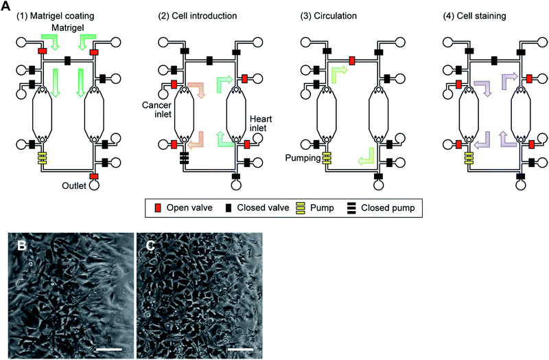 | ||
| Fig. 5 Cell culture in the iHCC. (A) Procedure for cell culture and drug testing in the iHCC. The red and black squares represent the open and closed valves, respectively. The set of three yellow squares represents a peristaltic pump comprised of three pneumatic valves. (1) To facilitate cell adhesion and growth, Matrigel was first introduced using a syringe inserted at the inlet hole, and coated in the cell culture chamber at 4 °C for at least 16 hours after which the excess Matrigel was removed. (2) Following this, both cancer and heart cells were introduced into separate chambers using a pipette and a hole adjacent to the cell culture chamber, and incubated in a humidified incubator at 37 °C for 24 hours. (3) After cell culture, medium circulation was started, with and without the drug solution, using the embedded micropumps for 24 hours. (4) Finally, DAPI was introduced and cells were incubated in a humidified incubator at 37 °C for 30 min to observe cell damage. See also ESI† (B, C) microphotograph of human primary cardiomyocytes (hCMs; B) and HepG2 cells (C) cultured in iHCC under medium circulation after 24 hours. Scale bar, 100 μm. | ||
Drug testing in iHCC
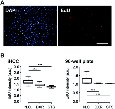
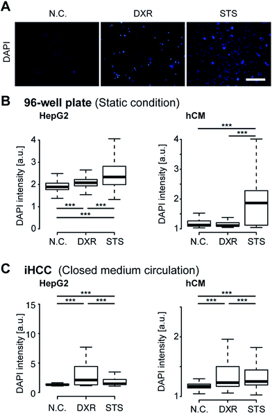
Next, we performed iHCC-based assays to evaluate the efficacy and toxicity of DXR (Fig. 6). As a comparison, a conventional cell-based assay was also performed in a 96-well plate, in which only static conditions could be applied to the cells, and the interaction between hCMs and HepG2 cells via metabolites released from cells in cell culture medium could not be observed. As a positive control (P.C.) for cell damage, staurosporine (STS)43 was used to induce apoptosis. As a negative control (N.C.), a mock solution (hCM medium supplemented with 0.1% (v/v) DMSO) was used. EdU was used as an indicator of cells in the S-phase, as DXR inhibits cell proliferation by intercalating into the genome during DNA duplication. In both experimental setups, HepG2 cells treated with 20 μM DXR reduced EdU accumulation to levels comparable to those in cells treated with STS, resulting in lower cell proliferation (Fig. 6B). This result indicated that DXR showed anti-cancer effects on HepG2 cells. We also attempted EdU staining of hCMs, but since these were non-cancerous healthy cells and do not proliferate, no EdU signal was obtained, in contrast to HepG2 cells (Fig. S1 in ESI†).For better observation of DXR-induced cell damage, DAPI fluorescent dye was used as a dead cell assay (Fig. 7A).44,45 DAPI does not pass through the intact cell membrane, but penetrates the membrane of damaged or apoptotic cells and binds to the DNA. Therefore, DAPI fluorescence is only observed for dead or apoptotic cells. To conduct a cell-based assay in a microfluidic device, in situ methods such as cell imaging9 and the use of integrated sensors22 are more suitable than other methods involving cell lysis (e.g., enzyme-linked immune-sorbent assay, western blotting or quantitative polymerase chain reaction) or secretion (e.g., secreted alkaline phosphatase assay) because of the lack of sample loss in the device and tubing. To quantitatively analyze cell damage, single-cell profiling was also conducted using both iHCC and a parallel 96-well plate. Under static conditions in the 96-well plate, the number of cells damaged by DXR increased slightly, but only for HepG2 cells (***p < 0.001, compared with N.C.), and not for the hCMs (Fig. 7B). This result indicated that DXR exerted an appropriate anti-cancer effect on HepG2 but did not cause cell damage to the hCMs. In contrast, the iHCC experiment produced different results (Fig. 7C). Following the application of closed-loop medium circulation with DXR in iHCC, the number of damaged hCMs increased significantly (***p < 0.001, compared with NC), whereas no cell damage was observed without DXR. In light of these results, we hypothesized that the cytotoxicity was attributable to DXR metabolites being released from HepG2 cells, rather than to DXR itself, which then reached the hCM cells via the circulating medium.
DXRol (doxorubicinol), a known DXR metabolite, was used to validate our hypothesis.46,47 While the side effects of DXR on cardiomyocytes and its toxicity mechanism has been intensively studied, the effects of DXRol are not known. First, we measured the levels of DXRol produced from DXR-treated HepG2 and hCM cells (Fig. 8A left panel and Fig. S2†). HepG2 cells produced 0.20 μM of DXRol in 100 μL cell culture medium by metabolizing DXR, but hCMs did not. In fact, the amount of DXR in HepG2 culture was reduced compared with that in hCM culture due to its metabolism to DXRol (Fig. 8A right panel). To investigate the cytotoxic effects of DXR and DXRol, release of lactate dehydorogenase (LDH), a well-known indicator of cell damage, was determined in the 96-well plate assay (Fig. S3†). While 20 μM DXR was cytotoxic to HepG2 cells, lower DXR concentrations did not show cytotoxicity. In terms of hCMs, DXR did not induce LDH release, indicating that DXR did not cause cell damage. In contrast, 20 μM DXRol caused cytotoxic effects in hCMs, but not in HepG2 cells. As shown in Fig. 8A, HepG2 cells produced only 0.20 μM DXRol from DXR, but this concentration did not cause cell damage to hCMs. This difference is largely due to the differences between the iHCC and 96-well plate systems. In the case of the 96-well plate, metabolites released from cells might be diluted in the cell culture medium, whereas, in the case of iHCC, the metabolites were not diluted as much due to the smaller volume used for cell culture. Therefore, metabolites released from cells in the iHCC might more effectively affect other cells than they would affect the cells in a 96-well plate. In this regard, further analysis using a 96-well plate assay and 20 μM of DXR and DXRol were used. To test the effects of DXRol on the proliferation of HepG2 cells, an EdU cell proliferation assay was carried out (Fig. S4†). As a result, DXRol significantly reduced the EdU staining intensity (***P < 0.001), indicating reduced cell proliferation; this result was similar to that obtained for DXR. Furthermore, hCMs treated with DXRol had more cell damage than hCMs treated with DXR or the N.C. (***P < 0.001; Fig. 8B). These results suggest that DXR is not toxic to healthy cardiomyocytes, but its metabolite DXRol is very toxic to cardiomyocytes.
Conclusions
In conclusion, we propose a proof of concept for recapitulation of the cardiotoxic side effects of an anti-cancer drug in vitro using a simple iHCC, which comprises a microfluidic device allowing for integrated culture of cancer and heart cells. The iHCC developed here permits (1) culture of cells from different types of tissues within a single device, (2) application of a closed circulation loop as an artificial blood circulatory system, and (3) multiple sets of different samples to be used for systematic tests. Essentially, it allows a drug to travel through tissues via the circulation loop and to produce tissue-specific metabolites. Thus, the cytotoxicity of an anti-cancer drug on cancer cells and normal cardiomyocytes can be successfully evaluated within a device, thereby recapitulating the side effects. Because this cannot be achieved using conventional cell cultureware, iHCC offers great advantages over conventional OoC/BoC platforms to accurately reproduce human physiological conditions by effectively utilizing its circulation loop to connect different tissues. Furthermore, the proposed fabrication method for on-chip integration of micro pumps is scalable and applicable for other studies. Therefore, this is the first step in recapitulating the side effects of a drug using the OoC/BoC platforms.To make more advanced BoC platforms, there are several requirements. First, the use of more functional tissues for accurate drug testing is needed and this means that three-dimensional cell culture needs to be performed in these BoC platforms. Of course, the microfluidic technique offers chemical and physical control over three-dimensional cellular environments.33,34,48–50 These advantages should allow for the generation of environments highly suitable for cells to express their functions, even in vitro.
Second, PDMS is known to absorb small molecules, such as hydrophobic molecules,19 which might influence the pharmacological results.51 Although alternatives to PDMS have been under development for a long time,39 no suitable substitutes are yet available. Therefore, a new material enabling better pharmacological studies needs to be developed.
Third, it is also important to note that the cell culture medium needs to be optimized for the tested cell types, especially, for performing BoC experiments for longer periods, such as a month or more. In this study, we used the hCM medium for both cardiomyocytes and hepatocellular carcinoma cells. This issue can be addressed by both development of the cell culture medium and design of the microfluidic device.
Fourth, it is also important to note that the results obtained using the BoC platform need to be reconciled with pharmacological data obtained in either preclinical animal studies or clinical trials. Therefore, it is also necessary to design experiments and analyses to compare iHCC-based and preclinical/clinical trial data.
Finally, we envision that by applying the recently developed induced pluripotent stem cell technology and increasing the number and complexity of tissues using advanced micro-engineering technology, this platform will be able to recapitulate physiological and pathological conditions for precise investigation of drug efficacy and toxicity, which would be a significant step toward realizing personalized medicine.
Acknowledgements
We thank Ms Minako Nakajima and Dr Misao Takemoto for their assistance with cell culture, Dr Christopher Fockenberg for his assistance in the experimental setup and programming, Mr Kouta Kobayashi for device fabrication, and Ms Yumie Tokunaga for statistical analyses. We also thank the staff at Tokyo Ohka Kogyo Co. Ltd. for the helpful discussions. Funding was generously provided by the Japan Society for the Promotion of Science (JSPS; 24656502 and 16K14660 (KK)) and Terumo Life Science Foundation. The WPI-iCeMS is supported by the World Premier International Research Centre Initiative (WPI), the Ministry of Education, Culture, Sports, Science and Technology (MEXT), Japan. A part of this work was supported by the Nanotechnology Platform Project within MEXT, Japan, through Kyoto University Nano Technology Hub. The Medical Research Support Center, Graduate School of Medicine, Kyoto University was supported by the Platform of Drug Discovery, Informatics, and Structural Life Science from MEXT, Japan.Notes and references
- M. Abou-Gharbia and W. E. Childers, J. Med. Chem., 2014, 57, 5525–5553 CrossRef CAS PubMed.
- J. Zurlo, D. Rudacille and A. M. Goldberg, Animals and Alternatives in Testing: History, Science, and Ethics, Mary Ann Liebert, 1994 Search PubMed.
- S. N. Bhatia and D. E. Ingber, Nat. Biotechnol., 2014, 32, 760–772 CrossRef CAS PubMed.
- M. B. Esch, J. M. Prot, Y. I. Wang, P. Miller, J. R. Llamas-Vidales, B. A. Naughton, D. R. Applegate and M. L. Shuler, Lab Chip, 2015, 15, 2269–2277 RSC.
- S. Selimovic, M. R. Dokmeci and A. Khademhosseini, Curr. Opin. Pharmacol., 2013, 13, 829–833 CrossRef CAS PubMed.
- J. Fukumoto and N. Kolliputi, Front. Pharmacol., 2012, 3, 205 Search PubMed.
- C. T. Ho, R. Z. Lin, W. Y. Chang, H. Y. Chang and C. H. Liu, Lab Chip, 2006, 6, 724–734 RSC.
- J. M. Prot, A. Bunescu, B. Elena-Herrmann, C. Aninat, L. C. Snouber, L. Griscom, F. Razan, F. Y. Bois, C. Legallais, C. Brochot, A. Corlu, M. E. Dumas and E. Leclerc, Toxicol. Appl. Pharmacol., 2012, 259, 270–280 CrossRef CAS PubMed.
- K. J. Jang, A. P. Mehr, G. A. Hamilton, L. A. McPartlin, S. Chung, K. Y. Suh and D. E. Ingber, Integr. Biol., 2013, 5, 1119–1129 RSC.
- H. J. Kim, D. Huh, G. Hamilton and D. E. Ingber, Lab Chip, 2012, 12, 2165–2174 RSC.
- C. A. Dickey, C. Patterson, D. Dickson and L. Petrucelli, Trends Mol. Med., 2007, 13, 32–38 CrossRef CAS PubMed.
- A. Guan, P. Hamilton, Y. Wang, M. Gorbet, Z. Li and K. S. Phillips, Nature Biomedical Engineering, 2017, 1, 0045 CrossRef.
- J. H. Sung, M. B. Esch, J. M. Prot, C. J. Long, A. Smith, J. J. Hickman and M. L. Shuler, Lab Chip, 2013, 13, 1201–1212 RSC.
- H. E. Abaci and M. L. Shuler, Integr. Biol., 2015, 7, 383–391 RSC.
- K. Kamei, Y. Hirai and O. Tabata, IEEE Nanotechnology Magazine, 2013, 7, 6–14 CrossRef.
- M. B. Esch, T. L. King and M. L. Shuler, Annu. Rev. Biomed. Eng., 2011, 13, 55–72 CrossRef CAS PubMed.
- E.-M. Materne, A. P. Ramme, A. P. Terrasso, M. Serra, P. M. Alves, C. Brito, D. A. Sakharov, A. G. Tonevitsky, R. Lauster and U. Marx, J. Biotechnol., 2015, 205, 36–46 CrossRef CAS PubMed.
- J. H. Sung, C. Kam and M. L. Shuler, Lab Chip, 2010, 10, 446–455 RSC.
- P. M. Misun, J. Rothe, Y. R. F. Schmid, A. Hierlemann and O. Frey, Microsyst. Nanoeng., 2016, 2, 16022 CrossRef CAS.
- I. Maschmeyer, A. K. Lorenz, K. Schimek, T. Hasenberg, A. P. Ramme, J. Hubner, M. Lindner, C. Drewell, S. Bauer, A. Thomas, N. S. Sambo, F. Sonntag, R. Lauster and U. Marx, Lab Chip, 2015, 15, 2688–2699 RSC.
- C. Oleaga, C. Bernabini, A. S. Smith, B. Srinivasan, M. Jackson, W. McLamb, V. Platt, R. Bridges, Y. Cai, N. Santhanam, B. Berry, S. Najjar, N. Akanda, X. Guo, C. Martin, G. Ekman, M. B. Esch, J. Langer, G. Ouedraogo, J. Cotovio, L. Breton, M. L. Shuler and J. J. Hickman, Sci. Rep., 2016, 6, 20030 CrossRef CAS PubMed.
- K. Hattori, Y. Munehira, H. Kobayashi, T. Satoh, S. Sugiura and T. Kanamori, J. Biosci. Bioeng., 2014, 118, 327–332 CrossRef CAS PubMed.
- M. Y. Rotenberg, E. Ruvinov, A. Armoza and S. Cohen, Lab Chip, 2012, 12, 2696 RSC.
- M. A. Unger, H. P. Chou, T. Thorsen, A. Scherer and S. R. Quake, Science, 2000, 288, 113–116 CrossRef CAS PubMed.
- T. Thorsen, S. J. Maerkl and S. R. Quake, Science, 2002, 298, 580–584 CrossRef CAS PubMed.
- A. J. Dy, A. Cosmanescu, J. Sluka, J. A. Glazier, D. Stupack and D. Amarie, J. Micromech. Microeng., 2014, 24, 057001 CrossRef.
- W. Park, S. Han and S. Kwon, Lab Chip, 2010, 10, 2814–2817 RSC.
- S. S. Huang, Q. H. He, X. Q. Hu and H. W. Chen, J. Micromech. Microeng., 2012, 22, 085008 CrossRef.
- A. Albini, G. Pennesi, F. Donatelli, R. Cammarota, S. De Flora and D. M. Noonan, J. Natl. Cancer Inst., 2010, 102, 14–25 CrossRef CAS PubMed.
- O. Tacar, P. Sriamornsak and C. R. Dass, J. Pharm. Pharmacol., 2013, 65, 157–170 CrossRef CAS PubMed.
- S. Yano, S. Li, Q. Han, Y. Tan, M. Bouvet, T. Fujiwara and R. M. Hoffman, Oncotarget, 2014, 5, 8729–8736 Search PubMed.
- K. Chatterjee, J. Zhang, N. Honbo and J. S. Karliner, Cardiology, 2010, 115, 155–162 CrossRef CAS PubMed.
- K. Kamei, Y. Hirai, M. Yoshioka, Y. Makino, Q. Yuan, M. Nakajima, Y. Chen and O. Tabata, Adv. Healthcare Mater., 2013, 2, 287–291 CrossRef CAS PubMed.
- K. Kamei, J. Lab. Autom., 2013, 18, 469–481 CrossRef CAS PubMed.
- Z. T. Yu, K. Kamei, H. Takahashi, C. J. Shu, X. Wang, G. W. He, R. Silverman, C. G. Radu, O. N. Witte, K. B. Lee and H. R. Tseng, Biomed. Microdevices, 2009, 11, 547–555 CrossRef CAS PubMed.
- H.-P. Chou, M. Unger and S. Quake, Biomed. Microdevices, 2001, 3, 323–330 CrossRef.
- Y. N. Xia and G. M. Whitesides, Angew. Chem., Int. Ed., 1998, 37, 550–575 CrossRef CAS.
- X. Ma, Y. Kato, F. van Kempen, Y. Hirai, T. Tsuchiya, F. van Keulen and O. Tabata, J. Microelectromech. Syst., 2015, 24, 1856–1867 CrossRef.
- Y. Kato, Y. Hirai, K. Kamei, T. Tsuchiya and O. Tabata, 18th International Conference on Solid-State Sensors, Actuators and Microsystems (TRANSDUCERS), 2015, pp. 1549–1552 Search PubMed.
- M. A. Eddings and B. K. Gale, J. Micromech. Microeng., 2006, 16, 2396–2402 CrossRef.
- J. S. Go and S. Shoji, Sens. Actuators, A, 2004, 114, 438–444 CrossRef CAS.
- T. Satoh, G. Narazaki, R. Sugita, H. Kobayashi, S. Sugiura and T. Kanamori, Lab Chip, 2016, 16, 2339–2348 RSC.
- C. A. Belmokhtar, J. Hillion and E. Segal-Bendirdjian, Oncogene, 2001, 20, 3354–3362 CrossRef CAS PubMed.
- M. Kubista, B. Akerman and B. Norden, Biochemistry, 1987, 26, 4545–4553 CrossRef CAS PubMed.
- P. Puustinen, A. Rytter, M. Mortensen, P. Kohonen, J. M. Moreira and M. Jaattela, J. Cell Biol., 2014, 204, 713–727 CrossRef CAS PubMed.
- A. D. Hanna, A. Lam, S. Tham, A. F. Dulhunty and N. A. Beard, Mol. Pharmacol., 2014, 86, 438–449 CrossRef PubMed.
- R. D. Olson, P. S. Mushlin, D. E. Brenner, S. Fleischer, B. J. Cusack, B. K. Chang and R. J. Boucek Jr, Proc. Natl. Acad. Sci. U. S. A., 1988, 85, 3585–3589 CrossRef CAS.
- S. Halldorsson, E. Lucumi, R. Gomez-Sjoberg and R. M. Fleming, Biosens. Bioelectron., 2015, 63, 218–231 CrossRef CAS PubMed.
- J. Avesar, T. B. Arye and S. Levenberg, Lab Chip, 2014, 14, 2161–2167 RSC.
- M. Mehling and S. Tay, Curr. Opin. Biotechnol., 2014, 25, 95–102 CrossRef CAS PubMed.
- E. W. Esch, A. Bahinski and D. Huh, Nat. Rev. Drug Discovery, 2015, 14, 248–260 CrossRef CAS PubMed.
Footnote |
| † Electronic supplementary information (ESI) available. See DOI: 10.1039/c7ra07716e |
| This journal is © The Royal Society of Chemistry 2017 |

