 Open Access Article
Self-assembled coronene nanofiber arrays: toward integrated organic bioelectronics for efficient isolation, detection, and recovery of cancer cells†
Po-Jung Chen,
Rou-Zhen Liu and
Yu-Sheng Hsiao*
Department of Materials Engineering, Ming Chi University of Technology, 84 Gunjuan Road, Taishan, New Taipei City 243, Taiwan. E-mail: yshsiao@mail.mcut.edu.tw; Fax: +886-2908-4091
First published on 25th July 2017
Abstract
The biological immobilization of antibodies onto geometrically controlled conducting/semiconducting nanostructures is a promising approach for directing efficient cell–substrate interactions at bioelectronic interfaces (BEIs), thereby facilitating the melding of biological systems with electronics. In this study, we employed a novel thin-film growth technology to fabricate three-dimensional (3D) organic small-molecule semiconductor-based nanofiber (NF) arrays on transparent conducting electrodes, and examined their BEI integration for the isolation, detection, and recovery of circulating tumor cells (CTCs). During normal thermal evaporation, out-of-plane nanostructures of coronene (CR), a polycyclic aromatic small molecule, readily formed through template-assisted self-assembly. We exploited the synergistic effects of controllable CR-based NF structures and anti-epithelial cellular adhesion molecule (anti-EpCAM) coatings as nanovelcro cell-affinity assays to enhance the capture efficiency of targeted CTCs, while behaving as anti-adhesive surfaces for non-targeted cells. Because of the high integration capability and high optical transparency of CR-based NFs, optimizing the binding conditions of the anti-EpCAM coatings allowed us to develop a liquid biopsy chip for the selective capture of CTCs and for the rapid/direct quantification (using a normal inverted optical microscope) of the number of captured CTCs; in addition, we designed this system such that it would allow electrically driven cell-release (using an electrochemical potentiostat). The desorption phenomena of PLL-g-PEG–biotin upon applying 20 cycles of cyclic voltammetry (voltage swept from 0 to +1.0 V) in PBS buffer triggered the electrical release of the captured CTCs from the CR-based NFs; integration of the CR-based NF substrate with an overlaid microfluidic PDMS chaotic mixer led to highly efficient cell-capture yields (>84%) at various spiked densities of MCF7 cells in a THP-1 cell solution (106 cells per mL); over 90% of the resulting cells were viable. These 3D CR-based BEI devices suggest that new opportunities abound in the design of novel organic electronics for advanced biomedical applications.
Introduction
Films of strongly π-stacked small-molecule semiconductors have garnered great attention in the production of organic electronic devices; such materials display many properties that differ from those of their bulk counterparts.1–3 Organic molecules have several features that make them attractive alternatives to inorganic materials for use in electronics, including low cost, light weight, amenability to large-scale and low-temperature processing, and mechanical flexibility.4–6 For example, organic crystals composed of semiconducting small molecules can display enhanced electrical and optical performance because of their low defect densities (resulting from self-assembly and/or crystallinity), their quantum size effects, and the simplicity of their doping at the material level.7,8 Through fine control over the surface energy and temperature of the substrates during the normal thermal evaporation process, the self-assembly of small molecules in particular has been studied extensively, allowing the construction of a variety of nanostructures for use in organic electronics. For example, the in-plane morphologies (planar structures) of small-molecule thin films have been exploited widely in organic light emitting diodes (OLEDs) and organic field-effect transistors (OFETs),9 while out-of-plane three-dimensional (3D) morphologies [nanofiber (NF) arrays] of active layers have been generally developed for organic photovoltaics (OPVs) and organic field emitters.10–14 Although the use of organic small molecule (OSM) semiconductors as device active layers has been examined for the development of organic bioelectronics,15–17 practical examples of their applications in cell-based bioelectronics have been very rare, due to the lack of reliable techniques for controlling the 3D morphologies of OSM thin films and for regulating cell–matrix interactions at the device level.Circulating tumor cells (CTCs) are shed from solid primary tumors and arrive in the peripheral bloodstream with the capability to form distant metastases; they are, therefore, potentially accessible sources for cancer diagnosis and the monitoring of disease progression. Cell phenotyping and molecular characterization of CTCs in blood samples (liquid biopsies) can provide sufficient information for monitoring the full course of the tumor-specific changes, and for gauging the efficacy of the response of patients to treatment.18 Although analytical concepts using liquid biopsies may be adapted to a variety of procedures for cancer diagnosis, the identification and isolation of CTCs in blood samples are both technically challenging, due to the extremely low concentrations of CTCs, relative to hematologic cells, in the blood (only a few to a few hundred CTCs for every billion blood cells). In addition to approaches exploiting individual physical (e.g., size, density, electric charge, deformability) and biological (e.g., surface conjugation with specific biomolecules) properties,19–21 recent research into nanostructures has revealed that the synergistic effects of surface modification and immunoaffinity can lead to the recognition and capture of CTCs with high efficiency and specificity. For example, vertical (out-of-plane) nanostructures of silicon nanopillars22–29 and nanostructured arrays of the conducting polymer poly(3,4-ethylenedioxythiophene) (PEDOT),30–32 and horizontal (in-plane) nanostructures of poly(lactic-co-glycolic acid) (PLGA),33 TiO2,34 nylon-6 NFs,35 and other nanostructures,36–38 can all serve in nanovelcro cell-affinity assays for the highly efficient capture of cancer cells. The further integration of organic 3D bioelectronic interfaces (BEIs), including conducting polymers, carbon materials, and OSM semiconductors on chips, should enhance the applications of bioelectronics in cancer research.
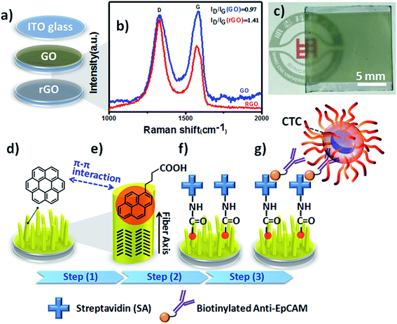
In a previous study, we found that large-scale reduced graphene oxide (rGO) coatings could transform metal-free phthalocyanine (H2Pc) films into vertical standing nanostructures on transparent indium tin oxide (ITO) electrodes during the normal thermal evaporation process.14 Although we used the preliminary results to develop OSM-based organic field emitters, we were aware that this 3D thin-film growth technology would have high integration capability and flexibility in bioelectronics and advanced biomedical applications, especially for CTC isolation and detection through the synergistic effects of surface modification and immunoaffinity. To the best of our knowledge, OSM-based NanoVelcro chips have yet to be used widely in CTC liquid biopsy assays. Accordingly, in this study we developed coronene (CR)-based NF arrays as organic 3D BEIs through optimization of the electrode identity, deposition thickness, and biofunctionalization process. Furthermore, we integrated these CR-based 3D BEIs into bioelectronics to study their ability to capture and recover CTCs (Fig. 1).
Experimental section
Materials and reagents
![[thin space (1/6-em)]](https://www.rsc.org/images/entities/char_2009.gif) :
:![[thin space (1/6-em)]](https://www.rsc.org/images/entities/char_2009.gif) 1, vol/vol; 3 mL) to dilute the pristine GO solution (1 mL). A GO film was spin-cast upon a cleaned ITO substrate. The GO film was chemically reduced in hydrazine vapor at 110 °C for 6 h to obtain the large-scale reduced GO layers on ITO glass. All devices were fabricated on patterned ITO glasses (<7 Ω sq−1) that had been cleaned sequentially with detergent, DI water, acetone, and isopropyl alcohol. After the routine cleaning, the ITO substrates were treated with air-plasma for 15 min at 18 W in low-pressure (0.2 mbar) residual air (Harrick Plasma Cleaner, PDC-32G, Harrick Scientific, NY). CR thin films were subsequently deposited onto three different kinds of transparent conducting electrode (ITO, GO-coated ITO, rGO-coated ITO) using a thermal evaporator operated at a base pressure of 5 × 10⁻⁶ torr. A commercially available CR powder (purity: 97%; Aldrich) was used as received. The sublimation of the CR powder was performed at a crucible temperature of 55 °C. For all substrates, the corresponding deposition rate, controlled by a quartz crystal microbalance (QCM), was 1 Å s−1. The deposition times for the ITO, GO/ITO, and rGO/ITO electrodes were approximately 16.7 and 83.3 min; the resulting CR thicknesses, monitored by QCM, were approximately 100 and 500 nm, respectively. The microfluidic device configuration of the CR thin film-coated rGO/ITO electrode was assembled with a chaotic mixer to obtain a PDMS microchannel with 11 channels (each continuous PDMS channel in this device was 70 μm high, 1 mm wide, and approximately 22 cm long).
1, vol/vol; 3 mL) to dilute the pristine GO solution (1 mL). A GO film was spin-cast upon a cleaned ITO substrate. The GO film was chemically reduced in hydrazine vapor at 110 °C for 6 h to obtain the large-scale reduced GO layers on ITO glass. All devices were fabricated on patterned ITO glasses (<7 Ω sq−1) that had been cleaned sequentially with detergent, DI water, acetone, and isopropyl alcohol. After the routine cleaning, the ITO substrates were treated with air-plasma for 15 min at 18 W in low-pressure (0.2 mbar) residual air (Harrick Plasma Cleaner, PDC-32G, Harrick Scientific, NY). CR thin films were subsequently deposited onto three different kinds of transparent conducting electrode (ITO, GO-coated ITO, rGO-coated ITO) using a thermal evaporator operated at a base pressure of 5 × 10⁻⁶ torr. A commercially available CR powder (purity: 97%; Aldrich) was used as received. The sublimation of the CR powder was performed at a crucible temperature of 55 °C. For all substrates, the corresponding deposition rate, controlled by a quartz crystal microbalance (QCM), was 1 Å s−1. The deposition times for the ITO, GO/ITO, and rGO/ITO electrodes were approximately 16.7 and 83.3 min; the resulting CR thicknesses, monitored by QCM, were approximately 100 and 500 nm, respectively. The microfluidic device configuration of the CR thin film-coated rGO/ITO electrode was assembled with a chaotic mixer to obtain a PDMS microchannel with 11 channels (each continuous PDMS channel in this device was 70 μm high, 1 mm wide, and approximately 22 cm long).Results and discussion
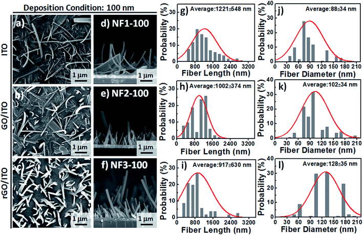
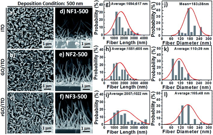
Based on observational evidence of the template-assisted self-assembly of OSM semiconductors,14 we have previously found that it is possible that rGO coatings and thermal evaporation can be used to control the vertical alignment of OSM (e.g., phthalocyanine) NFs on transparent ITO electrodes. With the goal of developing integrated transparent bioelectronic interfaces for the efficient isolation and detection of cancer cells, in this study we developed a simple approach—using three different transparent conducting electrodes (ITO, GO-coated ITO, rGO-coated ITO)—for controlling the growth of nanostructured CR-based thin films, which we studied as NF arrays for their corresponding cell-capture performance (Fig. 1). We were aware that the density of defects and degree of graphitization of GO and rGO coatings could result in different OSM NF structures after thermal evaporation deposition. Therefore, we recorded Raman spectra and calculated the ratio of the intensities of the D and G bands (ID/IG). After applying the hydrazine vapor reduction method at 110 °C for 6 h, the intensity ratio (ID/IG) changed from 0.97 for the GO-coated ITO to 1.41 for the rGO-coated ITO (Fig. 1b). This increase in the value of ID/IG suggests that the oxygen functional groups of the GO sheets were removed and more graphene domains (sp2-hybridized carbon) formed on the rGO sheets when using this chemical reduction method, while also revealing high transparency (Fig. 1c). Fig. 1d–g present our proposed adaptable modification method for preparing anti-EpCAM coatings on CR-based NF array surfaces; it can be performed readily for further studies of the critical issues of CTC isolation and detection on chips. The device configuration was based on a three-step sequence of surface modification: (1) depositing PBA through π–π interactions between pyrene and CR materials, (2) depositing SA through EDC/NHS activation of the terminal carboxylic acid groups of PBA, and (3) depositing biotinylated anti-EpCAM through SA–biotin binding. The resulting tunable CR-based NF structures presenting anti-EpCAM coatings served as nanovelcro cell-affinity assays for optimizing the rare-cell isolation.We observed different aspect ratios (ARs) and fiber densities for the 3D CR-based NFs formed on the three different electrode surfaces (ITO, GO-coated ITO, rGO-coated ITO). As indicated in Fig. 2 and 3, we adopted two different deposition conditions to control the CR-based NF arrays, monitored using a QCM with a deposition rate of 1 Å s−1, to thicknesses of 100 and 500 nm, respectively. Furthermore, we used the three different electrodes (ITO, GO/ITO, rGO/ITO) to fabricate CR-based NF thin films of various morphologies, due to their different surface energies, through thermal evaporation at a value of Tsub of 25 °C; the 3D CR-based NF arrays were formed on top of a smooth underlying layer and were associated nearly with a Stranski–Krastanov-type growth process (Fig. 2d–f and 3d–f). Notably, all-carbon-based (CR-based) NF arrays with different ARs and nanostructure densities were obtained by adjusting the deposition conditions; Fig. S1† presents the statistical analysis of the NF-related traits (e.g., fiber length, fiber diameter, aspect ratio, and number density) in this study. Samples of the 100 nm-thick NF arrays deposited on the ITO, GO/ITO, and rGO/ITO electrodes are denoted NF1-100, NF2-100, and NF3-100, where the number 100 refers to the deposition thickness of the CR-based NF arrays (monitored using a QCM). Fig. 2 displays SEM images of the 100 nm-thick of CR-based NF arrays and their size distributions. The average fiber lengths of NF1-100, NF2-100, and NF3-100 were 1221, 1002, and 917 nm, respectively; the average fiber diameters were 88, 102, and 128 nm, respectively. Interestingly, the number density of the NFs decreased in the order NF3-100 > NF1-100 ≈ NF2-100 (Fig. S1d†). Using the same sample nomenclature, the morphologies of the 500 nm-thick NF arrays deposited on the ITO, GO/ITO, and rGO/ITO electrodes (NF1-500, NF2-500, and NF3-500, respectively) revealed (Fig. 3) a decrease in the number density of the NFs in the order NF3-500 ≈ NF2-500 > NF1-500. Nevertheless, the NF densities obtained using the 500 nm-thickness deposition conditions were generally higher than those of the 100 nm-thickness conditions. The average fiber lengths of NF1-500, NF2-500, and NF3-500 were 1694, 1551, and 2007 nm, respectively; the average fiber diameters of NF1-500, NF2-500, and NF3-500 were 183, 110, and 165 nm, respectively.
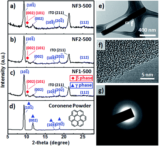
Fig. 4a–d present GIXRD spectra of the CR powders and CR films formed on the various substrates through TE at a value of Tsub of 25 °C. The GIXRD patterns of the CR powders and nanorods were indexed well to the crystal structures of β-CR and γ-CR39 and indicated polycrystalline material. The peaks of γ-CR corresponding to the (10![[1 with combining macron]](https://www.rsc.org/images/entities/char_0031_0304.gif) ), (002), (10
), (002), (10![[3 with combining macron]](https://www.rsc.org/images/entities/char_0033_0304.gif) ), (20
), (20![[2 with combining macron]](https://www.rsc.org/images/entities/char_0032_0304.gif) ) and (112) planes, indicated by blue triangles, appeared at values of 2θ of 9.30, 11.90, 17.41, 18.32, and 25.75°, respectively. Interestingly, two emergent peaks, indicated by red rhombuses, were observed at values of 2θ of 10.55 and 10.65°, corresponding to the (001) and (101) peaks, respectively, of β-CR. Furthermore, we used TEM and corresponding SAED patterns to investigate the molecular packing through substrate-assisted assembly of a single CR NF of NF3-100 after the normal thermal evaporation process. Fig. 4e displays a TEM image of CR-based NFs synthesized on the rGO-coated ITO substrate; no catalyst was evident at the tips after applying this fabrication process. HRTEM images (Fig. 4f–g) of this CR-based NF exhibited fringes, suggesting that the CR molecules were stacked in short-range order at the edges of the NF, but entangled randomly within the NF. Thus, the SAED pattern evidences only diffuse rings, indicating predominantly amorphous structures of the CR-based NFs.
) and (112) planes, indicated by blue triangles, appeared at values of 2θ of 9.30, 11.90, 17.41, 18.32, and 25.75°, respectively. Interestingly, two emergent peaks, indicated by red rhombuses, were observed at values of 2θ of 10.55 and 10.65°, corresponding to the (001) and (101) peaks, respectively, of β-CR. Furthermore, we used TEM and corresponding SAED patterns to investigate the molecular packing through substrate-assisted assembly of a single CR NF of NF3-100 after the normal thermal evaporation process. Fig. 4e displays a TEM image of CR-based NFs synthesized on the rGO-coated ITO substrate; no catalyst was evident at the tips after applying this fabrication process. HRTEM images (Fig. 4f–g) of this CR-based NF exhibited fringes, suggesting that the CR molecules were stacked in short-range order at the edges of the NF, but entangled randomly within the NF. Thus, the SAED pattern evidences only diffuse rings, indicating predominantly amorphous structures of the CR-based NFs.
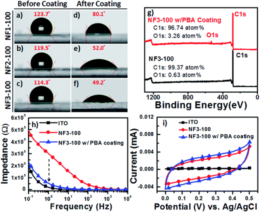
To optimize and validate the feasibility of PBA coating of our CR-based NF arrays, we conducted CA analyses of water droplets on NF1-100, NF2-100, and NF3-100 to estimate the wettability of all the carboxyl-functionalized surfaces. At room temperature, 2 μL water droplets were dispensed onto the surface of each sample, and the water CAs measured from at least five spots on every film were averaged. Fig. 5a–f reveal that the surfaces of NF1-100, NF2-100, and NF3-100 without PBA coatings were hydrophobic, with water CAs of 123.1 ± 2.8, 119.5 ± 4.9, and 114.3 ± 5.3°, respectively. After the 1 h incubations with the aqueous PBA solution at 37 °C, the surfaces of NF1-100, NF2-100, and NF3-100 with the PBA coatings had become hydrophilic, with water CAs of 80.1 ± 4.7, 52.0 ± 5.3, and 49.2 ± 6.1°, respectively. It is known that introducing surface roughness (e.g., increasing the aspect ratio and/or number density of NFs) can enhance the existing hydrophobicity of a material. We found, however, from our statistical analysis of the NF-related traits of NF1-100, NF2-100, and NF3-100 without PBA coatings, that the aspect ratio of the CR-based NFs displayed an inverse trend to the number density (Fig. S1c and d†). Presumably this behavior is why the surfaces of NF1-100, NF2-100, and NF3-100 without PBA coatings (Fig. 5a–f) were hydrophobic with similar water CAs of approximately 120° each. The different degrees of decrease in the water CAs after PBA coating suggest different surface morphologies for the NF arrays, and offer a possible explanation for the different NF diameters and densities on the various electrodes. Therefore, we suspected that the nature of the PBA immobilized on the various NF electrodes would have an important effect on the capture yields of the CTCs. To quantify how much PBA had adhered to the CR-based NF arrays, we used survey XPS to determine the changes in the atomic percentages of carbon (C) and oxygen (O) atoms on the surface of NF3-100 before and after coating with PBA. Fig. 5g presents typical XPS survey spectra of pristine NF3-100 and of NF3-100 with the PBA coating; these spectra reveal that 3.26 at% of oxygen was present after the PBA coating (arising from the carboxyl-functionalized surface), whereas oxygen atoms were scarce (0.63 at%) for the pristine NF3-100. To explore the possibility of using these surfaces in bioelectronic applications under electrochemical operation,32,40–42 we recorded EIS and CV data for ITO, NF3-100, and NF3-100 with the PBA coating, employing a standard three-electrode system in 1× PBS (0.1 M, pH 7.2). First, we used EIS to measure the impedance of the devices in the frequency range from 10−1 to 104 Hz (Fig. 5h). Although the impedance of NF3-100 at 1 Hz was approximately six times higher than that of the bare ITO electrode in 1× PBS (0.1 M, pH 7.2), due to the former's inherent hydrophobicity, the π–π stacking of the PBA coating on the NF3-100 surface would greatly enhance the ionic transport properties at the electrolyte–substrate interface, thereby decreasing the impedance close to the similar magnitude of ITO electrodes over the test frequency range. Furthermore, CV revealed a charge capacity density (CCD) for NF3-100 with the PBA coating (27.1 μC cm−2) that was higher than that of the ITO electrode (2 μC cm−2), suggesting greater capability for electrostatic surface charge accumulation; therefore, we suspected that NF3-100 with the PBA coating might behave as a functional capacitor, allowing the release of cells from biotinylated anti-EpCAM-coated CR-based NF arrays through the following cyclic potential ES.
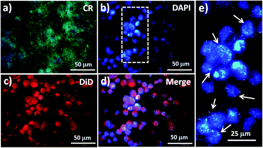
We used an inverted fluorescence microscope to obtain various views of fluorescence images of MCF7 cells captured on NF3-100. The photoluminescence (PL) of NF3-100 appeared in the range from 450 to 625 nm after UV excitation at 400 nm, with a green PL color onset at 575 nm and a maximum at 502 nm (Fig. S2a†).5 Accordingly, the CR-based NF arrays (green) appeared as nanograss structures, allowing the cell nuclei to be stained with DAPI (blue) and the cell membranes to be stained with DiD (red) for investigations of the interactions between the cells and the CR-based NF electrodes (Fig. 6). The fluorescence image in Fig. 6e of the DAPI-stained cell nuclei on the CR-based NF arrays helped us to establish the nanostructures that induced enhanced endocytosis in the captured MCF7 cells, thereby providing direct evidence for enhanced CTC capture. More interestingly, the fluorescence intensity of the nanostructures after UV excitation was higher than that of the DAPI-stained cell nuclei, presumably because of fluorescence resonance energy transfer (FRET) with the quenching capability of CR toward DAPI dyes.43,44
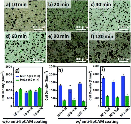
Although the fluorescence images of the MCF7 cells could be used to study the cell–substrate interactions, the overlapping fluorescence bands for the blue (DAPI) and green (CR) signals was an inconvenience when attempting to count the number of blue-stained nuclei on our CR-based NF arrays. Therefore, we investigated the optimal time required to achieve cell capture (Fig. 7a–f) through Papanicolaou staining with hematoxylin and eosin (H&E), and further used light microscopy to count the captured cell densities on the CR-based NF arrays. For the EpCAM-positive MCF7 cells, the correlation between the incubation time and the number of captured cells on NF3-100 suggested that the maximum cell-capture occurred after an incubation time of 60 min (Fig. S2b†). The cell-capture specificity of NanoVelcro chips for CTC isolation is strongly related to the degree of coating of the antibodies on the nanostructures. To investigate the synergistic effect of nanostructures and antibodies on the specific cell-capture performance when using the anti-EpCAM-coated CR-based NF arrays, we chose an EpCAM-positive cell line (human breast cancer cell line, MCF7) and an EpCAM-negative cell line (cervical cancer cell line, HeLa) as target and control cell lines, respectively (Fig. 7g–i). The pristine CR-based NF arrays (NF1-100, NF2-100, NF3-100) without the anti-EpCAM coating exhibited higher nonspecific cell adhesion for the HeLa cells than for the MCF7 cells (Fig. 7g), possibly related to the higher intrinsic strength of the cell–substrate adhesion of HeLa cells. The introduction of the SA/anti-EpCAM coating led to a distinct decrease in the number of nonspecifically bound HaLa cells, thereby enhancing the cell-capture density from 920 ± 27 (NF1-100), 889 ± 51 (NF2-100), and 950 ± 59 (NF3-100) cells per mm2 to 1340 ± 38 (NF1-100), 1089 ± 220 (NF2-100), and 1459 ± 46 (NF3-100) cells per mm2, respectively. Based on the statistical analysis of the NF-related traits of NF1-500, NF2-500, and NF3-500 in Fig. S1,† we conclude that the number-density of CR-based NFs might have played a significant role in affecting the CTC capture efficiency.
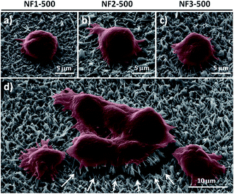
As an alternative to fluorescence imaging, we used SEM to further understand why the capture efficiency of NF3-500 was better than that of NF1-500 and NF2-500. The SEM images in Fig. 8a–d reveal that a number of outer cell membranes were indented to fold closely around the top of the CR-based NFs and that MCF7 cells having a better spreading morphology, with extended pseudopodia of the cellular structures, grasped the surface of NF3-500. In comparison, fewer cells were folded close around the NF structures and the cell spreading morphologies were poorer when adhered on the surfaces of NF1-500 and NF2-500. Furthermore, the strong cell adhesive forces between the target MCF7 cells and the NF structures arose because there were many NFs tilted in either direction, allowing specific cell interactions with the microvilli (Fig. 8d).
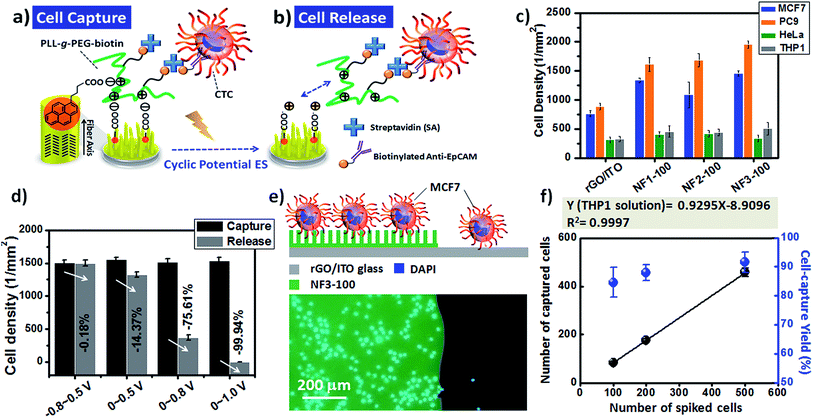
Although many cell-capture technologies have been developed for the efficient capture and isolation of rare CTCs from the blood of cancer patients, next-generation CTC chips should also have the capability of releasing the captured CTCs for downstream biological analysis.25,27–29,33,38,45 For example, in a previous report we found that nanostructured 3D electrodes functionalized with PLL-grafted polyethylene glycol (PLL-g-PEG)–biotin/SA/biotinylated-anti-EpCAM coatings can bind targeted cancer cells, but feature a passivated surface to avoid the background adsorption of nontargeted cells, while also having the ability to remove the captured CTCs under an electrochemical ES.32 More importantly, it is possible to apply this universal coating onto 3D-BEI electrodes with the goal of dynamically controlling cell–substrate interactions, allowing multiple rounds of capture and release, using different surface markers, thereby matching the requirements for a heterogeneous mixture of pooled CTCs. In this regard, we integrated PLL-g-PEG–biotin coatings onto our PBA-modified CR-based NF arrays; here, we demonstrate that the optimized NF3-100 device was applicable for CTC isolation and downstream characterization through dynamic control over the cell adhesive properties through cyclic potential ES on chips (Fig. 9a–d). In addition to MCF7 and HeLa cancer cell lines, we also tested the cell-capture efficiency of the NF3-100 device toward other EpCAM-positive (PC9) and EpCAM-negative (THP1) cell lines (Fig. 9c). Our results reveal that the synergistic effects of the (PLL-g-PEG)–biotin/SA/biotinylated anti-EpCAM-modified NF1-100, NF2-100, and NF3-100 devices preserved the higher cell-capture efficiencies of targeted MCF7 and PC9 cancer cells relative to those in control experiments of planar rGO/ITO electrodes without CR-based NFs, while mitigating the nonspecific binding of non-demanded HeLa and THP1 cells. To investigate the voltage required to ensure sufficient cell release, we applied 20 cycles of a variety of CV sweeping conditions (voltages swept from −0.8 to +0.5 V; from 0 to +0.5 V; from 0 to +0.8 V; from 0 to +1.0 V) at a scan rate of 100 mV s−1 and measured the decreases in the cell densities on the NF3-100 devices (Fig. 9d). The cell capture density on the NF3-100 device decreased by 99.94% when the sweeping voltage was in the range from 0 to +1.0 V; this cell-release performance was higher than that of the others, presumably because of the higher positive CCD level of the CR-based NF surfaces and/or more local changes in pH during a cyclic potential of ES.32,46 Furthermore, we used a trypan blue assay to evaluate the viability of the cells released from our CR-based 3D BEI devices; we observed a viability of greater than 90%, potentially sustaining the primary culture through to subculturing. Furthermore, fluorescence images of MCF7 cells captured on the NF structures of NF3-100 through the static capturing mechanism revealed greater cell-capture efficiency than that of MCF7 cells on the planar structure of rGO/ITO electrodes (Fig. 9e). In addition to these evaluations of the static cell-capture performance on different 3D CR-based BEI devices, we further integrated the NF3-100 devices with an overlaid PDMS chaotic mixer to highlight that our device platform has potential applicability with physiological relevance to CTC isolation, when spiking various MCF7 cell numbers (100, 200, and 500) into a 1 mL THP1 cell (a type of white blood cell) solution (106 cells per mL) (Fig. 9f and S3†). By integrating the basic design of a previously reported PDMS chaotic mixer with our CR-based NFs substrates,28 we found that the target cells were readily captured on NF3-100 at the optimized flow rate of 0.5 mL h−1 [isolating nearly 85% of the target MCF7 cells from non-target THP1 cell solution (106 cells per mL)] (Fig. S3†). We also used it to capture known numbers of MCF7 cells from a THP1 cell solution (106 cells per mL) at a series of densities from 100 to 500 cell per mL (Fig. 9f). Notably, the cell-capture yield at each different spiked cell density was greater than 84%; thus, our NF3-100 device with an overlaid microfluidic PDMS chaotic mixer exhibited efficient performance for isolating rare MCF7 cells from 106 cells per mL of a THP1 white blood cell solution.
Conclusions
We have employed an OSM semiconductor thin-film growth technology for the fabrication of 3D CR-based NFs on a variety of ITO electrodes, and further developed this BEI technology for integration into a bioelectronic device system that provided extremely sensitive CTC isolation and efficient cell recovery. After TE deposition, we formed CR-based NFs through template-assisted self-assembly, with a major portion of γ-CR structures and a minor portion of β-CR structures, as confirmed using GIXRD and SAED. Water CA measurements and XPS analyses confirmed the surface modifications of PBA coatings onto the NF surfaces for better use in bioconjugation. EIS and CV revealed that the π–π stacked PBA coating on the CR-based NF arrays exhibited low impedance and high CCD properties, thereby facilitating the operation and stability of BEI devices during the cyclic potential of ES. Nanovelcro cell-affinity assays using the prepared 3D CR-based NFs films revealed extremely high capture efficiencies for CTCs, ascribed to the synergistic effects of the nanoscale topography and the immobilization of the biological CTC markers. Comparing the CR-based NF array devices fabricated on the ITO, GO-modified ITO, and rGO-modified ITO electrodes, the higher fiber density of the 3D CR-based NFs in the NF3-100 devices led to cell-capture efficiency of CTCs superior to that of corresponding NF1-100 and NF2-100 devices. In addition, the longer fibers of the 3D CR-based NFs in the NF3-500 devices improved the cell-capture efficiency of CTCs relative to that of the NF3-100 devices. The sharp decrease in the degree of nonspecific cell adhesion on the PBA-modified CR-based NF arrays, compared with that on pristine CR films without the PBA modification, suggested that the negative charge of PBA and/or the specific biotin–SA interaction most likely hindered the nonspecific cell adhesion. Furthermore, the negatively charged PBA-modified CR-based NF devices facilitated dynamic control over the adsorption/desorption properties of a PLL-g-PEG–biotin coating while retaining the enhanced cell-capture performance toward CTCs; this system provided an electrically driven cell-release function through a simple and rapid ES process. The optimized electrically driven cell-release for our NF3-100 devices with PLL-g-PEG–biotin coatings occurred when applying 20 cycles of CV sweeping ES (voltage swept from 0 to +1.0 V) in 1× PBS buffer. The cell-capture yield at each different spiked cell density of MCF7 cells in a THP1 cell solution (106 cells per mL) was greater than 84% after integrating the NF3-100 with an overlaid microfluidic PDMS chaotic mixer. We hope that, through this proof-of-concept demonstration of an integrated 3D BEI device prepared through self-assembly of small-molecule semiconductors during a thermal evaporation process, our experimental results will bridge the gap between OSM devices and bioelectronics, thereby extending the range of device operating mechanisms and accelerating the development of next-generation bioelectronic medicines.Acknowledgements
This study was supported by the Ministry of Science and Technology (MOST) of Taiwan (Grant No. MOST 105-2221-E-131-039- and MOST 106-2622-E-131-003-CC2).References
- J. E. Anthony, A. Facchetti, M. Heeney, S. R. Marder and X. Zhan, Adv. Mater., 2010, 22, 3876–3892 CrossRef CAS PubMed.
- T. M. Figueira-Duarte and K. Mullen, Chem. Rev., 2011, 111, 7260–7314 CrossRef CAS PubMed.
- C. Wang, H. Dong, W. Hu, Y. Liu and D. Zhu, Chem. Rev., 2012, 112, 2208–2267 CrossRef CAS PubMed.
- H. Ma, H.-L. Yip, F. Huang and A. K. Y. Jen, Adv. Funct. Mater., 2010, 20, 1371–1388 CrossRef CAS.
- T. Sekitani and T. Someya, Adv. Mater., 2010, 22, 2228–2246 CrossRef CAS PubMed.
- X. Guo, M. Baumgarten and K. Müllen, Prog. Polym. Sci., 2013, 38, 1832–1908 CrossRef CAS.
- H. Liu, J. Xu, Y. Li and Y. Li, Acc. Chem. Res., 2010, 43, 1496–1508 CrossRef CAS PubMed.
- J. Frischeisen, D. Yokoyama, A. Endo, C. Adachi and W. Brütting, Org. Electron., 2011, 12, 809–817 CrossRef CAS.
- M. O'Neill and S. M. Kelly, Adv. Mater., 2011, 23, 566–584 CrossRef PubMed.
- Y.-S. Hsiao, W. T. Whang, S. C. Suen, J.-Y. Shiu and C.-P. Chen, Nanotechnology, 2008, 19, 415603 CrossRef PubMed.
- A. W. Hains, Z. Liang, M. A. Woodhouse and B. A. Gregg, Chem. Rev., 2010, 110, 6689–6735 CrossRef CAS PubMed.
- K.-J. Huang, Y.-S. Hsiao and W.-T. Whang, Org. Electron., 2011, 12, 686–693 CrossRef CAS.
- K.-J. Huang, Y.-S. Hsiao and W.-T. Whang, Org. Electron., 2011, 12, 1826–1834 CrossRef CAS.
- K.-J. Huang, Y.-S. Hsiao, J.-H. Huang, C.-W. Chu, P. Chen and W.-T. Whang, J. Mater. Chem., 2012, 22, 7837–7844 RSC.
- S. Lai, M. Demelas, G. Casula, P. Cosseddu, M. Barbaro and A. Bonfiglio, Adv. Mater., 2013, 25, 103–107 CrossRef CAS PubMed.
- J. Reeder, M. Kaltenbrunner, T. Ware, D. Arreaga-Salas, A. Avendano-Bolivar, T. Yokota, Y. Inoue, M. Sekino, W. Voit, T. Sekitani and T. Someya, Adv. Mater., 2014, 26, 4967–4973 CrossRef CAS PubMed.
- S. Bonetti, A. Pistone, M. Brucale, S. Karges, L. Favaretto, M. Zambianchi, T. Posati, A. Sagnella, M. Caprini, S. Toffanin, R. Zamboni, N. Camaioni, M. Muccini, M. Melucci and V. Benfenati, Adv. Healthcare Mater., 2015, 4, 1190–1202 CrossRef CAS PubMed.
- M. Yu, A. Bardia, B. S. Wittner, S. L. Stott, M. E. Smas, D. T. Ting, S. J. Isakoff, J. C. Ciciliano, M. N. Wells, A. M. Shah, K. F. Concannon, M. C. Donaldson, L. V. Sequist, E. Brachtel, D. Sgroi, J. Baselga, S. Ramaswamy, M. Toner, D. A. Haber and S. Maheswaran, Science, 2013, 339, 580–584 CrossRef CAS PubMed.
- C. Alix-Panabieres and K. Pantel, Clin. Chem., 2013, 59, 110–118 CAS.
- R. Harouaka, Z. Kang, S. Y. Zheng and L. Cao, Pharmacol. Ther., 2014, 141, 209–221 CrossRef CAS PubMed.
- L. Bai, Y. Du, J. Peng, Y. Liu, Y. Wang, Y. Yang and C. Wang, J. Mater. Chem. B, 2014, 2, 4080–4088 RSC.
- S. Wang, H. Wang, J. Jiao, K. J. Chen, G. E. Owens, K. Kamei, J. Sun, D. J. Sherman, C. P. Behrenbruch, H. Wu and H.-R. Tseng, Angew. Chem., Int. Ed., 2009, 48, 8970–8973 CrossRef CAS PubMed.
- L. Chen, X. Liu, B. Su, J. Li, L. Jiang, D. Han and S. Wang, Adv. Mater., 2011, 23, 4376–4380 CrossRef CAS PubMed.
- S. Wang, K. Liu, J. Liu, Z. T. Yu, X. Xu, L. Zhao, T. Lee, E. K. Lee, J. Reiss, Y. K. Lee, L. W. Chung, J. Huang, M. Rettig, D. Seligson, K. N. Duraiswamy, C. K. Shen and H.-R. Tseng, Angew. Chem., Int. Ed., 2011, 50, 3084–3088 CrossRef CAS PubMed.
- S. Hou, H. Zhao, L. Zhao, Q. Shen, K. S. Wei, D. Y. Suh, A. Nakao, M. A. Garcia, M. Song, T. Lee, B. Xiong, S. C. Luo, H.-R. Tseng and H.-H. Yu, Adv. Mater., 2013, 25, 1547–1551 CrossRef CAS PubMed.
- H. Liu, X. Liu, J. Meng, P. Zhang, G. Yang, B. Su, K. Sun, L. Chen, D. Han, S. Wang and L. Jiang, Adv. Mater., 2013, 25, 922–927 CrossRef CAS PubMed.
- Q. Shen, L. Xu, L. Zhao, D. Wu, Y. Fan, Y. Zhou, W. H. Ouyang, X. Xu, Z. Zhang, M. Song, T. Lee, M. A. Garcia, B. Xiong, S. Hou, H.-R. Tseng and X. Fang, Adv. Mater., 2013, 25, 2368–2373 CrossRef CAS PubMed.
- M. Lin, J. F. Chen, Y. T. Lu, Y. Zhang, J. Song, S. Hou, Z. Ke and H.-R. Tseng, Acc. Chem. Res., 2014, 47, 2941–2950 CrossRef CAS PubMed.
- J. F. Chen, Y. Zhu, Y. T. Lu, E. Hodara, S. Hou, V. G. Agopian, J. S. Tomlinson, E. M. Posadas and H. R. Tseng, Theranostics, 2016, 6, 1425–1439 CrossRef CAS PubMed.
- J. Sekine, S.-C. Luo, S. Wang, B. Zhu, H.-R. Tseng and H.-H. Yu, Adv. Mater., 2011, 23, 4788–4792 CrossRef CAS PubMed.
- Y.-S. Hsiao, S.-C. Luo, S. Hou, B. Zhu, J. Sekine, C.-W. Kuo, D.-Y. Chueh, H.-H. Yu, H.-R. Tseng and P. Chen, Small, 2014, 10, 3012–3017 CrossRef CAS PubMed.
- Y.-S. Hsiao, B.-C. Ho, H.-X. Yan, C.-W. Kuo, D.-Y. Chueh, H.-H. Yu and P. Chen, J. Mater. Chem. B, 2015, 3, 5103–5110 RSC.
- S. Hou, L. Zhao, Q. Shen, J. Yu, C. Ng, X. Kong, D. Wu, M. Song, X. Shi, X. Xu, W. H. OuYang, R. He, X. Z. Zhao, T. Lee, F. C. Brunicardi, M. A. Garcia, A. Ribas, R. S. Lo and H. R. Tseng, Angew. Chem., Int. Ed., 2013, 52, 3379–3383 CrossRef CAS PubMed.
- N. Zhang, Y. Deng, Q. Tai, B. Cheng, L. Zhao, Q. Shen, R. He, L. Hong, W. Liu, S. Guo, K. Liu, H.-R. Tseng, B. Xiong and X. Z. Zhao, Adv. Mater., 2012, 24, 2756–2760 CrossRef CAS PubMed.
- H.-C. Tseng, A.-W. Lee, P.-L. Wei, Y.-J. Chang and J.-K. Chen, J. Mater. Chem. B, 2016, 4, 6565–6580 RSC.
- Y. Li, Q. Lu, H. Liu, J. Wang, P. Zhang, H. Liang, L. Jiang and S. Wang, Adv. Mater., 2015, 27, 6848–6854 CrossRef CAS PubMed.
- F. Zhang, Y. Jiang, X. Liu, J. Meng, P. Zhang, H. Liu, G. Yang, G. Li, L. Jiang, L. J. Wan, J. S. Hu and S. Wang, Nano Lett., 2016, 16, 766–772 CrossRef CAS PubMed.
- L. Wang, H. Liu, F. Zhang, G. Li and S. Wang, Small, 2016, 12, 4697–4701 CrossRef CAS PubMed.
- J. Potticary, L. R. Terry, C. Bell, A. N. Papanikolopoulos, P. C. Christianen, H. Engelkamp, A. M. Collins, C. Fontanesi, G. Kociok-Kohn, S. Crampin, E. Da Como and S. R. Hall, Nat. Commun., 2016, 7, 11555 CrossRef CAS PubMed.
- Y.-S. Hsiao, C.-C. Lin, H.-J. Hsieh, S.-M. Tsai, C.-W. Kuo, C.-W. Chu and P. Chen, Lab Chip, 2011, 11, 3674–3680 RSC.
- C.-H. Lu, Y.-S. Hsiao, C.-W. Kuo and P. Chen, Biochim. Biophys. Acta, 2013, 1830, 4321–4328 CrossRef CAS PubMed.
- Y.-S. Hsiao, C.-W. Kuo and P. Chen, Adv. Funct. Mater., 2013, 23, 4649–4656 CrossRef CAS.
- K. Takazawa, J. Inoue and K. Mitsuishi, Nanoscale, 2014, 6, 4174–4181 RSC.
- J. Choi, W. Lee, C. Sakong, S. B. Yuk, J. S. Park and J. P. Kim, Dyes Pigm., 2012, 94, 34–39 CrossRef CAS.
- S. Hou, H. Zhao, L. Zhao, Q. Shen, K. S. Wei, D. Y. Suh, A. Nakao, M. A. Garcia, M. Song, T. Lee, B. Xiong, S. C. Luo, H. R. Tseng and H. H. Yu, Adv. Mater., 2012, 25, 1547–1551 CrossRef PubMed.
- O. Guillaume-Gentil, Y. Akiyama, M. Schuler, C. Tang, M. Textor, M. Yamato, T. Okano and J. Vörös, Adv. Mater., 2008, 20, 560–565 CrossRef CAS.
Footnote |
| † Electronic supplementary information (ESI) available. See DOI: 10.1039/c7ra07515d |
| This journal is © The Royal Society of Chemistry 2017 |

