 Open Access Article
Graphene/MnO2 aerogel with both high compression-tolerance ability and high capacitance, for compressible all-solid-state supercapacitors†
Peng Lv *,
Xun Tang and
Wei Wei*
School of Optoelectronic Engineering, Nanjing University of Posts & Telecommunications, Nanjing 210023, China. E-mail: lvp@njupt.edu.cn; Fax: +86-25-85866400; Tel: +86-25-85866400
First published on 6th October 2017
Abstract
Foam-like graphene with attractive characteristics has been proposed as a promising electrode configuration for compressible supercapacitors. However, current foam-like graphene electrodes are limited by either low compressibility or low capacity. Herein, we used a superelastic graphene aerogel as a conductive backbone and deposited pseudocapacitive materials (MnO2) into it to obtain a novel compressible electrode with both high compression-tolerance ability and high capacitance. The as-prepared graphene/MnO2 aerogel withstands 90% repeated compression cycling without any structural collapse and peel-off of MnO2 spheres from the graphene cell walls. All-solid-state supercapacitors based on graphene/MnO2 aerogel electrode were assembled to evaluate the electrochemical performances. The gravimetric capacitance of graphene/MnO2 aerogel reaches 320 F g−1 and can retain 94% even under 90% compressive strain. Moreover, a volumetric capacitance of 66.1 F cm−3 is achieved, which is much higher than that of other carbon-based compressible electrodes. Furthermore, several compressible all-solid-state supercapacitors can be integrated and connected in series to enhance the overall output voltage, which offers the potential to meet the needs of practical applications.
1. Introduction
Recently, the rapid development of wearable and portable electronic devices has created demand for suitable energy storage devices, which should have the capability to withstand high levels of strain, such as stretching, bending, or compression, without loss of energy storage performance and reliability.1–3 Among various energy storage devices, all-solid-state supercapacitors stand out as a promising solution, due to their high power density, long cycle life, and enhanced safety, transcending liquid-electrolyte-based energy storage devices that may suffer from the possible leakage of electrolytes under high levels of strain.4–6 Recent years have seen many continuous efforts and achievements in developing bendable and stretchable supercapacitors based on carbon-based electrode materials with outstanding mechanical performances.7–10 However, the reverse case, the design and development of compressible supercapacitors, has rarely been reported, although compression is one of the most influential factors in the performances of strain-tolerant supercapacitors. A successful compressible supercapacitor should be able to retain its performance under various compression conditions, which mainly depends on suitable configuration and materials. As the core component of compressible supercapacitors, the electrodes must be resilient and durable. Nevertheless, most of the conventional electrode materials cannot retain their functions, due to electrode destruction or deformation under high levels of compression strain.11Foam-like carbon materials with a highly porous structure and robustness under mechanical compression have been studied for their suitability as compressible electrodes.12–15 Among various carbon materials, foam-like graphene materials have attractive characteristics, such as high compressibility, excellent electrical conductivity, large specific surface area and self-supporting structure,16–19 showing great potential as highly compression-tolerant electrodes. Several studies of foam-like graphene materials as compressible supercapacitor electrodes have been reported (Table 1),20–24 which can be classified into two categories: graphene aerogels and graphene/pseudomaterial composites. Although some progress has been made, there are still some challenges: these foam-like graphene materials cannot possess high compression-tolerant ability and high capacitance simultaneously. For graphene aerogels, such as cross-linked graphene aerogel20 and graphene-coated carbon nanotube aerogel,21 although they can bear a high compressive strain of 90%, their specific capacitances are still unsatisfying because of their electric double-layer storage mechanism. For the graphene/pseudomaterial composites, although the introduction of pseudomaterials, such as polypyrrole (PPy), polyaniline (PANI) and MnO2, can enhance the specific capacitances of the electrodes, they still suffer from inferior compression-tolerance ability. For example, the elastic deformation of melamine foam/graphene/PPy sponge22 is limited by the compressibility of the melamine foam substrate (maximum recoverable compressive strain is only 75%); graphene/PPy foam23 cannot retain elasticity even under dry conditions; and graphene–carbon nanotube/MnO2 aerogel24 shows recoverable compressive strain of only 50%, which is much lower than that of graphene–carbon nanotube aerogel (90%).21 Hence, for developing high-performance compressible electrodes, there is an urgent need to design and synthesise a novel foam-like graphene material with both high compression-tolerance ability and high capacitance.
| Materials | Uncompressed capacitance | Compressive strain | Compressed capacitance | Content and mass loading of pseudomaterials | Test conditions | Ref. |
|---|---|---|---|---|---|---|
| Cross-linked graphene aerogel | 90 F g−1 | 90% | 130 F g−1 | — | 10 mV s−1 | 20 |
| 0.94 F cm−3 | 13.6 F cm−3 | |||||
| Graphene–carbon nanotube aerogel | 37 F g−1 | 90% | 45 F g−1 | — | 1 A g−1 | 21 |
| 0.5 F cm−3 | 6 F cm−3 | |||||
| Melamine foam/graphene/PPy sponge | 411 F g−1 | 75% | 329 F g−1 | 3.92 wt% | 10 mV s−1 | 22 |
| N.A. | ||||||
| Graphene/PPy foam | 350 F g−1 | 50% | 350 F g−1 | N.A. | 1.5 A g−1 | 23 |
| 14 F cm−3 | 28 F cm−3 | 6.7–7.4 mg cm−2 | ||||
| Graphene–carbon nanotube/MnO2 aerogel | 98 F g−1 | 50% | 106 F g−1 | 17 wt% | 2 mV s−1 | 24 |
| 1.5 F cm−3 | 3.3 F cm−3 | 0.4 mg cm−2 | ||||
| PANI–carbon nanotube–sponge | 216 F g−1 | 60% | 210 F g−1 | 65 wt% | 0.64 A g−1 | 13 |
| 3.4 F cm−3 | 4.1 mg cm−2 | |||||
| Carbon nanotube@PPy@MnO2 sponge | 305 F g−1 | 50% | 275 F g−1 | 61.9 wt% | 2 mV s−1 | 28 |
| 9.6 F cm−3 | 16.1 F cm−3 | N.A. | ||||
| Graphene/MnO2 aerogel | 320 F g−1 | 90% | 302 F g−1 | 68 wt% | 1 A g−1 | This work |
| 7.0 F cm−3 | 66.1 F cm−3 | 7.0 mg cm−2 |
Recently, there have been several reports of graphene aerogels/foams with superelasticity (recoverable compressive strain ≥90%) prepared by freeze casting,25,26 chemical vapor deposition27 and air-bubble template18 methods. Combining pseudomaterials with these superelastic graphene materials is a feasible strategy to achieve both high capacitance and high compression-tolerance ability. However, no relevant studies based on this strategy can be found in the literature up to now. Herein, we introduced a pseudomaterial (MnO2) into a superelastic graphene aerogel (maximum recoverable compressive strain = 90%) using the electrochemical deposition method to obtain high-performance compressible electrodes. In the graphene/MnO2 aerogel, MnO2 spheres are tightly coated on the surface of the graphene sheets during the compression–recovery process. This strong interaction between MnO2 and graphene sheets leads to not only the improvement of gravimetric capacitances but also the high stability of gravimetric capacitances under compression–recovery cycling. In addition, the graphene/MnO2 aerogel electrodes deliver a much higher volumetric capacitance (66.1 F cm−3) than that of other compressible carbon-based electrodes.
2. Experimental
2.1 Preparation of compressible graphene/MnO2 aerogel
Graphene oxide (GO) was prepared by oxidation of flake graphite according to the modified Hummers' method.29,30 The processes of preparing superelastic graphene aerogel were described in a previous study.25 In a typical preparation procedure, GO aqueous dispersion (4 mg mL−1, 12 mL) was first mixed uniformly with L-ascorbic acid (100 mg) by stirring for 30 min. Then the mixture solution was poured into glass vials and heated for 30 min at 90 °C for synthesis of partially reduced graphene hydrogel. The obtained hydrogel was treated by the freeze–thaw process in the refrigerator (−20 °C) and at room temperature. Subsequently, a further reduction process for the freeze-recast hydrogel was carried out for 5 h at 95 °C using the initial reductant (L-ascorbic acid) to obtain completely reduced graphene hydrogel. Finally, the graphene hydrogel was subjected to dialysis in deionized water and dried at 50 °C for 48 h to obtain the superelastic graphene aerogel.For preparing the graphene/MnO2 aerogel, the as-prepared graphene aerogel was immersed into a 0.1 M Mn(CH3COO)2 and 0.01 M Na2SO4 mixed aqueous solution under vacuum for 6 h to allow the graphene aerogel to fully absorb the mixed solution. Electrochemical deposition of MnO2 was carried out by the galvanostatic method using a three-electrode setup, where the graphene aerogel was used as the working electrode, a platinum electrode as the counter electrode, and a Ag/AgCl electrode as the reference electrode. The electrochemical deposition was performed at a constant current density of 1 mA cm−2 with deposition time of 5–40 min. After electrochemical deposition, the graphene/MnO2 aerogel was washed with deionized water and dried at 60 °C for 24 h. The mass content of MnO2 in the graphene/MnO2 aerogel was obtained by calculating the weight difference of the working electrodes.
2.2 Fabrication of compressible all-solid-state supercapacitors
The compressible all-solid-state supercapacitor was fabricated by a simple approach, which is described in previous studies.4,5,12,13 In a typical assembly process, the PVA/H2SO4 gel electrolyte was first prepared through mixing H2SO4, PVA powder and deionized water according to the mass ratio of 4![[thin space (1/6-em)]](https://www.rsc.org/images/entities/char_2009.gif) :
:![[thin space (1/6-em)]](https://www.rsc.org/images/entities/char_2009.gif) 5
5![[thin space (1/6-em)]](https://www.rsc.org/images/entities/char_2009.gif) :
:![[thin space (1/6-em)]](https://www.rsc.org/images/entities/char_2009.gif) 50. Subsequently, the mixture was stirred for 30 min at 80 °C to form a clear electrolyte. After that, the graphene/MnO2 aerogels with a thickness of ∼5 mm soaked in the PVA/H2SO4 gel electrolyte for 30 min. By vaporizing the reminder water, the gel electrolyte adhered on the cell walls of aerogels. Then two pieces of the aerogels were placed onto two poly(ethylene terephthalate) (PET) substrates separated by Au (∼100 nm). The as-prepared two electrodes sandwiched with a separator containing saturated electrolyte were assembled under pressure and subsequently kept in a fume hood to remove the excess water. Finally, the compressible all-solid-state supercapacitor was obtained.
50. Subsequently, the mixture was stirred for 30 min at 80 °C to form a clear electrolyte. After that, the graphene/MnO2 aerogels with a thickness of ∼5 mm soaked in the PVA/H2SO4 gel electrolyte for 30 min. By vaporizing the reminder water, the gel electrolyte adhered on the cell walls of aerogels. Then two pieces of the aerogels were placed onto two poly(ethylene terephthalate) (PET) substrates separated by Au (∼100 nm). The as-prepared two electrodes sandwiched with a separator containing saturated electrolyte were assembled under pressure and subsequently kept in a fume hood to remove the excess water. Finally, the compressible all-solid-state supercapacitor was obtained.
2.3 Materials characterization and electrochemical measurements
The chemical structure of the graphene/MnO2 aerogel was characterized by X-ray photoelectron spectroscopy (XPS), which was performed on a Kratos-Axis spectroscope using an Al Kα X-ray source for excitation. The X-ray diffraction pattern of the graphene/MnO2 aerogel was collected by a Bruker D8 Micro with Cu Kα radiation (k = 0.15, 418 nm, 40 kV, and 40 mA). Raman spectroscopy (RM3000, Renishaw) was performed using a laser excitation wavelength of 514.5 nm. The microstructure of the aerogels was observed using a Hitachi S-4800 scanning electron microscope (SEM) equipped with energy dispersive spectroscopy (EDS). The N2 adsorption and desorption isotherms were measured at 77 K in a liquid nitrogen bath using a NOVA-2000 adsorption instrument. The Brunauer–Emmett–Teller specific surface area of the samples was measured. The pore volume and pore size distribution were obtained using the Barrett–Joyner–Halenda method. Transmission electron microscopy (TEM) observations were performed by an FEI-Tecnai G2 F20 at 200 kV. Compression tests were carried out on an Instron-5566 with a strain rate of 200 mm min−1. The electrical conductivities under various compressive strains were measured by the two-probe method. During the measurement, two copper sheets served as electrodes to connect the aerogels to a Keithley 2410 Source Meter instrument.The electrochemical characteristics of the supercapacitor were investigated by cyclic voltammetry (CV), galvanostatic charge/discharge (GCD) and electrochemical impedance spectroscopy, using a CHI660E electrochemical workstation. The gravimetric capacitance (Cg) and volumetric capacitance (CVol) of the compressible capacitor electrodes were calculated from the GCD curves using the following eqn (1) and (2):
| Cg = 4 × I × Δt/m × ΔV | (1) |
| CVol = ρ × Cg | (2) |
The energy density (E) and power density (P) of the supercapacitor were calculated according to the following formulas.
| E = Cg × ΔV2/8 × 3.6 | (3) |
| P = (3600 × E)/Δt | (4) |
3. Results and discussion
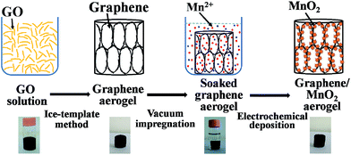
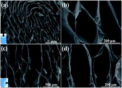
The preparation of the compressible graphene/MnO2 aerogel is illustrated in Fig. 1. Firstly, the superelastic graphene aerogel was prepared by the ice-template method.26 Then the as-prepared graphene aerogel was immersed into precursor solution under vacuum conditions to make it fully absorb the solution. Finally, MnO2 was loaded on the cell walls of the graphene aerogel by electrochemical deposition.The microstructure of the graphene aerogel with a density of 8.5 mg cm−3 was observed under SEM as shown in Fig. 2. The SEM images from top-view and side-view angles show the oriented cellular and honeycomb-like structure of the graphene aerogel. The graphene layers in the graphene aerogel are closely packed and well oriented in a parallel manner. As mentioned in previous studies, strongly oriented cells and a honeycomb-like structure will endow the graphene aerogel with mechanical robustness and superelasticity.26,31–33 In addition, it is worth noting that the graphene aerogel exhibits large pore dimensions of the order of hundreds of micrometers (about 100–500 μm), due to the low cooling rate during the freeze-recasting process,26 which is important for the homogeneous deposition in the subsequent step.34,35
After the electrochemical deposition process, the microstructure of the aerogel was observed. As shown in Fig. S1,† in contrast to the smooth surface of the cell walls in the graphene aerogel, after the deposition process we find abundant pompon-like spheres attached on the graphene cell walls. Fig. S2† presents the evolution of the morphology corresponding to various deposition times (5, 10, 20, 30, 40 minutes). With increasing deposition time, both the amount and size of the spheres gradually increase until the whole surface of the graphene cell walls is fully covered after 40 minutes of deposition. The mass contents and mass loadings of MnO2 in the graphene/MnO2 aerogels after various deposition times are shown in Table S1.† Fig. 3a–d show the microstructure of the graphene/MnO2 aerogel after 30 minutes of deposition. The oriented cellular structure and the honeycomb-like architecture of the graphene aerogel are well preserved, without any collapse during the electrochemical deposition process (Fig. 3a). In the SEM images at various magnifications (Fig. 3b–d), we can see pompon-like spheres with a diameter of ∼0.5 μm, which are composed of multiple MnO2 nanoflakes. These MnO2 spheres are homogeneously distributed on the graphene cell walls even in the inner portion of the graphene aerogel, which is attributed to the fact that the macroporous structure and large cell dimensions of the graphene aerogel enable fast flux and uniform penetration of the precursor solution into the interior zone of the aerogel. The EDS mapping results of C, O and Mn (Fig. 3e–g) also confirm the homogeneous distribution of the element Mn on the graphene cell walls. In addition, the rough MnO2 spheres also lead to an increase of the specific surface area (207 m2 g−1) of the graphene/MnO2 aerogel (deposition time of 30 min) compared to the pure graphene aerogel (72 m2 g−1), as well as an increased percentage of pores with sizes in the range of 1.5–100 nm (Fig. S3†).
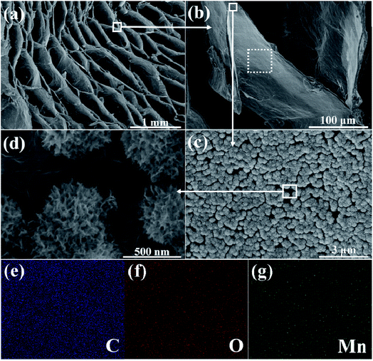 | ||
| Fig. 3 (a–d) SEM images, at various magnifications, of the graphene/MnO2 aerogel after 30 minutes of deposition; (e–g) elemental mapping results (C, O and Mn) of the selected area in (b). | ||
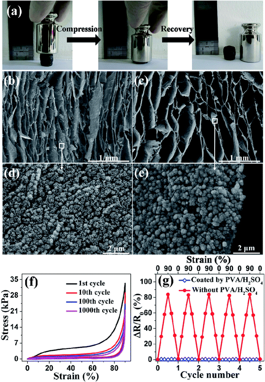
TEM was performed to further study the graphene/MnO2 aerogel. Because the longest deposition times resulted in MnO2 spheres that were too large to be observed by TEM, we chose the sample with the deposition time of 10 min to characterize the microstructure. As shown in Fig. 4a and b, the MnO2 spheres are composed of numerous ultrathin nanoflakes in intimate contact with graphene sheets. It is noteworthy that, during the preparation of TEM specimens, the MnO2 spheres are tightly coated on the graphene sheets and had not peeled off even after the sonication process, indicating the strong interaction between the MnO2 spheres and the graphene sheets. XPS analysis was performed to further characterize the composition of the as-prepared graphene/MnO2 aerogel. Fig. 4c shows the XPS spectrum, with Mn 3s, Mn 2p and O 1s peaks indicating the existence of MnO2 in the aerogel.36,37 As shown in Fig. 4d, the O 1s spectrum is deconvoluted into three constituents corresponding to Mn–O–Mn bond (529.9 eV) of the tetravalent oxide, Mn–O–H bond (531.3 eV) of the hydroxide, and H–O–H bond (532.3 eV) of water.38 The amount of MnO2 is determined to be 65%, indicating tetravalent oxide to be the dominant oxidation state of manganese oxide. X-ray diffraction was also performed to study the crystal phase of MnO2 in the aerogels. As shown in Fig. S4,† the relatively broad and low-intensity peaks indicate that MnO2 is in an amorphous state, which is favourable for supercapacitor applications.39,40 The Raman spectra of the graphene aerogel before and after MnO2 deposition are shown in Fig. S5.† In the Raman spectrum of the graphene/MnO2 aerogel, in addition to the characteristic D and G peaks at 1340 cm−1 and 1590 cm−1 from graphene, two other peaks are observed at 570 cm−1 and 650 cm−1, which are characteristic peaks of the Mn–O lattice.34 The intensity ratio of the D and G bands (ID/IG) can be used to characterize structural defects or damage in the graphene aerogel as a result of MnO2 deposition. The values of ID/IG before (1.15) and after (1.14) MnO2 deposition are similar, indicating that MnO2 deposition does not damage the underlying graphene aerogel. As described in previous studies,16,26 graphene aerogels synthesized by the ice-template method can display superelasticity. The mechanical performances of the graphene/MnO2 aerogel (deposition time of 30 min) were measured by compression experiments. As shown in Fig. 5a and Movie 1,† the graphene/MnO2 aerogel can be squeezed into a pellet under manual compression. Once the external pressure is removed, the aerogel is able to almost completely recover to its original shape rapidly. It reveals that the graphene aerogel maintains its superelasticity after the deposition process. This reversible compression–recovery process is also reflected by the inner microstructure of the graphene/MnO2 aerogel. As can be seen from Fig. 5b, the initial honeycomb structure is considerably densified under compression, while keeping its continuous configuration. Once released, the graphene/MnO2 aerogel rapidly recovers to the initial state without any collapse of the honeycomb structure (Fig. 5c). In addition, the MnO2 spheres are tightly coated on the surface of the graphene cell walls without any peel-off during the compression–recovery process (Fig. 5d and e).
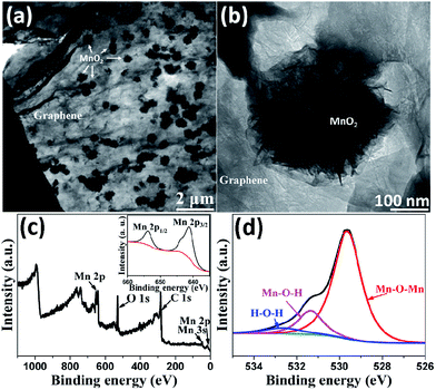 | ||
| Fig. 4 (a, b) TEM images of graphene/MnO2 aerogel after 10 minutes of deposition; (c) XPS survey spectrum of graphene/MnO2 aerogel; (d) O 1s peaks and the fitting results. | ||
The results of cyclic compression testing with maximum compressive strain up to 90% for the graphene aerogel and graphene/MnO2 aerogel are shown in Fig. S7† and 5f, respectively. The similarity of these curves verifies that the graphene aerogel retains its integrity after the deposition process. The loading process of the graphene aerogel shows the characteristic behavior of porous foam-like materials, with three distinct regions, including the elastic region, plateau region and densification region, similar to the observations in previous studies.16,26 When the graphene/MnO2 aerogel is compressed for 1000 cycles at 90% strain, it can still recover to its original volume and retain 64% of the original compressive stress. This suggests that the graphene/MnO2 aerogel can be recycled as a compressive material.
The electrical properties of the graphene/MnO2 aerogel (deposition time of 30 min) with and without solid electrolyte (PVA/H2SO4) coating were also studied. In the graphene/MnO2 aerogel, the neighbouring graphene cell walls come into contact with each other at high compressive strain, leading to rapid decline of their resistance (Fig. 5g). However, for the electrodes of compressible supercapacitors, it is of great importance to retain the resistance of the electrodes in the supercapacitors under various strains.13 After coating a layer of PVA/H2SO4 solid electrolyte on the cell walls of the graphene/MnO2 aerogel, the PVA/H2SO4 layer prevents contact between neighbouring conductive graphene cell walls at high compressive strain, resulting in negligible variation of their resistance (Fig. 5g). In addition, the resistance of the graphene/MnO2 aerogel coated with PVA/H2SO4 remains nearly constant during long-term compression/release cycling (Fig. S7†). Therefore, the graphene/MnO2 aerogel is a suitable material for the compressible electrodes of all-solid-state supercapacitors.
CV measurement in a three-electrode system was employed to demonstrate the electrochemical performance of the graphene/MnO2 aerogel. Fig. S8a† compares the CV curves of graphene aerogel and graphene/MnO2 aerogels with different deposition times at the same scan rate of 10 mV s−1. The MnO2 functionalization causes higher current density and enlarged curve area, indicating the improvement of specific capacitance. Because the close-packed structure of MnO2 will lead to the deterioration of its electrochemical properties, we have optimized the MnO2 mass content by controlling the deposition time (Fig. S8b†). By comparing the specific capacitance as a function of deposition time, we obtained the optimized deposition time of 30 min, corresponding to a MnO2 mass content of 68 wt% and a specific capacitance of 398 F g−1. Thus, all subsequent investigations of the graphene/MnO2 aerogel in supercapacitor devices in this work were based on a deposition time of 30 min. In addition, we also deposited MnO2 on a commercially available carbon material (carbon cloth, CC) (Fig. S8†) and investigated the effect of the carbon backbone on the electrochemical performance. The graphene/MnO2 aerogel with a similar mass loading of MnO2 shows a higher specific capacitance than the CC/MnO2 composite. This may be attributed to the fact that the graphene aerogel backbone provides a 3D continuous conductive path for efficient electron transfer, a large surface area for loading MnO2, and an interconnected macroporous structure for homogeneous deposition of MnO2.
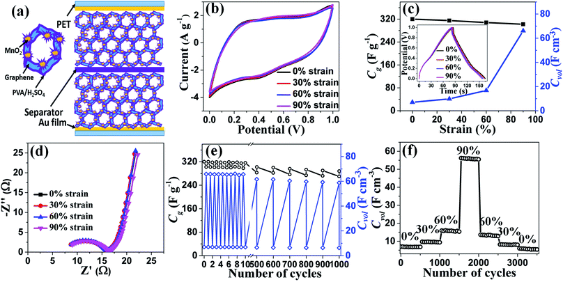
To demonstrate the capacitive performances of graphene/MnO2 aerogel as compressible electrodes, we fabricated a symmetric all-solid-state supercapacitor with an integrated configuration (Fig. 6a). As shown in Fig. 6b, the graphene/MnO2 aerogel electrodes exhibit similar CV characteristics (scan rate of 20 mV s−1) in the compression state (strain of 30%, 60% and 90%) compared with the original state, indicating the impressive electrochemical stability of the supercapacitor device under a range of compressive strains. This stability is also confirmed by the GCD curves of the electrodes under various compressive strains at a current density of 1 A g−1 (in the inset of Fig. 6c), in which only a very slight deviation is observed even under 90% strain. This excellent electrochemical stability of the graphene/MnO2 aerogel electrodes is attributed to their robust mechanical performance and stable structure under compression. As mentioned above, there is no collapse of the continuous structure, no peel-off of MnO2 spheres from the graphene cell walls (Fig. 5b), and negligible change of resistance of the electrodes (Fig. 5g) even under high compression, characteristics which are important for electron transport, stable conductivity and minimizing capacitance loss. In addition, the electrochemical impedance spectrum of the as-prepared supercapacitor was also measured (Fig. 6d). The Nyquist plots consist of a typical semicircle in the high-frequency region and a straight line in the low-frequency region. The graphene/MnO2 electrodes show similar Nyquist plots in initial and compressed states (strain of 30%, 60% and 90%), testifying to their compression-tolerant ability.
The gravimetric capacitances of the graphene/MnO2 aerogel electrodes under various compressive strains were calculated from the discharge slope (Fig. 6c). The gravimetric capacitance of the electrodes in a typical two-electrode system reaches 320 F g−1 in the uncompressed state. As shown in Table 1, this value for gravimetric capacitance is much higher than that of the compressible graphene aerogel,20,21 and comparable to the compressible graphene/conducting polymer foam.22,23 The coulombic efficiency of graphene/MnO2 is about 94%, which is comparable to the case of previously reported carbon-based supercapacitor electrodes.41–43 When 90% strain is applied to the all-solid-state supercapacitor, the capacitance retention is 94%, which is comparable to the case of previously reported compressible all-solid-state supercapacitors with carbon-based electrodes.4,13,23,28 It is noteworthy that the volumetric capacitances of the graphene/MnO2 aerogel electrodes are dramatically enhanced after 60% strain, and finally reach the maximum value of 66.1 F cm−3 under 90% strain (Fig. 6c), which is much higher than that of other compressible carbon-based electrodes (Table 1).13,20–23,28 The significant increase of volumetric capacitance arises from the negligible decline of the gravimetric capacitance and dramatic increase of the density of the graphene/MnO2 aerogel electrodes during the compression. When the electrodes are subjected to a compressive strain of 90%, their density is increased to 10 times the original value, while the gravimetric capacitance declines by only 6%. Thus, according to eqn (2), the volumetric capacitance of the electrodes at 90% strain is up to 9.4 times that of the electrodes at the uncompressed state.
In order to study the reversible compressibility and durability of the compressible all-solid-state supercapacitor based on graphene/MnO2 aerogel electrodes, its cycle stability was investigated by GCD at 1 A g−1. Under both static (constant compressive strain) and dynamic (repeated compression/release) conditions, there is only slight fluctuation of capacitance for 1000 charge/discharge cycles (Fig. 6e). To measure the long-term durability of the supercapacitor, compressive strains of 0%, 30%, 60% and 90% were each applied for 500 charge/discharge cycles and, finally, recovered to the fully released state (Fig. 6f). Relative to the original volumetric capacitance of the graphene/MnO2 aerogel electrodes, 78% is preserved after 3500 charge/discharge cycles under the various compression conditions. Energy density and power density are also two key factors to evaluate the performance of supercapacitors. The energy density and power density values for the supercapacitors were calculated using the GCD curves (Fig. S10a†) and plotted in Fig. S10b.† As seen from the Ragone plot, the maximum energy density and power density are 11.1 W h kg−1 and 2.5 kW kg−1, respectively. The obtained values are at a moderate level (compared with other similar all-solid-state supercapacitors).10,12,13,44,45
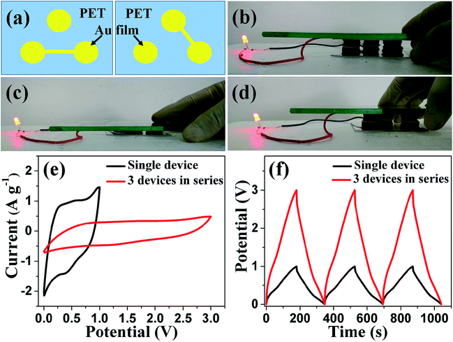
In general, the product current and output voltage in a single supercapacitor are too low for practical applications. Therefore, several supercapacitors should be connected together either in parallel or in series to improve the product current or output voltage. In addition, to retain the compression-tolerant ability, it is necessary to assemble several supercapacitors into one integrated unit. We integrated three compressible supercapacitors into one unit and interconnected them together in series by designing Au film patterns on PET substrates, as illustrated in Fig. 7a. The resultant integrated device can power a red-light-emitting diode when fully charged (Fig. 7b). In addition, this integrated device works well during compression/release cycling, as shown in Fig. 7b–d and Movie 2,† showing a good compression-tolerant ability. The integrated device was also evaluated by CV and GCD measurements. As shown in Fig. 7e and f, the potential window is enhanced from 1.0 V for a single supercapacitor to 3.0 V for the tandem device. Furthermore, the charge/discharge time and the product current (reflected by the area of the CV curves) remain unchanged for the tandem devices compared with the individual supercapacitor, suggesting that the capacitive performance of each single supercapacitor in the integrated device is well maintained.
4. Conclusion
We demonstrated a reversibly compressible graphene/MnO2 aerogel with high electrochemical performance characteristics for a compressible all-solid-state supercapacitor. The as-prepared graphene/MnO2 aerogel is durably tolerant to large compressive strain without any structural collapse and peel-off of MnO2 spheres. The electrochemical performance characteristics of the all-solid-state supercapacitor based on graphene/MnO2 aerogel electrodes are largely invariant to compressive strains up to 90%, with no significant decline of gravimetric capacitance. Importantly, we exploited this compressibility and recoverability to achieve a high volumetric capacitance of 66.1 F cm−3, which is much higher than that of other carbon-based compressible electrodes. Furthermore, several supercapacitors can be integrated and interconnected together on one chip to power electronic devices. This work will provide a way towards advanced applications of supercapacitors in the area of compression-tolerant energy storage devices.Conflicts of interest
There are no conflicts to declare.Acknowledgements
This work was supported by the National Natural Science Foundation of China (Grant No. 51503102) and the Natural Science Foundation of Jiangsu Province, China (Grant No. BK20140869).References
- Y. Li, J. Chen, L. Huang, C. Li, J.-D. Hong and G. Shi, Adv. Mater., 2014, 26, 4789–4793 CrossRef CAS PubMed.
- H. Hu, Z. Zhao, W. Wan, Y. Gogotsi and J. Qiu, Adv. Mater., 2013, 25, 2219–2223 CrossRef CAS PubMed.
- K. Guo, N. Yu, Z. Hou, L. Hu, Y. Ma, H. Li and T. Zhai, J. Mater. Chem. A, 2017, 5, 16–30 CAS.
- K. Xiao, L.-X. Ding, G. Liu, H. Chen, S. Wang and H. Wang, Adv. Mater., 2016, 28, 5997–6002 CrossRef CAS PubMed.
- X. Xiao, X. Peng, H. Jin, T. Li, C. Zhang, B. Gao, B. Hu, K. Huo and J. Zhou, Adv. Mater., 2013, 25, 5091–5097 CrossRef CAS PubMed.
- Y. Meng, Y. Zhao, C. Hu, H. Cheng, Y. Hu, Z. Zhang, G. Shi and L. Qu, Adv. Mater., 2013, 25, 2326–2331 CrossRef CAS PubMed.
- Z. Niu, H. Dong, B. Zhu, J. Li, H. H. Hng, W. Zhou, X. Chen and S. Xie, Adv. Mater., 2013, 25, 1058–1064 CrossRef CAS PubMed.
- T. Chen, Y. Xue, A. K. Roy and L. Dai, ACS Nano, 2014, 8, 1039–1046 CrossRef CAS PubMed.
- H. Gao, F. Xiao, C. B. Ching and H. Duan, ACS Appl. Mater. Interfaces, 2012, 4, 7019–7025 Search PubMed.
- Y. Xu, Z. Lin, X. Huang, Y. Liu, Y. Huang and X. Duan, ACS Nano, 2013, 7, 4042–4049 CrossRef CAS PubMed.
- G. Nyström, A. Marais, E. Karabulut, L. Wågberg, Y. Cui and M. M. Hamedi, Nat. Commun., 2015, 6, 7259 CrossRef PubMed.
- T. Lin, F. Liu, F. Xu, H. Bi, Y. Du, Y. Tang and F. Huang, ACS Appl. Mater. Interfaces, 2015, 7, 25306–25312 CAS.
- Z. Niu, W. Zhou, X. Chen, J. Chen and S. Xie, Adv. Mater., 2015, 27, 6002–6008 CrossRef CAS PubMed.
- K. Xiao, Y. Zeng, J. Long, H. Chen, L.-X. Ding, S. Wang and H. Wang, ACS Appl. Mater. Interfaces, 2017, 9, 15477–15483 CAS.
- X. Cheng, X. Gui, Z. Lin, Y. Zheng, M. Liu, R. Zhan, Y. Zhu and Z. Tang, J. Mater. Chem., 2015, 3, 20927–20934 RSC.
- L. Qiu, J. Z. Liu, S. L. Y. Chang, Y. Wu and D. Li, Nat. Commun., 2012, 3, 1241 CrossRef PubMed.
- H. Bi, T. Q. Lin, F. Xu, Y. F. Tang, Z. Q. Liu and F. Q. Huang, Nano Lett., 2016, 16, 349–354 CrossRef CAS PubMed.
- L. Lv, P. Zhang, H. Cheng, Y. Zhao, Z. Zhang, G. Shi and L. Qu, Small, 2016, 12, 3229–3234 CrossRef CAS PubMed.
- L. Qiu, D. Liu, Y. Wang, C. Cheng, K. Zhou, J. Ding, T. Van-Tan and D. Li, Adv. Mater., 2014, 26, 3333–3337 CrossRef CAS PubMed.
- J.-Y. Hong, B. M. Bak, J. J. Wie, J. Kong and H. S. Park, Adv. Funct. Mater., 2015, 25, 1053–1062 CrossRef CAS.
- E. Wilson and M. F. Islam, ACS Appl. Mater. Interfaces, 2015, 7, 5612–5618 CAS.
- L. Li, K. Wang, Z. Huang, C. Zhang and T. Liu, Nano Res., 2016, 9, 2938–2949 CrossRef CAS.
- Y. Zhao, J. Liu, Y. Hu, H. Cheng, C. Hu, C. Jiang, L. Jiang, A. Cao and L. Qu, Adv. Mater., 2013, 25, 591–595 CrossRef CAS PubMed.
- Y. Zhao, M. P. Li, S. Liu and M. F. Islam, ACS Appl. Mater. Interfaces, 2017, 9, 23810–23819 CAS.
- Q. Zhang, X. Xu, D. Lin, W. Chen, G. Xiong, Y. Yu, T. S. Fisher and H. Li, Adv. Mater., 2016, 28, 2229–2237 CrossRef CAS PubMed.
- H. Yang, T. Zhang, M. Jiang, Y. Duan and J. Zhang, J. Mater. Chem. A, 2015, 3, 19268–19272 CAS.
- H. Bi, I. W. Chen, T. Lin and F. Huang, Adv. Mater., 2015, 27, 5943–5949 CrossRef CAS PubMed.
- P. Li, Y. Yang, E. Shi, Q. Shen, Y. Shang, S. Wu, J. Wei, K. Wang, H. Zhu, Q. Yuan, A. Cao and D. Wu, ACS Appl. Mater. Interfaces, 2014, 6, 5228–5234 CAS.
- W. S. Hummers and R. E. Offeman, J. Am. Chem. Soc., 1958, 80, 1339 CrossRef CAS.
- N. I. Kovtyukhova, P. J. Ollivier, B. R. Martin, T. E. Mallouk, S. A. Chizhik, E. V. Buzaneva and A. D. Gorchinskiy, Chem. Mater., 1999, 11, 771–778 CrossRef CAS.
- C. Li, L. Qiu, B. Zhang, D. Li and C.-Y. Liu, Adv. Mater., 2016, 28, 1510–1516 CrossRef CAS PubMed.
- T. Liu, M. Huang, X. Li, C. Wang, C.-X. Gui and Z.-Z. Yu, Carbon, 2016, 100, 456–464 CrossRef CAS.
- L. Qiu, M. Bulut Coskun, Y. Tang, J. Z. Liu, T. Alan, J. Ding, V.-T. Truong and D. Li, Adv. Mater., 2016, 28, 194–200 CrossRef CAS PubMed.
- Y. He, W. Chen, X. Li, Z. Zhang, J. Fu, C. Zhao and E. Xie, ACS Nano, 2013, 7, 174–182 CrossRef CAS PubMed.
- B. G. Choi, M. Yang, W. H. Hong, J. W. Choi and Y. S. Huh, ACS Nano, 2012, 6, 4020–4028 CrossRef CAS PubMed.
- C. Zheng, J. Zhang, Q. Zhang, B. You and G. Chen, Electrochim. Acta, 2015, 152, 216–221 CrossRef CAS.
- B. You, N. Li, H. Zhu, X. Zhu and J. Yang, ChemSusChem, 2013, 6, 474–480 CrossRef CAS PubMed.
- P. Lv, P. Zhang, Y. Feng, Y. Li and W. Feng, Electrochim. Acta, 2012, 78, 515–523 CrossRef CAS.
- S.-J. Bao, B.-L. He, Y.-Y. Liang, W.-J. Zhou and H.-L. Li, Mater. Sci. Eng., A, 2005, 397, 305–309 CrossRef.
- T. Brousse, M. Toupin, R. Dugas, L. Athouel, O. Crosnier and D. Belanger, J. Electrochem. Soc., 2006, 153, A2171–A2180 CrossRef CAS.
- B. You, J. Jiang and S. Fan, ACS Appl. Mater. Interfaces, 2014, 6, 15302–15308 CAS.
- B. You, L. Wang, L. Yao and J. Yang, Chem. Commun., 2013, 49, 5016–5018 RSC.
- B. You, L. Wang, N. Li and C. Zheng, ChemElectroChem, 2014, 1, 772–778 CrossRef CAS.
- Y. Yang, Y. Xi, J. Li, G. Wei, N. I. Klyui and W. Han, Nanoscale Res. Lett., 2017, 12, 394 CrossRef PubMed.
- N. R. Chodankar, D. P. Dubal, G. S. Gund and C. D. Lokhande, Electrochim. Acta, 2015, 165, 338–347 CrossRef CAS.
Footnote |
| † Electronic supplementary information (ESI) available. See DOI: 10.1039/c7ra08428e |
| This journal is © The Royal Society of Chemistry 2017 |

